EP1918943A1 - Materiau magnetique mou, noyau a poudre de fer, procede de production d'un materiau magnetique mou, et procede de production d'un moyau a poudre de fer - Google Patents
Materiau magnetique mou, noyau a poudre de fer, procede de production d'un materiau magnetique mou, et procede de production d'un moyau a poudre de fer Download PDFInfo
- Publication number
- EP1918943A1 EP1918943A1 EP06768288A EP06768288A EP1918943A1 EP 1918943 A1 EP1918943 A1 EP 1918943A1 EP 06768288 A EP06768288 A EP 06768288A EP 06768288 A EP06768288 A EP 06768288A EP 1918943 A1 EP1918943 A1 EP 1918943A1
- Authority
- EP
- European Patent Office
- Prior art keywords
- magnetic particles
- metallic
- less
- metallic magnetic
- insulation film
- Prior art date
- Legal status (The legal status is an assumption and is not a legal conclusion. Google has not performed a legal analysis and makes no representation as to the accuracy of the status listed.)
- Granted
Links
Images

Classifications
-
- H—ELECTRICITY
- H01—ELECTRIC ELEMENTS
- H01F—MAGNETS; INDUCTANCES; TRANSFORMERS; SELECTION OF MATERIALS FOR THEIR MAGNETIC PROPERTIES
- H01F41/00—Apparatus or processes specially adapted for manufacturing or assembling magnets, inductances or transformers; Apparatus or processes specially adapted for manufacturing materials characterised by their magnetic properties
- H01F41/02—Apparatus or processes specially adapted for manufacturing or assembling magnets, inductances or transformers; Apparatus or processes specially adapted for manufacturing materials characterised by their magnetic properties for manufacturing cores, coils, or magnets
- H01F41/0206—Manufacturing of magnetic cores by mechanical means
- H01F41/0246—Manufacturing of magnetic circuits by moulding or by pressing powder
-
- B—PERFORMING OPERATIONS; TRANSPORTING
- B22—CASTING; POWDER METALLURGY
- B22F—WORKING METALLIC POWDER; MANUFACTURE OF ARTICLES FROM METALLIC POWDER; MAKING METALLIC POWDER; APPARATUS OR DEVICES SPECIALLY ADAPTED FOR METALLIC POWDER
- B22F1/00—Metallic powder; Treatment of metallic powder, e.g. to facilitate working or to improve properties
- B22F1/14—Treatment of metallic powder
- B22F1/145—Chemical treatment, e.g. passivation or decarburisation
-
- B—PERFORMING OPERATIONS; TRANSPORTING
- B22—CASTING; POWDER METALLURGY
- B22F—WORKING METALLIC POWDER; MANUFACTURE OF ARTICLES FROM METALLIC POWDER; MAKING METALLIC POWDER; APPARATUS OR DEVICES SPECIALLY ADAPTED FOR METALLIC POWDER
- B22F1/00—Metallic powder; Treatment of metallic powder, e.g. to facilitate working or to improve properties
- B22F1/16—Metallic particles coated with a non-metal
-
- C—CHEMISTRY; METALLURGY
- C22—METALLURGY; FERROUS OR NON-FERROUS ALLOYS; TREATMENT OF ALLOYS OR NON-FERROUS METALS
- C22C—ALLOYS
- C22C33/00—Making ferrous alloys
- C22C33/02—Making ferrous alloys by powder metallurgy
-
- H—ELECTRICITY
- H01—ELECTRIC ELEMENTS
- H01F—MAGNETS; INDUCTANCES; TRANSFORMERS; SELECTION OF MATERIALS FOR THEIR MAGNETIC PROPERTIES
- H01F1/00—Magnets or magnetic bodies characterised by the magnetic materials therefor; Selection of materials for their magnetic properties
- H01F1/01—Magnets or magnetic bodies characterised by the magnetic materials therefor; Selection of materials for their magnetic properties of inorganic materials
- H01F1/03—Magnets or magnetic bodies characterised by the magnetic materials therefor; Selection of materials for their magnetic properties of inorganic materials characterised by their coercivity
- H01F1/12—Magnets or magnetic bodies characterised by the magnetic materials therefor; Selection of materials for their magnetic properties of inorganic materials characterised by their coercivity of soft-magnetic materials
- H01F1/14—Magnets or magnetic bodies characterised by the magnetic materials therefor; Selection of materials for their magnetic properties of inorganic materials characterised by their coercivity of soft-magnetic materials metals or alloys
- H01F1/20—Magnets or magnetic bodies characterised by the magnetic materials therefor; Selection of materials for their magnetic properties of inorganic materials characterised by their coercivity of soft-magnetic materials metals or alloys in the form of particles, e.g. powder
- H01F1/22—Magnets or magnetic bodies characterised by the magnetic materials therefor; Selection of materials for their magnetic properties of inorganic materials characterised by their coercivity of soft-magnetic materials metals or alloys in the form of particles, e.g. powder pressed, sintered, or bound together
- H01F1/24—Magnets or magnetic bodies characterised by the magnetic materials therefor; Selection of materials for their magnetic properties of inorganic materials characterised by their coercivity of soft-magnetic materials metals or alloys in the form of particles, e.g. powder pressed, sintered, or bound together the particles being insulated
-
- B—PERFORMING OPERATIONS; TRANSPORTING
- B22—CASTING; POWDER METALLURGY
- B22F—WORKING METALLIC POWDER; MANUFACTURE OF ARTICLES FROM METALLIC POWDER; MAKING METALLIC POWDER; APPARATUS OR DEVICES SPECIALLY ADAPTED FOR METALLIC POWDER
- B22F3/00—Manufacture of workpieces or articles from metallic powder characterised by the manner of compacting or sintering; Apparatus specially adapted therefor ; Presses and furnaces
- B22F3/24—After-treatment of workpieces or articles
- B22F2003/248—Thermal after-treatment
-
- B—PERFORMING OPERATIONS; TRANSPORTING
- B22—CASTING; POWDER METALLURGY
- B22F—WORKING METALLIC POWDER; MANUFACTURE OF ARTICLES FROM METALLIC POWDER; MAKING METALLIC POWDER; APPARATUS OR DEVICES SPECIALLY ADAPTED FOR METALLIC POWDER
- B22F2998/00—Supplementary information concerning processes or compositions relating to powder metallurgy
- B22F2998/10—Processes characterised by the sequence of their steps
-
- B—PERFORMING OPERATIONS; TRANSPORTING
- B22—CASTING; POWDER METALLURGY
- B22F—WORKING METALLIC POWDER; MANUFACTURE OF ARTICLES FROM METALLIC POWDER; MAKING METALLIC POWDER; APPARATUS OR DEVICES SPECIALLY ADAPTED FOR METALLIC POWDER
- B22F2999/00—Aspects linked to processes or compositions used in powder metallurgy
-
- C—CHEMISTRY; METALLURGY
- C22—METALLURGY; FERROUS OR NON-FERROUS ALLOYS; TREATMENT OF ALLOYS OR NON-FERROUS METALS
- C22C—ALLOYS
- C22C2202/00—Physical properties
- C22C2202/02—Magnetic
-
- Y—GENERAL TAGGING OF NEW TECHNOLOGICAL DEVELOPMENTS; GENERAL TAGGING OF CROSS-SECTIONAL TECHNOLOGIES SPANNING OVER SEVERAL SECTIONS OF THE IPC; TECHNICAL SUBJECTS COVERED BY FORMER USPC CROSS-REFERENCE ART COLLECTIONS [XRACs] AND DIGESTS
- Y10—TECHNICAL SUBJECTS COVERED BY FORMER USPC
- Y10T—TECHNICAL SUBJECTS COVERED BY FORMER US CLASSIFICATION
- Y10T428/00—Stock material or miscellaneous articles
- Y10T428/12—All metal or with adjacent metals
- Y10T428/12465—All metal or with adjacent metals having magnetic properties, or preformed fiber orientation coordinate with shape
Definitions
- the present invention relates to a soft magnetic material, a powder magnetic core, a method for manufacturing a soft magnetic material, and a method for manufacturing a powder magnetic core.
- Soft magnetic materials fabricated by powder metallurgy are used in electric appliances having a solenoid valve, motor, electric circuit, or the like.
- the soft magnetic material is composed of a plurality of composite magnetic particles, and the composite magnetic particles have metallic magnetic particles composed of pure iron, for example, and an insulation film composed of phosphate, for example, that covers the surface of the particles.
- a magnetic property is required that allows a considerable magnetic flux density to be obtained by the application of a weak magnetic field, and a magnetic property is required in which energy loss is low in magnetic flux density fluctuations.
- iron loss energy loss occurs that is referred to as "iron loss.”
- This iron loss is expressed as the sum of hysteresis loss and eddy current loss.
- Hysteresis loss is a loss of the energy required for varying the magnetic flux density of the soft magnetic material.
- Eddy current loss is an energy loss produced by eddy current that flows between the metallic magnetic particles constituting the soft magnetic material.
- Hysteresis loss is proportional to the operating frequency, and eddy current loss is proportional to the square of the operating frequency. For this reason, hysteresis loss is primarily dominant in a low-frequency range, and eddy current loss is dominant in a high-frequency range.
- a powder magnetic core must have magnetic characteristics that correspond to the generation of minimal iron loss, i.e., high alternating-current magnetic characteristics.
- Magnetic domain walls can be moved more easily in order to reduce hysteresis loss in particular among the types of iron loss of a powder magnetic core, and the coercive force Hc of the metallic magnetic particles can be reduced to achieve this.
- pure iron which is a material that has a low coercive force Hc
- a technique for reducing hysteresis loss is disclosed, for example, in Japanese Laid-Open Patent Application No. 2005-15914 (Patent Document 1), wherein the mass ratio of impurities with respect to the metallic magnetic particles is set to 120 ppm or less by using pure iron as the metallic magnetic particles.
- Patent Document 2 discloses a technique for heating a pressure-molded article in air for 1 hour at a temperature of 320°C and then further heating the article for 1 hour at a temperature of 240°C.
- an object of the present invention is to provide a soft magnetic material, a powder magnetic core, a method for manufacturing a soft magnetic material, and a method for manufacturing a powder magnetic core in which hysteresis loss can be effectively reduced.
- the soft magnetic material of the present invention comprises a plurality of composite magnetic particles having metallic magnetic particles that are composed of pure iron, and an insulation film that surrounds the surface of the metallic magnetic particles, wherein the manganese content of the metallic magnetic particles is 0.013 mass% or less.
- the powder magnetic core according to one aspect of the present invention comprises a plurality of composite magnetic particles having metallic magnetic particles that are composed of pure iron, and an insulation film that surrounds the surface of the metallic magnetic particles, wherein the manganese content of the metallic magnetic particles is 0.013 mass% or less.
- the method for manufacturing a soft magnetic material according to the present invention is a method for manufacturing a soft magnetic material composed of a plurality of composite magnetic particles having metallic magnetic particles that are composed of pure iron, and an insulation film that surrounds the surface of the metallic magnetic particles, wherein the method comprises a step for treating the metallic magnetic particles so that the manganese content of the metallic magnetic particles is 0.013 mass% or less; and a step for forming the insulation film on the surface of the metallic magnetic particles.
- the method for manufacturing a powder magnetic core in the present invention is a method for manufacturing a powder magnetic core composed of a plurality of composite magnetic particles having metallic magnetic particles that are composed of pure iron, and an insulation film that surrounds the surface of the metallic magnetic particles, wherein the method comprises a step for treating the metallic magnetic particles so that the manganese content of the metallic magnetic particles is 0.013 mass% or less; a step for forming the insulation film on the surface of the metallic magnetic particles and fabricating a soft magnetic material; a step for pressure molding the soft magnetic material and obtaining a molded article; and a step for heat-treating the molded article at a temperature that is equal to or greater than 575°C but is less than the thermal decomposition temperature of the insulation film.
- Mn contained in metallic magnetic particles obstruct the removal of defects by heat treatment.
- Mn contained in metallic magnetic particles forms an oxide, sulfide, phosphate, or another compound and precipitates along the grain boundaries of Fe (iron). These Mn compounds obstruct the growth of Fe crystal grains due to the pinning effect. As a result, defects present in the metallic magnetic particles and on the grain boundaries in particular cannot be adequately removed.
- Mn compounds are prevented from obstructing the growth of Fe crystal grains in the soft magnetic material of the present invention and the powder magnetic core according to one aspect of the invention, as well as the method for manufacturing a soft magnetic material and the method for manufacturing a powder magnetic core according to the present invention. Therefore, the growth of Fe crystal grains is promoted and defects present in the metallic magnetic particles can be adequately removed by heat treatment. As a result, hysteresis loss can be effectively reduced.
- a molded article is heat-treated at a temperature that is equal to or greater than 575°C but is less than the thermal decomposition temperature of the insulation film in accordance with the method for manufacturing a powder magnetic core of the present invention, whereby the growth of Fe crystal grains can be promoted and hysteresis loss can be effectively reduced.
- the Mn content of the metallic magnetic particles is preferably 0.008 mass% or less. Hysteresis loss can thereby be further reduced.
- the mean grain size of the metallic magnetic particles is preferably 30 ⁇ m or more and 500 ⁇ m or less.
- the coercive force can be reduced by setting the mean grain size of metallic magnetic particles to be 30 ⁇ m or more.
- Eddy current loss can be reduced by setting the mean grain size to be 500 ⁇ m or less.
- a reduction in the compressibility of the mixed powder during pressure molding can also be reduced.
- a reduction in the density of the molded article obtained by pressure molding is thereby deterred, thus avoiding a situation in which the article is made more difficult to handle.
- the mean thickness of the insulation film is preferably 10 nm or more and 1 ⁇ m or less.
- the insulation film can be prevented from shear-fracturing during pressure molding by setting the mean thickness of the insulation film to be 1 ⁇ m or less. Since the ratio of insulation film to the soft magnetic material is not excessive, it is possible to prevent a marked reduction in the magnetic flux density of the powder magnetic core obtained by press-molding the soft magnetic material.
- the insulation film preferably comprises at least one compound selected from the group consisting of iron phosphate, aluminum phosphate, silicon phosphate, magnesium phosphate, calcium phosphate, yttrium phosphate, zirconium phosphate, and silicon-containing organic compounds.
- the above-described materials have excellent heat resistance and deformation properties during molding, and are therefore suitable as materials that constitute the insulation film.
- the powder magnetic core according to another aspect of the present invention is manufactured using the above-described soft magnetic material.
- the coercive force in a maximum applied magnetic field of 8,000 A/m is preferably 120 A/m or less; and the iron loss at a maximum magnetic flux density of 1.0 T and a frequency of 1,000 Hz is preferably 75 W/kg or less.
- pure iron refers to an Fe ratio of 99.5 mass% or higher.
- Hysteresis loss can be effectively reduced with the soft magnetic material, the powder magnetic core, the method for manufacturing the soft magnetic material, and the method for manufacturing a powder magnetic core according to the present invention.
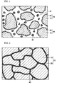
- FIG. 1 is a diagram that schematically shows the soft magnetic material according to the first embodiment of the present invention.
- the soft magnetic material in the present embodiment comprises a plurality of composite magnetic particles 30 having metallic magnetic particles 10 that are composed of pure iron, and an insulation film 20 that surrounds the surface of the metallic magnetic particles 10.
- the soft magnetic material may also include a resin 40, a lubricant (not shown), and other components in addition to the composite magnetic particles 30.
- FIG. 2 is an enlarged cross-sectional view of the powder magnetic core according to the first embodiment of the present invention.
- the powder magnetic core in FIG. 2 is manufactured by press-molding and heat-treating the soft magnetic material in FIG. 1 .
- the composite magnetic particles 30 in the powder magnetic core in the present embodiment are bonded together by an insulation film 40, or bonded together by causing the concavities and convexities of the composite magnetic particles 30 to mesh together.
- the insulation film 40 is one in which the resin 40 or the like contained in the soft magnetic material is changed during heat treatment.
- the Mn content of the metallic magnetic particles 10 is 0.013 mass% or less, and is preferably 0.008 mass% or less.
- the Mn content can be measured by inductively coupled plasma/atomic emission spectroscopy (ICP-AES).
- ICP-AES inductively coupled plasma/atomic emission spectroscopy
- the insulation film and resin are removed by a suitable pulverization (in the case of a powder magnetic core) and chemical treatment to perform the measurement.
- the mean grain size of the metallic magnetic particles 10 is preferably 30 ⁇ m or more and 500 ⁇ m or less.
- the coercive force can be reduced by setting the mean grain size of metallic magnetic particles 10 to be 30 ⁇ m or more.
- Eddy current loss can be reduced by setting the mean grain size to be 500 ⁇ m or less.
- a reduction in the compressibility of the mixed powder during pressure molding can also be reduced.
- a reduction in the density of the molded article obtained by pressure molding is thereby deterred, thus avoiding a situation in which the article is made more difficult to handle.
- the mean grain size of the metallic magnetic particles 10 refers to a grain size in which the sum of the masses from the smallest grain sizes has reached 50% of the total mass, i.e., 50% grain size in a histogram of the grain sizes.
- the insulation film 20 functions as an insulation layer between the metallic magnetic particles 10.
- the electrical resistivity p of the powder magnetic core obtained by press-molding the soft magnetic material can be increased by using the insulation film 20 to coat the metallic magnetic particles 10. Eddy current can thereby be prevented from flowing between the metallic magnetic particles 10, and the eddy current loss of the powder magnetic core can be reduced.
- the mean thickness of the insulation film 20 is preferably 10 nm or more and 1 ⁇ m or less. Energy loss due to eddy current can be effectively reduced by setting the mean thickness of the insulation film 20 to be 10 nm or more.
- the insulation film 20 can be prevented from shear-fracturing during pressure molding by setting the mean thickness of the insulation film to be 1 ⁇ m or less. Since the ratio of insulation film 20 to the soft magnetic material is not excessive, it is possible to prevent a marked reduction in the magnetic flux density of the powder magnetic core obtained by press-molding the soft magnetic material.
- the insulation film 20 comprises iron phosphate, aluminum phosphate, silicon phosphate, magnesium phosphate, calcium phosphate, yttrium phosphate, zirconium phosphate, or a silicon-based organic compound.
- Examples of the resin 40 include polyethylene resin, silicone resin, polyamide resin, polyimide resin, polyamide-imide resin, epoxy resin, phenol resin, acrylic resin, and fluororesin.
- FIG. 3 is a diagram showing, as a sequence of steps, the method for manufacturing a powder magnetic core according to the first embodiment of the present invention.
- metallic magnetic particles are treated so that the Mn content of the metallic magnetic particles is brought to 0.013 mass% or less, or more preferably 0.008 mass% or less (step S1).
- highly pure electrolytic iron in which the Mn content is 0.013 mass% or less is prepared, and the highly pure electrolytic iron is pulverized by atomization to obtain metallic magnetic particles 10.
- the Mn content of the metallic magnetic particles may be reduced and set at a level of 0.013 mass% or less by heating metallic magnetic particles having an Mn content greater than 0.013 mass% in an Mn reducing atmosphere.
- the reductive reactions expressed by formulas (1) and (2) below are typically brought about and Mn is removed from the metallic magnetic particles as MnS and MnCl 2 when, for example, a suitable amount of FeS powder and FeCl 3 powder is adsorbed onto the surface of the metallic magnetic particles having an Mn content greater than 0.013 mass%, and the particles are heat-treated (pre-annealed) in a reducing atmosphere (e.g., hydrogen atmosphere) at a temperature that is 1,000°C or higher and 50°C less than the melting point of iron.
- the heat treatment temperature is preferably a temperature that is lower than the temperature at which the metallic magnetic particles sinter together and cannot disintegrate.
- the element combined with a Fe compound and used for reducing Mn may be an element other than S and Cl, as long as the element for which the free energy of producing a compound with Mn is less than the free energy of producing a compound with Fe.
- the metallic magnetic particles 10 are heat-treated at a temperature of 400°C or higher and less than 900°C, for example (step S2).
- the heat treatment temperature is even more preferably 700°C or higher and less than 900°C.
- Strain, and numerous other defects present at the crystal grain boundaries inside the metallic magnetic particles 10 prior to heat treatment are due to heat stress produced during atomizing treatment and to stress produced by disintegration after the above-described Mn reducing treatment. In view of this situation, these defects can be reduced by heat-treating the metallic magnetic particles 10.
- the Mn content of the metallic magnetic particles 10 is 0.013 mass% or less, Mn compounds do not obstruct the growth of Fe crystal grains, and defects present in the metallic magnetic particles 10 can be adequately removed by heat treatment. This heat treatment may be omitted.
- an insulation film 20 is formed on the surface of each of the metallic magnetic particles 10 (step S3).
- a plurality of composite magnetic particles 30 is obtained by this step.
- the insulation film 20 can be formed by subjecting the metallic magnetic particles 10 to phosphate conversion treatment, for example.
- Examples of an insulation film 20 formed by phosphate conversion treatment include iron phosphates composed of phosphorus and iron, as well as aluminum phosphate, silicon phosphate, magnesium phosphate, calcium phosphate, yttrium phosphate, and zirconium phosphate. Solvent blowing or sol-gel treatment using a precursor can be used to form these phosphate insulation films.
- an insulation film 20 composed of a silicon-based organic compound may be formed. Wet coating treatment using an organic solvent, direct-coating treatment using a mixer, and other coating treatments may also be used.
- An oxide-containing insulation film 20 may also be formed.
- oxide insulators that can be used as the oxide-containing insulation film 20 include silicon oxide, titanium oxide, aluminum oxide, and zirconium oxide. Solvent blowing or sol-gel treatment using a precursor can be used to form these insulation films.
- step S4 resin 40 is mixed with the composite magnetic particles 30 (step S4).
- the method of mixing the components is not particularly limited, and examples of mixing methods include mechanical alloying; mixing by using a vibration ball mill or planetary ball mill; and using methods such as mechanofusion, co-precipitation, chemical vapor deposition (CVD), physical vapor deposition (PVD), plating, sputtering, vapor deposition, or the sol-gel method.
- a lubricant may also be mixed with the particles.
- the mixing step may be omitted.
- the soft magnetic material of the present embodiment shown in FIG. 1 can be obtained by the above-described steps. The following steps are further carried out when the powder magnetic core shown in FIG. 2 is manufactured.
- the resulting soft magnetic material powder is subsequently placed in a mold and pressure-molded using pressure in a range of, e.g., 390 (MPa) to 1,500 (MPa) (step S5).
- a molded article in which the soft magnetic material is compacted can thereby be obtained.
- the atmosphere for pressure molding is preferably an inert gas atmosphere or a reduced-pressure atmosphere. In this case, mixed powder can be prevented from being oxidized by oxygen in the atmosphere.
- the molded article obtained by pressure molding is heat-treated at a temperature that is, e.g., equal to or greater than 575°C but is less than the thermal decomposition temperature of the insulation film 20 (step S6). Since a large number of defects are generated inside the molded article produced by pressure molding, these defects can be removed by heat treatment.
- the Mn content of the metallic magnetic particles 10 is 0.013 mass% or less. Therefore, Mn compounds do not obstruct the growth of Fe crystal grains, and defects present in the metallic magnetic particles 10 can be adequately removed by heat treatment. In particular, the recrystallization of Fe can be promoted and grain boundaries can be reduced by conducting a heat treatment at a temperature of 575°C or higher.
- a powder magnetic core can be obtained in which the coercive force in a maximum applied magnetic field of 8,000 A/m is 120 A/m or less, and the iron loss at a maximum magnetic flux density of 1.0 T and a frequency of 1,000 Hz is 75 W/kg or less.
- the growth of Fe crystal grains can be promoted and defects in the metallic magnetic particles 10 can be adequately removed with the aid of a heat treatment by setting the Mn content of the metallic magnetic particles 10 to be 0.013 mass% or less. As a result, hysteresis loss can be effectively reduced.
- powder magnetic cores of the present invention examples A to C and the comparative examples D to F of the present invention were manufactured using the following method.
- Present Invention Example B Pure iron having an Mn content of 0.005 mass% was pulverized by gas atomization to prepare metallic magnetic particles. A powder magnetic core was thereafter obtained using the same manufacturing method as in the present invention example A.
- Present Invention Example C Pure iron having an Mn content of 0.01 mass% was pulverized by gas atomization to prepare metallic magnetic particles. A powder magnetic core was thereafter obtained using the same manufacturing method as in the present invention example A.
- Comparative Example D Pure iron having an Mn content of 0.02 mass% was pulverized by gas atomization to prepare metallic magnetic particles. A powder magnetic core was thereafter obtained using the same manufacturing method as in the present invention example A.
- Comparative Example E Pure iron having an Mn content of 0.05 mass% was pulverized by gas atomization to prepare metallic magnetic particles. A powder magnetic core was thereafter obtained using the same manufacturing method as in the present invention example A.
- Comparative Example F Pure iron having an Mn content of 0.10 mass% was pulverized by gas atomization to prepare metallic magnetic particles. A powder magnetic core was thereafter obtained using the same manufacturing method as in the present invention example A.
- the powder magnetic cores thus obtained were wound on a ringed molded article (heat-treated) having an outside diameter of 34 mm, an inside diameter of 20 mm, and a thickness of 5 mm so that the primary winding had 300 turns and the secondary winding had 20 turns, yielding samples for measuring the magnetic characteristics.
- the coercive force of these samples was measured in a maximum applied magnetic field of 8,000 A/m by using an alternating-current BH curve tracer.
- Hysteresis loss and iron loss were also measured using the alternating-current BH curve tracer.
- Hysteresis loss was calculated from the iron loss. This calculation was carried out by fitting the frequency curve of the iron loss in accordance with the least-squares method with the aid of the following three formulas, and the hysteresis loss coefficient and eddy current loss coefficient were calculated.
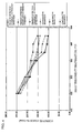
- the coercive force Hc of the present invention examples A to C was markedly reduced, as shown in TABLE 1 and FIG. 4 .
- the coercive force Hc was 1.41 ⁇ 10 2 A/m or higher in the comparative examples D to F, and 1.34 ⁇ 10 2 to 1.03 ⁇ 10 2 A/m in the present invention examples A to C.
- the coercive force Hc in the present invention examples A and B was 1.21 ⁇ 10 2 or less, showing particularly marked reduction.
- the hysteresis loss Wh 10/1000 of the present invention examples A to C was markedly reduced in conjunction with the reduction in coercive force Hc.
- the hysteresis loss was 46 to 58 W/kg or higher in the present invention examples A to C, but was 60 W/kg or higher in the comparative examples D to F.
- the coercive force Hc was 120 A/m or less, and the iron loss was 75 W/kg or less.
- the soft magnetic material, powder magnetic core, method for manufacturing soft magnetic material, and method for manufacturing a powder magnetic core according to the present invention may be used, e.g., in motor cores, solenoid valves, reactors, and general electromagnetic components.
Landscapes
- Engineering & Computer Science (AREA)
- Chemical & Material Sciences (AREA)
- Power Engineering (AREA)
- General Chemical & Material Sciences (AREA)
- Materials Engineering (AREA)
- Mechanical Engineering (AREA)
- Metallurgy (AREA)
- Organic Chemistry (AREA)
- Manufacturing & Machinery (AREA)
- Chemical Kinetics & Catalysis (AREA)
- Dispersion Chemistry (AREA)
- Powder Metallurgy (AREA)
- Soft Magnetic Materials (AREA)
Applications Claiming Priority (2)
| Application Number | Priority Date | Filing Date | Title |
|---|---|---|---|
| JP2005243888A JP4710485B2 (ja) | 2005-08-25 | 2005-08-25 | 軟磁性材料の製造方法、および圧粉磁心の製造方法 |
| PCT/JP2006/314262 WO2007023627A1 (fr) | 2005-08-25 | 2006-07-19 | Matériau magnétique mou, noyau à poudre de fer, procédé de production d’un matériau magnétique mou, et procédé de production d’un noyau à poudre de fer |
Publications (3)
| Publication Number | Publication Date |
|---|---|
| EP1918943A1 true EP1918943A1 (fr) | 2008-05-07 |
| EP1918943A4 EP1918943A4 (fr) | 2010-11-10 |
| EP1918943B1 EP1918943B1 (fr) | 2012-09-05 |
Family
ID=37771378
Family Applications (1)
| Application Number | Title | Priority Date | Filing Date |
|---|---|---|---|
| EP06768288A Not-in-force EP1918943B1 (fr) | 2005-08-25 | 2006-07-19 | Procédé de production d'un matériau magnétique doux, et procédé de production d'un noyau de poudre |
Country Status (5)
| Country | Link |
|---|---|
| US (1) | US7556838B2 (fr) |
| EP (1) | EP1918943B1 (fr) |
| JP (1) | JP4710485B2 (fr) |
| CN (1) | CN101053047A (fr) |
| WO (1) | WO2007023627A1 (fr) |
Cited By (1)
| Publication number | Priority date | Publication date | Assignee | Title |
|---|---|---|---|---|
| EP2472530A1 (fr) * | 2010-12-28 | 2012-07-04 | Kabushiki Kaisha Kobe Seiko Sho (Kobe Steel, Ltd.) | Poudre magnétique douce à base de fer pour noyau à poudre de fer, son procédé de préparation et noyau à poudre de fer |
Families Citing this family (13)
| Publication number | Priority date | Publication date | Assignee | Title |
|---|---|---|---|---|
| JP4707054B2 (ja) * | 2005-08-03 | 2011-06-22 | 住友電気工業株式会社 | 軟磁性材料、軟磁性材料の製造方法、圧粉磁心および圧粉磁心の製造方法 |
| JP4706411B2 (ja) * | 2005-09-21 | 2011-06-22 | 住友電気工業株式会社 | 軟磁性材料、圧粉磁心、軟磁性材料の製造方法、および圧粉磁心の製造方法 |
| JP5227756B2 (ja) * | 2008-01-31 | 2013-07-03 | 本田技研工業株式会社 | 軟磁性材料の製造方法 |
| JP4513131B2 (ja) | 2008-05-23 | 2010-07-28 | 住友電気工業株式会社 | 軟磁性材料の製造方法、および圧粉磁心の製造方法 |
| CN102046310B (zh) * | 2008-11-26 | 2013-09-25 | 住友电气工业株式会社 | 制造软磁性材料的方法以及制造压粉铁心的方法 |
| JPWO2010084812A1 (ja) * | 2009-01-22 | 2012-07-19 | 住友電気工業株式会社 | 冶金用粉末の製造方法、圧粉磁心の製造方法、圧粉磁心およびコイル部品 |
| EP2492031B1 (fr) | 2009-12-25 | 2017-10-18 | Tamura Corporation | Noyau de poudre et son procédé de production |
| CN102136329A (zh) * | 2011-04-01 | 2011-07-27 | 钢铁研究总院 | 一种铁基复合软磁材料及其制备方法 |
| JP5892421B2 (ja) * | 2012-02-16 | 2016-03-23 | 日立金属株式会社 | 金属粉末、その製造方法、及び圧粉磁心 |
| US10074468B2 (en) | 2013-03-27 | 2018-09-11 | Hitachi Chemical Company, Ltd. | Powder magnetic core for reactor |
| CA2859414C (fr) * | 2014-04-04 | 2017-03-14 | Matsuura Machinery Corporation | Equipement de traitement de poudre metallique |
| JP6926419B2 (ja) * | 2016-09-02 | 2021-08-25 | Tdk株式会社 | 圧粉磁心 |
| CN108346508B (zh) * | 2017-01-23 | 2021-07-06 | 中国科学院宁波材料技术与工程研究所 | 一种纳米晶复相钕铁硼永磁体织构化增强的制备方法 |
Family Cites Families (16)
| Publication number | Priority date | Publication date | Assignee | Title |
|---|---|---|---|---|
| JPS5848611A (ja) * | 1981-09-18 | 1983-03-22 | Mitsui Toatsu Chem Inc | 強磁性鉄粉体の製造方法 |
| JPH06940B2 (ja) * | 1985-05-29 | 1994-01-05 | 新日本製鐵株式会社 | 高マンガン鉄合金の溶融還元精錬方法 |
| US5252148A (en) * | 1989-05-27 | 1993-10-12 | Tdk Corporation | Soft magnetic alloy, method for making, magnetic core, magnetic shield and compressed powder core using the same |
| JP2564994B2 (ja) * | 1991-10-14 | 1996-12-18 | 日本鋼管株式会社 | 直流磁化特性と耐食性に優れた軟磁性鋼材およびその製造方法 |
| WO2002058085A1 (fr) * | 2001-01-19 | 2002-07-25 | Kabushiki Kaisha Toyota Chuo Kenkyusho | Noyau agglomere et procede de production dudit noyau |
| JP3986043B2 (ja) | 2001-02-20 | 2007-10-03 | 日立粉末冶金株式会社 | 圧粉磁心及びその製造方法 |
| JP3656958B2 (ja) * | 2001-04-27 | 2005-06-08 | 株式会社豊田中央研究所 | 圧粉磁心およびその製造方法 |
| JP2003243215A (ja) * | 2002-02-21 | 2003-08-29 | Matsushita Electric Ind Co Ltd | 複合磁性材料 |
| JP4060101B2 (ja) * | 2002-03-20 | 2008-03-12 | 株式会社豊田中央研究所 | 絶縁皮膜、磁心用粉末および圧粉磁心並びにそれらの製造方法 |
| JP2005015914A (ja) | 2003-06-03 | 2005-01-20 | Sumitomo Electric Ind Ltd | 複合磁性材料およびその製造方法 |
| JP2005142522A (ja) * | 2003-10-16 | 2005-06-02 | Sumitomo Electric Ind Ltd | 軟磁性材料の製造方法、軟磁性材料および圧粉磁心 |
| JP2005187918A (ja) * | 2003-12-26 | 2005-07-14 | Jfe Steel Kk | 圧粉磁心用絶縁被覆鉄粉 |
| JP4457682B2 (ja) * | 2004-01-30 | 2010-04-28 | 住友電気工業株式会社 | 圧粉磁心およびその製造方法 |
| JP2005213621A (ja) * | 2004-01-30 | 2005-08-11 | Sumitomo Electric Ind Ltd | 軟磁性材料および圧粉磁心 |
| JP4707054B2 (ja) * | 2005-08-03 | 2011-06-22 | 住友電気工業株式会社 | 軟磁性材料、軟磁性材料の製造方法、圧粉磁心および圧粉磁心の製造方法 |
| JP4706411B2 (ja) * | 2005-09-21 | 2011-06-22 | 住友電気工業株式会社 | 軟磁性材料、圧粉磁心、軟磁性材料の製造方法、および圧粉磁心の製造方法 |
-
2005
- 2005-08-25 JP JP2005243888A patent/JP4710485B2/ja not_active Expired - Fee Related
-
2006
- 2006-07-19 EP EP06768288A patent/EP1918943B1/fr not_active Not-in-force
- 2006-07-19 US US11/662,886 patent/US7556838B2/en not_active Expired - Fee Related
- 2006-07-19 WO PCT/JP2006/314262 patent/WO2007023627A1/fr not_active Ceased
- 2006-07-19 CN CNA2006800011118A patent/CN101053047A/zh active Pending
Cited By (2)
| Publication number | Priority date | Publication date | Assignee | Title |
|---|---|---|---|---|
| EP2472530A1 (fr) * | 2010-12-28 | 2012-07-04 | Kabushiki Kaisha Kobe Seiko Sho (Kobe Steel, Ltd.) | Poudre magnétique douce à base de fer pour noyau à poudre de fer, son procédé de préparation et noyau à poudre de fer |
| US9275779B2 (en) | 2010-12-28 | 2016-03-01 | Kobe Steel, Ltd. | Iron-based soft magnetic powder for dust core, preparation process thereof, and dust core |
Also Published As
| Publication number | Publication date |
|---|---|
| CN101053047A (zh) | 2007-10-10 |
| EP1918943A4 (fr) | 2010-11-10 |
| US20070264521A1 (en) | 2007-11-15 |
| EP1918943B1 (fr) | 2012-09-05 |
| JP2007059656A (ja) | 2007-03-08 |
| WO2007023627A1 (fr) | 2007-03-01 |
| US7556838B2 (en) | 2009-07-07 |
| JP4710485B2 (ja) | 2011-06-29 |
Similar Documents
| Publication | Publication Date | Title |
|---|---|---|
| EP2154694B1 (fr) | Matériau magnétique doux, noyau magnétique de poudre, processus de production de matériau magnétique doux, et processus de production de noyau magnétique de poudre | |
| US8481178B2 (en) | Iron powder coated with Mg-containing oxide film | |
| EP2947670A1 (fr) | Procédé de fabrication de noyau magnétique en poudre, noyau magnétique en poudre et composant de bobine | |
| EP1912225A1 (fr) | Matériau magnétique souple, procédé de fabrication du matériau, noyau magnétique comprimé en poudre, et procédé de fabrication du noyau magnétique | |
| EP1918943B1 (fr) | Procédé de production d'un matériau magnétique doux, et procédé de production d'un noyau de poudre | |
| WO2013108643A1 (fr) | Corps de poudre magnétique doux comprimé | |
| EP1716946A1 (fr) | Materiau magnetique mou et noyau a poudre de fer | |
| CN101142044B (zh) | 含Mg氧化膜包覆的铁粉末 | |
| CN1938114B (zh) | 软磁性材料的制造方法、软磁性粉末和压粉磁芯 | |
| JP7016713B2 (ja) | 圧粉磁心および磁心用粉末 | |
| EP1675136B1 (fr) | Materiau a aimantation temporaire et noyau magnetique pulverulent | |
| US11699542B2 (en) | Dust core | |
| EP3511960B1 (fr) | Noyau magnétique de poudre comprimée et poudre de noyau magnétique, et procédé de fabrication associé | |
| EP1675137A1 (fr) | Procede de production de matiere magnetique douce, matiere magnetique douce et noyau magnetique en poudre | |
| JP2008297622A (ja) | 軟磁性材料、圧粉磁心、軟磁性材料の製造方法および圧粉磁心の製造方法 | |
| US20150017056A1 (en) | Soft magnetic metal powder, method for preparing the same, and electronic components including the same as core material | |
| JP2007070719A (ja) | 堆積酸化膜被覆Fe−Si系鉄基軟磁性粉末およびその製造方法 | |
| EP1662517A1 (fr) | Materiau a aimantation temporaire et procede de fabrication | |
| JP2005213619A (ja) | 軟磁性材料およびその製造方法 | |
| WO2007052772A1 (fr) | POUDRE MAGNETIQUE TENDRE DE TYPE Fe-Si A BASE DE FER ENDUITE D'UN FILM DE DEPOT D'OXYDE ET SON PROCEDE DE PRODUCTION | |
| JP2005303007A (ja) | 軟磁性材料、圧粉磁心、および軟磁性材料の製造方法 | |
| JP2006324612A (ja) | 堆積酸化膜被覆鉄シリコン粉末およびその粉末の圧粉焼成体からなる複合軟磁性材 | |
| JP2007129093A (ja) | 軟磁性材料およびこれを用いて製造された圧粉磁心 | |
| JP2005142547A (ja) | 軟磁性材料および圧粉磁心 | |
| JP2008041685A (ja) | 圧粉磁心 |
Legal Events
| Date | Code | Title | Description |
|---|---|---|---|
| PUAI | Public reference made under article 153(3) epc to a published international application that has entered the european phase |
Free format text: ORIGINAL CODE: 0009012 |
|
| 17P | Request for examination filed |
Effective date: 20070328 |
|
| AK | Designated contracting states |
Kind code of ref document: A1 Designated state(s): DE FR IT |
|
| RBV | Designated contracting states (corrected) |
Designated state(s): DE FR IT |
|
| A4 | Supplementary search report drawn up and despatched |
Effective date: 20101007 |
|
| RIC1 | Information provided on ipc code assigned before grant |
Ipc: H01F 41/02 20060101ALI20111130BHEP Ipc: H01F 1/24 20060101AFI20111130BHEP Ipc: B22F 1/02 20060101ALI20111130BHEP |
|
| RTI1 | Title (correction) |
Free format text: METHOD FOR MANUFACTURING SOFT MAGNETIC MATERIAL, AND METHOD FOR MANUFACTURING POWDER MAGNETIC CORE |
|
| GRAP | Despatch of communication of intention to grant a patent |
Free format text: ORIGINAL CODE: EPIDOSNIGR1 |
|
| GRAS | Grant fee paid |
Free format text: ORIGINAL CODE: EPIDOSNIGR3 |
|
| DAX | Request for extension of the european patent (deleted) | ||
| GRAA | (expected) grant |
Free format text: ORIGINAL CODE: 0009210 |
|
| AK | Designated contracting states |
Kind code of ref document: B1 Designated state(s): DE FR IT |
|
| REG | Reference to a national code |
Ref country code: DE Ref legal event code: R096 Ref document number: 602006031841 Country of ref document: DE Effective date: 20121025 |
|
| PLBE | No opposition filed within time limit |
Free format text: ORIGINAL CODE: 0009261 |
|
| STAA | Information on the status of an ep patent application or granted ep patent |
Free format text: STATUS: NO OPPOSITION FILED WITHIN TIME LIMIT |
|
| 26N | No opposition filed |
Effective date: 20130606 |
|
| REG | Reference to a national code |
Ref country code: DE Ref legal event code: R097 Ref document number: 602006031841 Country of ref document: DE Effective date: 20130606 |
|
| REG | Reference to a national code |
Ref country code: FR Ref legal event code: PLFP Year of fee payment: 10 |
|
| PGFP | Annual fee paid to national office [announced via postgrant information from national office to epo] |
Ref country code: FR Payment date: 20150629 Year of fee payment: 10 |
|
| PGFP | Annual fee paid to national office [announced via postgrant information from national office to epo] |
Ref country code: IT Payment date: 20150727 Year of fee payment: 10 |
|
| PG25 | Lapsed in a contracting state [announced via postgrant information from national office to epo] |
Ref country code: FR Free format text: LAPSE BECAUSE OF NON-PAYMENT OF DUE FEES Effective date: 20160801 |
|
| REG | Reference to a national code |
Ref country code: FR Ref legal event code: ST Effective date: 20170331 |
|
| PG25 | Lapsed in a contracting state [announced via postgrant information from national office to epo] |
Ref country code: IT Free format text: LAPSE BECAUSE OF NON-PAYMENT OF DUE FEES Effective date: 20160719 |
|
| PGFP | Annual fee paid to national office [announced via postgrant information from national office to epo] |
Ref country code: DE Payment date: 20170711 Year of fee payment: 12 |
|
| REG | Reference to a national code |
Ref country code: DE Ref legal event code: R119 Ref document number: 602006031841 Country of ref document: DE |
|
| PG25 | Lapsed in a contracting state [announced via postgrant information from national office to epo] |
Ref country code: DE Free format text: LAPSE BECAUSE OF NON-PAYMENT OF DUE FEES Effective date: 20190201 |