EP1923638B1 - Dispositif de cuisson - Google Patents
Dispositif de cuisson Download PDFInfo
- Publication number
- EP1923638B1 EP1923638B1 EP06783037A EP06783037A EP1923638B1 EP 1923638 B1 EP1923638 B1 EP 1923638B1 EP 06783037 A EP06783037 A EP 06783037A EP 06783037 A EP06783037 A EP 06783037A EP 1923638 B1 EP1923638 B1 EP 1923638B1
- Authority
- EP
- European Patent Office
- Prior art keywords
- door
- gasket
- section
- comb teeth
- microwave
- Prior art date
- Legal status (The legal status is an assumption and is not a legal conclusion. Google has not performed a legal analysis and makes no representation as to the accuracy of the status listed.)
- Not-in-force
Links
- 238000010411 cooking Methods 0.000 title claims abstract description 22
- 238000010438 heat treatment Methods 0.000 claims abstract description 25
- 239000002184 metal Substances 0.000 abstract description 11
- 238000005452 bending Methods 0.000 description 18
- 238000007789 sealing Methods 0.000 description 12
- 230000000712 assembly Effects 0.000 description 5
- 238000000429 assembly Methods 0.000 description 5
- 230000001771 impaired effect Effects 0.000 description 3
- 230000002411 adverse Effects 0.000 description 2
- 238000004519 manufacturing process Methods 0.000 description 2
- 238000000034 method Methods 0.000 description 2
- 244000126211 Hericium coralloides Species 0.000 description 1
- 240000007594 Oryza sativa Species 0.000 description 1
- 235000007164 Oryza sativa Nutrition 0.000 description 1
- 229910000831 Steel Inorganic materials 0.000 description 1
- 239000002131 composite material Substances 0.000 description 1
- 229920001971 elastomer Polymers 0.000 description 1
- 239000000806 elastomer Substances 0.000 description 1
- 230000008020 evaporation Effects 0.000 description 1
- 238000001704 evaporation Methods 0.000 description 1
- 238000001125 extrusion Methods 0.000 description 1
- 235000013305 food Nutrition 0.000 description 1
- 239000011521 glass Substances 0.000 description 1
- 238000009434 installation Methods 0.000 description 1
- 239000000463 material Substances 0.000 description 1
- 238000012986 modification Methods 0.000 description 1
- 230000004048 modification Effects 0.000 description 1
- 230000002093 peripheral effect Effects 0.000 description 1
- 238000003825 pressing Methods 0.000 description 1
- 229920005989 resin Polymers 0.000 description 1
- 239000011347 resin Substances 0.000 description 1
- 235000009566 rice Nutrition 0.000 description 1
- 150000003839 salts Chemical class 0.000 description 1
- 229920002379 silicone rubber Polymers 0.000 description 1
- 239000004945 silicone rubber Substances 0.000 description 1
- 239000010959 steel Substances 0.000 description 1
- 229920003002 synthetic resin Polymers 0.000 description 1
- 239000000057 synthetic resin Substances 0.000 description 1
Images



Classifications
-
- H—ELECTRICITY
- H05—ELECTRIC TECHNIQUES NOT OTHERWISE PROVIDED FOR
- H05B—ELECTRIC HEATING; ELECTRIC LIGHT SOURCES NOT OTHERWISE PROVIDED FOR; CIRCUIT ARRANGEMENTS FOR ELECTRIC LIGHT SOURCES, IN GENERAL
- H05B6/00—Heating by electric, magnetic or electromagnetic fields
- H05B6/64—Heating using microwaves
- H05B6/76—Prevention of microwave leakage, e.g. door sealings
- H05B6/763—Microwave radiation seals for doors
-
- A—HUMAN NECESSITIES
- A21—BAKING; EDIBLE DOUGHS
- A21B—BAKERS' OVENS; MACHINES OR EQUIPMENT FOR BAKING
- A21B3/00—Parts or accessories of ovens
- A21B3/04—Air-treatment devices for ovens, e.g. regulating humidity
-
- F—MECHANICAL ENGINEERING; LIGHTING; HEATING; WEAPONS; BLASTING
- F24—HEATING; RANGES; VENTILATING
- F24C—DOMESTIC STOVES OR RANGES ; DETAILS OF DOMESTIC STOVES OR RANGES, OF GENERAL APPLICATION
- F24C15/00—Details
- F24C15/02—Doors specially adapted for stoves or ranges
- F24C15/021—Doors specially adapted for stoves or ranges sealings for doors or transparent panel
-
- F—MECHANICAL ENGINEERING; LIGHTING; HEATING; WEAPONS; BLASTING
- F24—HEATING; RANGES; VENTILATING
- F24C—DOMESTIC STOVES OR RANGES ; DETAILS OF DOMESTIC STOVES OR RANGES, OF GENERAL APPLICATION
- F24C15/00—Details
- F24C15/32—Arrangements of ducts for hot gases, e.g. in or around baking ovens
- F24C15/322—Arrangements of ducts for hot gases, e.g. in or around baking ovens with forced circulation
- F24C15/327—Arrangements of ducts for hot gases, e.g. in or around baking ovens with forced circulation with air moisturising
-
- H—ELECTRICITY
- H05—ELECTRIC TECHNIQUES NOT OTHERWISE PROVIDED FOR
- H05B—ELECTRIC HEATING; ELECTRIC LIGHT SOURCES NOT OTHERWISE PROVIDED FOR; CIRCUIT ARRANGEMENTS FOR ELECTRIC LIGHT SOURCES, IN GENERAL
- H05B6/00—Heating by electric, magnetic or electromagnetic fields
- H05B6/64—Heating using microwaves
- H05B6/6414—Aspects relating to the door of the microwave heating apparatus
-
- H—ELECTRICITY
- H05—ELECTRIC TECHNIQUES NOT OTHERWISE PROVIDED FOR
- H05B—ELECTRIC HEATING; ELECTRIC LIGHT SOURCES NOT OTHERWISE PROVIDED FOR; CIRCUIT ARRANGEMENTS FOR ELECTRIC LIGHT SOURCES, IN GENERAL
- H05B6/00—Heating by electric, magnetic or electromagnetic fields
- H05B6/64—Heating using microwaves
- H05B6/647—Aspects related to microwave heating combined with other heating techniques
- H05B6/6473—Aspects related to microwave heating combined with other heating techniques combined with convection heating
- H05B6/6479—Aspects related to microwave heating combined with other heating techniques combined with convection heating using steam
-
- Y—GENERAL TAGGING OF NEW TECHNOLOGICAL DEVELOPMENTS; GENERAL TAGGING OF CROSS-SECTIONAL TECHNOLOGIES SPANNING OVER SEVERAL SECTIONS OF THE IPC; TECHNICAL SUBJECTS COVERED BY FORMER USPC CROSS-REFERENCE ART COLLECTIONS [XRACs] AND DIGESTS
- Y10—TECHNICAL SUBJECTS COVERED BY FORMER USPC
- Y10T—TECHNICAL SUBJECTS COVERED BY FORMER US CLASSIFICATION
- Y10T29/00—Metal working
- Y10T29/49—Method of mechanical manufacture
- Y10T29/49002—Electrical device making
- Y10T29/49016—Antenna or wave energy "plumbing" making
Definitions
- the present invention relates to a cooking device for performing cooking using a microwave and steam.
- a measure commonly taken to prevent leakage of a microwave is to provide a choke structure as described in Patent Publications 1 to 4 (listed below).
- a choke structure is provided at the door of a heating chamber, leakage is prevented relatively effectively at the sides of the door, but it is not easy to prevent leakage at the corners of the door.
- the choke provided at the four corners of the door is designed to have a particular longitudinal width.
- a slit-choke structure is provided in an the device described in Patent Publication 2
- a slit-choke structure is provided in an area where an upper or a lower hinge overlaps the door body.
- the bending angle at which a bent section is bent is larger near a corner than at other locations.
- protruding surface sections located near the corners of the door are designed to protrude more than those in other locations.
- a gasket is commonly used as described in Patent Publications 5 and 6.
- Patent Publication 2 JP-A-2043-109745 (Pages 2 and 3, Figs. 1 to 10 )
- Patent Publication 3 JP-A-H8-124b74 (Pages 3 and 4, Figs. 1 to 4 )
- Patent Publication 4 JP-A-H7-94272 (Pages 3 and 4, Figs. 1 to 5 )
- Patent Publication 5 JP-A-2000-30856 (Pages 2 and 3, Figs. 1 to 4 )
- Patent Publication 6 JP-A-H2-178524 (Page 2, Figs. 1 to 5 )
- JP 58175732 discloses a composite heating cooker wherein a gasket of semicircular heat-resistant resilient body is arranged along the inner wall of the door, while its one side is fixed between the door inner wall and the sealing wall.
- US5095657 discloses a clipless door seal for oven doors or the like including a sealing element having a length greater than its width, a pair of resilient elongated flanges depending from the outer surface of the sealing element and running substantially the entire length of the sealing element, and at least two resilient retaining darts for securing the door seal to an oven door surface.
- DE19935836 discloses an oven with an elastomer (in particular, silicone rubber) sealing profile attached to the oven or its door wherein the sealing profile within the top section of the oven has a deeper sealing element than the sealing profile in the bottom section of the oven.
- elastomer in particular, silicone rubber
- DE10131009 discloses a method for attaching a rectangular seal around an oven door opening wherein the sealing element has corner slots over which tag retainers are engaged and at least one further slot between corner with a longitudinal slot having a wider portion to take a hooked tag after which the seal is slid along to engage the tag in a narrow section.
- JP2001355844 discloses a cooker which includes an evaporation vessel which is formed of a material of low dielectric constant, and placed removably at an outlet of a wave guide for guiding a microwave into the oven chamber.
- JP2000030856 discloses a high-frequency heating system wherein an opening is provided on the front face of the cooking chamber of this system, a door is openably fitted to the opening, and the peripheral edge of the back plate of the door is folded to integrally form a choke groove.
- JP60041912 discloses a rice cooker.
- An object of the present invention is to provide a cooking device where such necessity is fulfilled.
- a door of a heating chamber is provided with: a choke structure that prevents leakage of the microwave from the heating chamber; and a gasket that is fitted near the choke structure with a choke cover for covering the choke structure and prevents leakage of the steam from the heating chamber, and a lip section of the gasket is designed to have a bag-like cross section in which an opening is formed on a side thereof that faces an inside of the heating chamber, an end of the lip section in the bag-like cross section being bent toward the door.
- steam pressure inside the heating chamber acts so as to inflate the bag-like cross section of the gasket, and thus the sealing function of the gasket is improved with an increase in steam pressure.
- a bending angle of metal comb teeth constituting the choke structure may be larger than in a case where the gasket is not installed, leaving metal comb teeth located at corners of the door as an exception.
- the phase of a microwave shifts when a gasket is provided near a choke structure, and thus conventional choke structures normally cannot prevent leakage of a microwave.
- the function to prevent leakage of a microwave can be maintained effective by making the bending angle at which the comb teeth are bent larger than in the case where no gasket is installed.
- making the bending angle larger adversely affects the comb teeth located at the corners of the door; however, this can be coped with by making the bending angle of such comb teeth, as an exception, not larger.
- the exception of the bending angle may be limited to comb teeth located near metal hinge assemblies of the door among those located at the corners of the door.
- comb teeth located at the corners of the door it is those located near the metal hinge assemblies that are adversely affected, with respect to the function to prevent leakage of a microwave, by being bent at a larger angle. Therefore, only the bending angle of such comb teeth is made different from that of the other comb teeth, and this helps facilitate the fabrication process of the choke structure.
- the lip section of the gasket has a bag-like cross section in which an opening is formed on the side thereof that faces the inside of the heating chamber, the bag-like cross section is inflated with an increase in steam pressure inside the heating chamber, and this enhances the sealing function of the gasket. Furthermore, since the edge of the lip section of the gasket is bent toward the door, it is not the edge of the lip section but the portion thereof corresponding to the middle portion of the bag-like cross section; thus, airtightness is not impaired even if the edge of the lip section is deformed by heat.
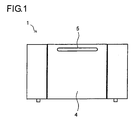
- a cooking device 1 includes a microwave generator and a steam generator (neither shown), and is capable of cooking by: using only a microwave, using only steam, and using a microwave and steam in combination.
- the cooking device 1 has a heating chamber 3 formed inside a cabinet 2 (see Fig. 2 ) and a door provided in the front center of the cabinet 2 so as to cover an opening of the heating chamber 3.
- the door 4 rotates in a vertical plane around a hinge section (not shown) provided at the bottom end thereof, and has a handle 5 provided at the front top thereof.
- the door 4 is composed of many components, among which the following three components should be noted: an inner frame 10, a choke cover 20, and a gasket 30.
- the inner frame 10 is formed by pressing a metal plate (more specifically, a steel plate) into a frame shape, and to a window 11 in the center of the inner frame 10, there are fitted a punched metal plate, a glass plate, etc. so as to prevent leakage of the microwave while permitting the inside of the heating chamber to be visible.
- a choke structure 12 is formed to prevent leakage of a microwave.
- the choke structure 12 is built by forming along the edge of a metal plate a large number of comb teeth 13 having a predetermined size and arranged at predetermined intervals, and bending these comb teeth 13 at a predetermined angle. The end of each of the comb teeth 13 faces the outer surface of an inner protruding wall 14 formed in the inner frame 10, with a predetermined distance between the ends and the outer surface.
- the choke cover 20 includes a wall 21 (see Fig. 3 ) that is formed to be in parallel with the comb teeth 13, and an inner edge section 22 that continues from the wall 21 faces the inner protruding wall 14 with a predetermined gap therebetween.
- a gasket 30 is a product of a highly heat-resistant flexible synthetic resin molded by extrusion molding, and is built by forming the following sections so as to be continuous to each other: a lip section 32 that is tightly pressed against a wall 6 around the opening of the heating chamber 3; and a base section 31 (see Fig. 3 ) that covers the inner edge section 22 of the choke cover 20.
- the lip section 32 has a bag-like cross section in which an opening is formed on the side thereof that faces the inside of the heating chamber 3. An edge of the lip section 32 is bent toward the door 4, and this makes the bag-like cross section thereof appear to be a bag with its mouth narrowed.
- the sealing function of the gasket 30 is improved with an increase in steam pressure.
- the edge of the lip section 32 is bent toward the door 4, and thus it is not the edge of the lip section 32 but the portion thereof corresponding to the middle portion of its bag-like cross section that is tightly pressed against the wall 6 and mainly serves to cut off gas flow. Therefore, airtightness is not impaired even if the edge of the lip section 32 is deformed by heat to be, for example, wavy.
- the phase of the microwave headed for the choke structure 12 is shifted.
- the angle at which the comb teeth 13 are bent is left as it is in the case where the gasket 30 is not provided, leakage of the microwave cannot be prevented.
- the bending angle at which the comb teeth 13 are bent is adjusted such that the function to prevent leakage of a microwave is maintained effective.
- Fig. 6 shows the comb teeth 13 bent at a larger bending angle, and the comb teeth 13 form an angle of approximately 45° with respect to the front surface of the inner frame 10. This enables the comb teeth 13 to restore its function to prevent leakage of the microwave.
- bending the comb teeth 13 at a larger angle is not effective to all the comb teeth 13.
- the comb teeth located at the corners of the door 4 that is, the pairs of comb teeth denoted by reference numeral 13a in Fig. 4
- the shortest distance between the ends of each pair of the comb teeth 13a becomes longer, and this deprives the comb teeth 13a of the function to prevent leakage of a microwave.
- the comb teeth 13a arranged next to each other are bent not at a bending angle larger than conventional but at a conventional bending angle.
- Fig. 7 shows such a comb tooth 13a.
- the comb teeth 13a form an angle of approximately 30° with respect to the front surface of the inner frame 10.
- the present invention is widely applicable to cooking devices for performing cooking using a microwave and steam in combination.
Landscapes
- Engineering & Computer Science (AREA)
- Physics & Mathematics (AREA)
- Electromagnetism (AREA)
- Chemical & Material Sciences (AREA)
- Combustion & Propulsion (AREA)
- Mechanical Engineering (AREA)
- General Engineering & Computer Science (AREA)
- Life Sciences & Earth Sciences (AREA)
- Food Science & Technology (AREA)
- Electric Ovens (AREA)
- Constitution Of High-Frequency Heating (AREA)
Abstract
Claims (2)
- Dispositif de cuisson (1) utilisant une combinaison de micro-ondes et de vapeur,
étant précisé qu'une porte (4) d'une chambre de chauffe (3) est pourvue :d'une structure d'étranglement (12) qui empêche une fuite des micro-ondes hors de la chambre de chauffe (3), etd'un joint (30) qui est installé près de la structure d'étranglement (12), avec un recouvrement d'étranglement (20) pour couvrir celle-ci, et qui empêche une fuite de vapeur hors de la chambre de chauffe (3),caractérisé en ce qu'une section formant lèvre (32) du joint (30) est conçue pour avoir une section transversale en forme de sac dans laquelle une ouverture est formée dans un côté qui fait face à l'intérieur de la chambre de chauffe (3), une extrémité de la section formant lèvre (32) dans la coupe transversale en forme de sac étant pliée vers la porte (4). - Dispositif de cuisson de la revendication 1, étant précisé que la section formant lèvre (32) du joint (30) a une coupe transversale qui ressemble à un sac dont l'ouverture est rétrécie.
Applications Claiming Priority (2)
| Application Number | Priority Date | Filing Date | Title |
|---|---|---|---|
| JP2005260016A JP4127553B2 (ja) | 2005-09-08 | 2005-09-08 | 加熱調理器 |
| PCT/JP2006/316697 WO2007029521A1 (fr) | 2005-09-08 | 2006-08-25 | Dispositif de cuisson |
Publications (3)
| Publication Number | Publication Date |
|---|---|
| EP1923638A1 EP1923638A1 (fr) | 2008-05-21 |
| EP1923638A4 EP1923638A4 (fr) | 2011-03-16 |
| EP1923638B1 true EP1923638B1 (fr) | 2012-05-16 |
Family
ID=37835644
Family Applications (1)
| Application Number | Title | Priority Date | Filing Date |
|---|---|---|---|
| EP06783037A Not-in-force EP1923638B1 (fr) | 2005-09-08 | 2006-08-25 | Dispositif de cuisson |
Country Status (6)
| Country | Link |
|---|---|
| US (1) | US8288695B2 (fr) |
| EP (1) | EP1923638B1 (fr) |
| JP (1) | JP4127553B2 (fr) |
| KR (1) | KR100975459B1 (fr) |
| CN (1) | CN100565016C (fr) |
| WO (1) | WO2007029521A1 (fr) |
Families Citing this family (10)
| Publication number | Priority date | Publication date | Assignee | Title |
|---|---|---|---|---|
| JP5214512B2 (ja) * | 2009-03-24 | 2013-06-19 | シャープ株式会社 | 加熱調理器 |
| CN102317691B (zh) * | 2009-04-16 | 2015-06-17 | 夏普株式会社 | 液体容器和加热烹调器 |
| JP2011179792A (ja) * | 2010-03-03 | 2011-09-15 | Sanyo Electric Co Ltd | 加熱調理器 |
| DE102012112805A1 (de) * | 2012-12-20 | 2014-06-26 | Miele & Cie. Kg | Gargerät |
| JP6074660B2 (ja) * | 2013-05-31 | 2017-02-08 | パナソニックIpマネジメント株式会社 | 加熱調理器 |
| DE102014201426A1 (de) * | 2014-01-27 | 2015-07-30 | BSH Hausgeräte GmbH | Gargerät |
| KR101991956B1 (ko) * | 2017-04-12 | 2019-06-24 | 엘지전자 주식회사 | 조리기기 |
| CN113662416B (zh) * | 2020-05-13 | 2025-02-07 | 宁波方太厨具有限公司 | 一种烹饪设备的内胆蒸汽发生结构 |
| BE1030966B1 (de) | 2022-10-18 | 2024-05-21 | Miele & Cie | Gargerät, vorzugsweise mit Selbstreinigungsfunktion und bzw. oder mit Dampfunktion, besonders vorzugsweise Backofen-Dampfgarer-Kombigerät, vorzugsweise mit Selbstreinigungsfunktion |
| KR20240170258A (ko) * | 2023-05-26 | 2024-12-03 | 엘지전자 주식회사 | 조리기기 |
Family Cites Families (19)
| Publication number | Priority date | Publication date | Assignee | Title |
|---|---|---|---|---|
| US4102041A (en) * | 1977-03-28 | 1978-07-25 | Amana Refrigeration, Inc. | Method of making microwave oven seal structure |
| JPS58175732A (ja) | 1982-04-07 | 1983-10-15 | Matsushita Electric Ind Co Ltd | 複合加熱調理器 |
| JPS6041912A (ja) | 1983-08-18 | 1985-03-05 | 松下電器産業株式会社 | 炊飯器 |
| JP2839272B2 (ja) | 1988-12-29 | 1998-12-16 | 松下電器産業株式会社 | 高周波加熱装置 |
| US5095657A (en) * | 1990-10-26 | 1992-03-17 | Marsh Richard B | Door seal |
| JPH0794272A (ja) | 1993-09-24 | 1995-04-07 | Sanyo Electric Co Ltd | 高周波加熱装置用扉 |
| JPH08124674A (ja) | 1994-10-24 | 1996-05-17 | Sanyo Electric Co Ltd | 高周波加熱装置 |
| US5615859A (en) * | 1995-03-24 | 1997-04-01 | Haag, Iii; Earl C. | Sterilizable valve assembly |
| KR0148906B1 (ko) * | 1995-04-03 | 1998-12-15 | 구자홍 | 전자레인지의 전파누설방지용 도어구조 |
| KR0171337B1 (ko) * | 1995-09-18 | 1999-05-01 | 배순훈 | 전자렌지 도어의 전파 차폐구조 |
| JP2000030856A (ja) | 1998-07-15 | 2000-01-28 | Sanyo Electric Co Ltd | 高周波加熱装置 |
| DE19935836C2 (de) | 1999-07-29 | 2001-08-09 | Bsh Bosch Siemens Hausgeraete | Gargerät mit einem Dichtungsprofil und entsprechendes Dichtungsprofil |
| JP2001355844A (ja) | 2000-06-16 | 2001-12-26 | Matsushita Electric Ind Co Ltd | 加熱調理装置 |
| DE10131009C2 (de) | 2001-06-27 | 2003-07-03 | Bsh Bosch Siemens Hausgeraete | Haushaltsgerät, insbesondere Backofen |
| JP2003109745A (ja) | 2001-09-28 | 2003-04-11 | Matsushita Electric Ind Co Ltd | 高周波加熱装置 |
| JP2003243150A (ja) | 2002-02-15 | 2003-08-29 | Mitsubishi Electric Corp | 高周波加熱装置の扉のチョーク構造 |
| JP2004321290A (ja) | 2003-04-22 | 2004-11-18 | Toshiba Home Technology Corp | 食品加熱保温器 |
| FR2862853B1 (fr) | 2003-11-27 | 2006-09-15 | Seb Sa | Appareil de cuisson sous pression muni d'un dispositif de securite a la surpression, et joint d'etancheite pour un tel appareil |
| JP2007115710A (ja) | 2006-12-22 | 2007-05-10 | Sharp Corp | 加熱調理器 |
-
2005
- 2005-09-08 JP JP2005260016A patent/JP4127553B2/ja not_active Expired - Fee Related
-
2006
- 2006-08-25 EP EP06783037A patent/EP1923638B1/fr not_active Not-in-force
- 2006-08-25 WO PCT/JP2006/316697 patent/WO2007029521A1/fr not_active Ceased
- 2006-08-25 US US12/066,046 patent/US8288695B2/en not_active Expired - Fee Related
- 2006-08-25 KR KR1020087005589A patent/KR100975459B1/ko not_active Expired - Fee Related
- 2006-08-25 CN CNB2006800329309A patent/CN100565016C/zh not_active Expired - Fee Related
Also Published As
| Publication number | Publication date |
|---|---|
| CN101258362A (zh) | 2008-09-03 |
| JP4127553B2 (ja) | 2008-07-30 |
| US20090134150A1 (en) | 2009-05-28 |
| US8288695B2 (en) | 2012-10-16 |
| KR20080033519A (ko) | 2008-04-16 |
| KR100975459B1 (ko) | 2010-08-11 |
| EP1923638A1 (fr) | 2008-05-21 |
| EP1923638A4 (fr) | 2011-03-16 |
| JP2007071464A (ja) | 2007-03-22 |
| CN100565016C (zh) | 2009-12-02 |
| WO2007029521A1 (fr) | 2007-03-15 |
Similar Documents
| Publication | Publication Date | Title |
|---|---|---|
| CN107251647B (zh) | 具有微波加热功能的炉及用于该炉的炉门 | |
| EP1923638B1 (fr) | Dispositif de cuisson | |
| EP2031939B1 (fr) | Dispositif de support à ondes pour porte de four à micro-ondes | |
| CN104919895B (zh) | 用于微波器具的门 | |
| US20130228568A1 (en) | Multiple choke system for containing wide frequency band rf leakage | |
| AU2010252320B2 (en) | A microwave oven with at least one wave choke system | |
| US10080263B2 (en) | Cooking device | |
| US9016270B2 (en) | Window mounting for thermal expansion in an oven appliance | |
| EP3933271B1 (fr) | Appareil de cuisson | |
| US20170318630A1 (en) | Cooking household appliance | |
| EP2541151A1 (fr) | Dispositif de cuisson haute fréquence | |
| JP2007115710A (ja) | 加熱調理器 | |
| CN113685857A (zh) | 微波烹饪器具的门体组件及具有其的微波烹饪器具 | |
| KR100518417B1 (ko) | 전자레인지 도어의 전자파 차단구조 | |
| CN216650041U (zh) | 门体组件及熟化箱 | |
| KR890003955Y1 (ko) | 전파 누설방지용 전자레인지의 도어 | |
| CN101164372A (zh) | 具有陷波器防护板的微波炉 | |
| CN216429451U (zh) | 一种可视门体组件及蒸汽烤箱 | |
| CN118044335A (zh) | 用于微波烹饪器具的烹饪室门以及微波烹饪器具 | |
| JP2005071739A (ja) | 高周波加熱調理装置およびその製造方法 | |
| CN110934507A (zh) | 用于烤箱的密封件和具有其的烤箱 | |
| HK1165178A (en) | A microwave oven with at least one wave choke system | |
| JPH0588518B2 (fr) | ||
| KR19980077540A (ko) | 전자레인지의 마이크로웨이브 누설방지구조 |
Legal Events
| Date | Code | Title | Description |
|---|---|---|---|
| PUAI | Public reference made under article 153(3) epc to a published international application that has entered the european phase |
Free format text: ORIGINAL CODE: 0009012 |
|
| 17P | Request for examination filed |
Effective date: 20080328 |
|
| AK | Designated contracting states |
Kind code of ref document: A1 Designated state(s): DE FR GB |
|
| DAX | Request for extension of the european patent (deleted) | ||
| RBV | Designated contracting states (corrected) |
Designated state(s): DE FR GB |
|
| A4 | Supplementary search report drawn up and despatched |
Effective date: 20110215 |
|
| RIC1 | Information provided on ipc code assigned before grant |
Ipc: F24C 15/00 20060101ALI20110209BHEP Ipc: F24C 1/00 20060101ALI20110209BHEP Ipc: F24C 7/02 20060101ALI20110209BHEP Ipc: H05B 6/64 20060101ALI20110209BHEP Ipc: H05B 6/76 20060101AFI20110209BHEP |
|
| REG | Reference to a national code |
Ref country code: DE Ref legal event code: R079 Ref document number: 602006029540 Country of ref document: DE Free format text: PREVIOUS MAIN CLASS: F24C0007020000 Ipc: H05B0006760000 |
|
| GRAP | Despatch of communication of intention to grant a patent |
Free format text: ORIGINAL CODE: EPIDOSNIGR1 |
|
| RIC1 | Information provided on ipc code assigned before grant |
Ipc: F24C 15/02 20060101ALI20111012BHEP Ipc: F24C 7/02 20060101ALI20111012BHEP Ipc: H05B 6/76 20060101AFI20111012BHEP Ipc: H05B 6/64 20060101ALI20111012BHEP Ipc: F24C 15/00 20060101ALI20111012BHEP Ipc: F24C 1/00 20060101ALI20111012BHEP |
|
| GRAS | Grant fee paid |
Free format text: ORIGINAL CODE: EPIDOSNIGR3 |
|
| GRAA | (expected) grant |
Free format text: ORIGINAL CODE: 0009210 |
|
| AK | Designated contracting states |
Kind code of ref document: B1 Designated state(s): DE FR GB |
|
| REG | Reference to a national code |
Ref country code: GB Ref legal event code: FG4D |
|
| REG | Reference to a national code |
Ref country code: DE Ref legal event code: R096 Ref document number: 602006029540 Country of ref document: DE Effective date: 20120712 |
|
| PLBE | No opposition filed within time limit |
Free format text: ORIGINAL CODE: 0009261 |
|
| STAA | Information on the status of an ep patent application or granted ep patent |
Free format text: STATUS: NO OPPOSITION FILED WITHIN TIME LIMIT |
|
| 26N | No opposition filed |
Effective date: 20130219 |
|
| REG | Reference to a national code |
Ref country code: DE Ref legal event code: R097 Ref document number: 602006029540 Country of ref document: DE Effective date: 20130219 |
|
| REG | Reference to a national code |
Ref country code: FR Ref legal event code: PLFP Year of fee payment: 11 |
|
| REG | Reference to a national code |
Ref country code: FR Ref legal event code: PLFP Year of fee payment: 12 |
|
| REG | Reference to a national code |
Ref country code: FR Ref legal event code: PLFP Year of fee payment: 13 |
|
| PGFP | Annual fee paid to national office [announced via postgrant information from national office to epo] |
Ref country code: DE Payment date: 20190822 Year of fee payment: 14 Ref country code: FR Payment date: 20190822 Year of fee payment: 14 |
|
| PGFP | Annual fee paid to national office [announced via postgrant information from national office to epo] |
Ref country code: GB Payment date: 20190821 Year of fee payment: 14 |
|
| REG | Reference to a national code |
Ref country code: DE Ref legal event code: R119 Ref document number: 602006029540 Country of ref document: DE |
|
| GBPC | Gb: european patent ceased through non-payment of renewal fee |
Effective date: 20200825 |
|
| PG25 | Lapsed in a contracting state [announced via postgrant information from national office to epo] |
Ref country code: FR Free format text: LAPSE BECAUSE OF NON-PAYMENT OF DUE FEES Effective date: 20200831 Ref country code: DE Free format text: LAPSE BECAUSE OF NON-PAYMENT OF DUE FEES Effective date: 20210302 |
|
| PG25 | Lapsed in a contracting state [announced via postgrant information from national office to epo] |
Ref country code: GB Free format text: LAPSE BECAUSE OF NON-PAYMENT OF DUE FEES Effective date: 20200825 |