EP1925777A1 - Flügelzellenpumpe - Google Patents
Flügelzellenpumpe Download PDFInfo
- Publication number
- EP1925777A1 EP1925777A1 EP07022034A EP07022034A EP1925777A1 EP 1925777 A1 EP1925777 A1 EP 1925777A1 EP 07022034 A EP07022034 A EP 07022034A EP 07022034 A EP07022034 A EP 07022034A EP 1925777 A1 EP1925777 A1 EP 1925777A1
- Authority
- EP
- European Patent Office
- Prior art keywords
- rotor
- vanes
- leading end
- vane pump
- end portion
- Prior art date
- Legal status (The legal status is an assumption and is not a legal conclusion. Google has not performed a legal analysis and makes no representation as to the accuracy of the status listed.)
- Withdrawn
Links
- 230000002093 peripheral effect Effects 0.000 claims abstract description 42
- 239000012530 fluid Substances 0.000 claims abstract description 14
- 230000003247 decreasing effect Effects 0.000 claims description 2
- 230000008878 coupling Effects 0.000 description 2
- 238000010168 coupling process Methods 0.000 description 2
- 238000005859 coupling reaction Methods 0.000 description 2
- 230000003993 interaction Effects 0.000 description 1
- 230000004048 modification Effects 0.000 description 1
- 238000012986 modification Methods 0.000 description 1
- 238000012856 packing Methods 0.000 description 1
Images




Classifications
-
- F—MECHANICAL ENGINEERING; LIGHTING; HEATING; WEAPONS; BLASTING
- F04—POSITIVE - DISPLACEMENT MACHINES FOR LIQUIDS; PUMPS FOR LIQUIDS OR ELASTIC FLUIDS
- F04C—ROTARY-PISTON, OR OSCILLATING-PISTON, POSITIVE-DISPLACEMENT MACHINES FOR LIQUIDS; ROTARY-PISTON, OR OSCILLATING-PISTON, POSITIVE-DISPLACEMENT PUMPS
- F04C18/00—Rotary-piston pumps specially adapted for elastic fluids
-
- F—MECHANICAL ENGINEERING; LIGHTING; HEATING; WEAPONS; BLASTING
- F01—MACHINES OR ENGINES IN GENERAL; ENGINE PLANTS IN GENERAL; STEAM ENGINES
- F01C—ROTARY-PISTON OR OSCILLATING-PISTON MACHINES OR ENGINES
- F01C21/00—Component parts, details or accessories not provided for in groups F01C1/00 - F01C20/00
- F01C21/08—Rotary pistons
- F01C21/0809—Construction of vanes or vane holders
-
- F—MECHANICAL ENGINEERING; LIGHTING; HEATING; WEAPONS; BLASTING
- F04—POSITIVE - DISPLACEMENT MACHINES FOR LIQUIDS; PUMPS FOR LIQUIDS OR ELASTIC FLUIDS
- F04C—ROTARY-PISTON, OR OSCILLATING-PISTON, POSITIVE-DISPLACEMENT MACHINES FOR LIQUIDS; ROTARY-PISTON, OR OSCILLATING-PISTON, POSITIVE-DISPLACEMENT PUMPS
- F04C2/00—Rotary-piston machines or pumps
- F04C2/30—Rotary-piston machines or pumps having the characteristics covered by two or more groups F04C2/02, F04C2/08, F04C2/22, F04C2/24 or having the characteristics covered by one of these groups together with some other type of movement between co-operating members
- F04C2/34—Rotary-piston machines or pumps having the characteristics covered by two or more groups F04C2/02, F04C2/08, F04C2/22, F04C2/24 or having the characteristics covered by one of these groups together with some other type of movement between co-operating members having the movement defined in groups F04C2/08 or F04C2/22 and relative reciprocation between the co-operating members
- F04C2/344—Rotary-piston machines or pumps having the characteristics covered by two or more groups F04C2/02, F04C2/08, F04C2/22, F04C2/24 or having the characteristics covered by one of these groups together with some other type of movement between co-operating members having the movement defined in groups F04C2/08 or F04C2/22 and relative reciprocation between the co-operating members with vanes reciprocating with respect to the inner member
-
- F—MECHANICAL ENGINEERING; LIGHTING; HEATING; WEAPONS; BLASTING
- F04—POSITIVE - DISPLACEMENT MACHINES FOR LIQUIDS; PUMPS FOR LIQUIDS OR ELASTIC FLUIDS
- F04C—ROTARY-PISTON, OR OSCILLATING-PISTON, POSITIVE-DISPLACEMENT MACHINES FOR LIQUIDS; ROTARY-PISTON, OR OSCILLATING-PISTON, POSITIVE-DISPLACEMENT PUMPS
- F04C2/00—Rotary-piston machines or pumps
- F04C2/30—Rotary-piston machines or pumps having the characteristics covered by two or more groups F04C2/02, F04C2/08, F04C2/22, F04C2/24 or having the characteristics covered by one of these groups together with some other type of movement between co-operating members
- F04C2/34—Rotary-piston machines or pumps having the characteristics covered by two or more groups F04C2/02, F04C2/08, F04C2/22, F04C2/24 or having the characteristics covered by one of these groups together with some other type of movement between co-operating members having the movement defined in groups F04C2/08 or F04C2/22 and relative reciprocation between the co-operating members
- F04C2/344—Rotary-piston machines or pumps having the characteristics covered by two or more groups F04C2/02, F04C2/08, F04C2/22, F04C2/24 or having the characteristics covered by one of these groups together with some other type of movement between co-operating members having the movement defined in groups F04C2/08 or F04C2/22 and relative reciprocation between the co-operating members with vanes reciprocating with respect to the inner member
- F04C2/3441—Rotary-piston machines or pumps having the characteristics covered by two or more groups F04C2/02, F04C2/08, F04C2/22, F04C2/24 or having the characteristics covered by one of these groups together with some other type of movement between co-operating members having the movement defined in groups F04C2/08 or F04C2/22 and relative reciprocation between the co-operating members with vanes reciprocating with respect to the inner member the inner and outer member being in contact along one line or continuous surface substantially parallel to the axis of rotation
- F04C2/3442—Rotary-piston machines or pumps having the characteristics covered by two or more groups F04C2/02, F04C2/08, F04C2/22, F04C2/24 or having the characteristics covered by one of these groups together with some other type of movement between co-operating members having the movement defined in groups F04C2/08 or F04C2/22 and relative reciprocation between the co-operating members with vanes reciprocating with respect to the inner member the inner and outer member being in contact along one line or continuous surface substantially parallel to the axis of rotation the surfaces of the inner and outer member, forming the working space, being surfaces of revolution
Definitions
- the present invention relates to a vane pump.
- Typical vane pumps known in the art include, e.g., the one illustrated in Fig. 8.
- This vane pump 1 has a rotor chamber 2 and a rotor 3 eccentrically accommodated in the rotor chamber 2.
- a plurality of vane grooves 19 is radially formed in the rotor 3 and vanes 4 are slidably moved in the respective vane grooves 19.
- Each of the vanes 4 is free to move in a radial direction of the rotor 3.
- each of the vanes 4 needs to have a relatively great width W (a dimension in the direction perpendicular to a length or protruding direction P of the vane 4 when viewed in a thrust direction, i.e., axial direction, of the rotor 3) in order to increase the strength thereof and also to make itself less susceptible to a dimensional error of the vanes 4 and the vane grooves 19 to thereby assure stable movement of the vanes 4 in a radial direction of the rotor 3.
- W a dimension in the direction perpendicular to a length or protruding direction P of the vane 4 when viewed in a thrust direction, i.e., axial direction, of the rotor 3
- each of the vanes 4 needs to be uniform not to vary depending on the locations in the length direction thereof for stable movement in the vane groove 19. For this reason, if the width of the vanes 4 is increased as noted above, it becomes difficult for the leading ends of the vanes 4 to make close sliding contact with the inner peripheral surface 2a of the rotor chamber 2 having a circular cross section. Thus, the working fluid is apt to be leaked through the gaps between the inner peripheral surface 2a of the rotor chamber 2 and the leading ends of the vanes 4. Consequently, pump efficiency is deteriorated.
- the present invention provides a vane pump capable of not only increasing the strength of vanes and assuring stable movement of the vanes in a radial direction of a rotor but also bringing leading ends of the vanes into close sliding contact with an inner peripheral surface of a rotor chamber to thereby improve pump efficiency.
- a vane pump including: a rotor chamber; a rotor accommodated in the rotor chamber; a plurality of vanes attached to the rotor, each of the vanes having a leading end adapted to make sliding contact with an inner peripheral surface of the rotor chamber; working compartments surrounded by inner surfaces of the rotor chamber, an outer peripheral surface of the rotor and the vanes, the working compartments adapted to undergo a volume change as the rotor is rotatably driven; an inlet port through which a working fluid is drawn into a working compartment whose volume is being increased; and an outlet port through which the working fluid is discharged from a working compartment whose volume is being decreased, wherein a cutout portion is formed in a leading end portion of each of the vanes on each of at least one of a leading and a trailing side of the leading end portion as viewed in a rotating direction of the rotor, the leading end of each of the vanes having a width
- the width of the leading end of each of the vanes has a width smaller than that of the cutout portion.
- a cutout portion is formed in a leading end portion of each of the vanes on a trailing side of the leading end portion as viewed in a rotating direction of the rotor.
- the cutout portion is of a flat slant surface or a smoothly curved surface.
- the cutout portion is contiguous to the leading end and is parallel to a thrust direction of the rotor.
- the cutout portion includes a plurality of slant surfaces arranged parallel to a thrust direction of the rotor, such that the closer to the leading end of each of the vanes the slant surfaces lie, the greater inclination angle the slant surfaces make with respect to a protruding direction of each of the vanes.
- the cutout portion is formed only on the trailing side of the leading end portion of each of the vanes.
- each of the vanes has a beveled portion formed by chamfering a leading side end corner of each of the vanes as viewed in the rotating direction of the rotor.
- a cutout portion is formed in the leading end portion of each of the vanes on each of at least one of the leading and the trailing side of the leading end portion as viewed in the rotating direction of the rotor and the leading end of each of the vanes has a width smaller than that of a base end portion of each of the vanes. Therefore, the base end portion of each of the vanes can be made to have a large width, which makes it possible to increase the strength of the vanes and to make the vanes less susceptible to a dimensional error of themselves and the vane grooves, thereby assuring stable movement of the vanes in the radial direction of the rotor. Furthermore, the leading end of each of the vanes having a reduced width can be brought into close contact with the inner peripheral surface of the rotor chamber having a circular cross section, which helps improve pump efficiency.
- a beveled portion is formed by cutting the leading side corner of the leading end portion of each of the vanes as viewed in the rotating direction of the rotor. This makes it possible to bring the leading end of each of the vanes into closer sliding contact with the inner peripheral surface of the rotor chamber having a circular cross section and also to reduce the resistance against sliding movement of each of the vanes.
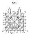
- the vane pump 1 shown in Figs. 1 to 3 in accordance with an embodiment of the present invention includes a casing 10 having a rotor chamber 2 in which a rotor 3 is accommodated eccentrically.
- a plurality of vanes 4 each having a leading end that makes sliding contact with an inner peripheral surface 2a of the rotor chamber 2 is mounted to the rotor 3.
- the casing 10 is provided with an inlet port 6 and an outlet port 7 leading to the rotor chamber 2.
- a thrust direction of the rotor 3 of the embodiment of the present invention runs vertically.
- the casing 10 that accommodates the rotor 3 therein is formed of an upper case 11 positioned above the rotor 3 and a lower case 12 arranged below the rotor 3, both of which are combined together with a packing 13 interposed therebetween.
- Reference numeral 14 in Fig. 1 designates fastener holes through which fasteners are inserted to couple the upper case 11 and the lower case 12 together.
- the upper case 11 has an upper recess 15 upwardly recessed from a coupling surface thereof coupled to the lower case 12.
- the lower case 12 has a lower recess 16 downwardly recessed from a coupling surface thereof coupled to the upper case 11.
- the upper recess 15 and the lower recess 16 are combined together to form the rotor chamber 2.
- the rotor 3 has an upper portion positioned in the upper recess 15 and a lower portion lying in the lower recess 16.
- the upper recess 15 has an inner diameter greater than an outer diameter of the rotor 3
- the lower recess 16 has an inner diameter substantially the same as the outer diameter of the rotor 3.
- the lower recess 16 is formed to have an inner diameter smaller than that of the upper recess 15, so that, when the upper case 11 and the lower case 12 are combined together, the lower recess 16 is positioned eccentrically from the upper recess 15 just like the rotor 3.
- a ring member 17 is fitted to an inner periphery of the upper recess 15 in such a way that an inner peripheral surface of the ring member 17 forms the inner peripheral surface 2a of the rotor chamber 2.
- the inner peripheral surface 2a may be readily changed into an arbitrary shape such as an elliptical shape or the like when seen in the thrust direction of the rotor 3 by varying the shape of the inner peripheral shape of the inner circumference of the ring member 17.
- formed in the upper case 11 are the inlet port 6 through which the working fluid is drawn into the working compartments 5 and the outlet port 7 through which the working fluid is discharged from the working compartments 5.
- the inlet port 6 and the outlet port 7 are in communication with the rotor chamber 2, i.e., the working compartments 5, via though-holes 17a.
- a stator 23 near an inner bottom surface of the lower recess 16.
- the rotor 3 has a central bearing portion 18 and is formed into a circular shape when seen in the thrust direction.
- a plurality of (four, in the present embodiment) vane grooves 19 are radially formed in an upper portion of the rotor 3 and a magnetic body 22 made of magnet is integrally attached to a lower portion of the rotor 3.
- a sliding contact protrusion 8 is formed throughout the peripheral length excepting the vane grooves 19.
- the bearing portion 18 of the rotor 3 is rotatably fitted to a rotating shaft 20 vertically extending through the rotor chamber 2, whereby the rotor 3 is rotatably arranged within the rotor chamber 2 in such a fashion that the outer peripheral surface 3a of the rotor 3 faces the inner peripheral surface 2a of the rotor chamber 2 and the thrust surface (top surface 3b) of the rotor 3 faces an inner ceiling surface 2b of the rotor chamber 2, which is a bottom surface of the upper recess 15.
- the rotating shaft 20 is non-rotatably secured to shaft fixing portions 21 provided at an off-centered position of the inner ceiling surface 2b of the rotor chamber 2 and a central position of the inner bottom surface of the lower recess 16.
- the vanes 4 are inserted into the respective vane grooves 19 of the rotor 3 so that the vanes 4 can slidably move in the radial direction of the rotor 3.
- the respective vanes 4 are free to protrude above and retreat below the outer peripheral surface 3a of the rotor 3.
- a sliding contact protrusion 24 that makes contact with the inner ceiling surface 2b of the rotor chamber 2 at its top surface is formed to protrude upwardly over an extent greater than the maximum radial protruding length of each of the vanes 4 from the outer peripheral surface 3a of the rotor 3.
- the magnetic body 22 and the stator 23 are placed adjacent to other when the rotor 3 is arranged in the rotor chamber 2.
- the magnetic body 22 and the stator 23 constitute a driving part for rotationally driving the rotor 3 in one direction as indicated by an arrow "a" in Fig. 1.
- the driving part when an electric current is inputted to the stator 23 from a power source (not shown), the driving part generates a torque by the magnetic interaction between the stator 23 and the magnetic body 22.
- the magnetic body 22 and the rotor 3 are rotatably driven by the torque thus generated.
- the protruded end surface of the sliding contact protrusion 8 of the rotor 3 and the protruded end surface of the sliding contact protrusion 24 of each of the vanes 4 are adapted to make sliding contact with the inner ceiling surface 2b of the rotor chamber 2 that faces the top surface 3b of the rotor 3.
- the working fluid within the respective working compartments 5 is prevented from leaking through the gap between the thrust surface of the rotor 3 and the inner ceiling surface 2b of the rotor chamber 2.
- the respective vanes 4 are protruded radially outward from the outer peripheral surface 3a of the rotor 3 under the influence of a centrifugal force exerted by rotation of the rotor 3. Therefore, the leading ends of the vanes 4 can make sliding contact with the inner peripheral surface 2a of the rotor chamber 2.
- the rotor chamber 2 is divided into a plurality of the working compartments 5, each of which is surrounded by the inner surfaces (the inner peripheral surface 2a, the inner ceiling surface 2b, etc.) of the rotor chamber 2, the outer peripheral surface 3a of the rotor 3 and the vanes 4.
- the distance between the inner peripheral surface 2a of the rotor chamber 2 and the outer peripheral surface 3a of the rotor 3 varies with the angular positions of the rotor 3 and, similarly, the protruding amount of the vanes 4 relative to the rotor 3 varies depending on the angular positions of the rotor 3.
- the rotation of the rotor 3 moves the respective working compartments 5 in the rotating direction of the rotor 3, during which time the volume of each working compartment 5 is varied between its lower and upper limits. That is, when each of the working compartments 5 is positioned to communicate with the inlet port 6, the volume thereof is increased with the rotation of the rotor 3. When each of the working compartments 5 is positioned to communicate with the outlet port 7, the volume thereof is reduced with the rotation of the rotor 3. Therefore, if the rotor 3 is rotatably driven, the working fluid is drawn into the working compartment 5 communicating with the inlet port 6 and then is pressurized in the working compartment 5, to thereby discharge the working fluid through the outlet port 7. This realizes the function of a pump.
- a cutout portion 27 is formed only on the trailing side of the leading end portion of each of the vanes 4, among the leading side of the rotating direction (the side of the leading end portion indicated by an arrow "a” in Fig. 1) and the trailing side (the side of the leading end portion indicated by an arrow "b” in Fig. 1). Therefore, the leading end can be made smaller in circumferential width than the base end portion of each of the vanes 4, the circumferential width W being a width in a direction perpendicular to both of the protruding direction of each of the vanes 4 and the thrust direction of the rotor 3 with such a configuration.
- the circumferential width W c of the cutout portion 27 may be preferably made greater than that of leading end so that the width of leading end is less than a half of the width of the base end portion of each of the vanes 4.
- each of the vanes 4 as viewed in the rotating direction of the rotor 3 is cut into a slant surface defining a periphery of the cutout portion 27.
- the cutout portion 27 is formed by cutting the trailing side surface of the leading end portion of each of the vanes 4 into a flat slant surface 27a so that, when viewed in the thrust direction of the rotor 3, the flat slant surface 27a extends toward the base end of each of the vanes 4 but outwardly in the width direction of each of the vanes 4 (the direction perpendicular to the protruding direction of each of the vanes 4 when viewed in the thrust direction of the rotor 3).
- the flat slant surface 27a is parallel to the thrust direction and is inclined against the protruding direction of each of the vanes 4 while being contiguous to the leading end surface S LE thereof.
- the leading end surface S LE of each of the vanes 4 in sliding contact with the inner peripheral surface 2a of the rotor chamber 2 at the leading side portion of each of the vanes as viewed in the rotating direction of the rotor 3 remains perpendicular to the protruding direction of each of the vanes 4.
- the leading side surface S Ls of each of the vanes 4 as viewed in the rotating direction of the rotor 3 is kept perpendicular to the width direction of each of the vanes 4.
- each of the vanes 4 By forming the cutout portion 27 in the leading end portion of each of the vanes 4 to make the leading end smaller in width than the cutout portion 27 and the base end portion of the corresponding vane 4, it is possible to increase the width W B of the base end portion of each of the vanes 4 which is slidably received in each of the vane grooves 19. This makes it possible to increase the strength of the vanes 4 and to make the vanes 4 less susceptible to a dimensional error of themselves and the vane grooves 19, thereby assuring stable movement of the vanes 4 in the radial direction of the rotor 3. Furthermore, the leading end of each of the vanes 4 having a reduced width W E can be brought into close contact with the inner peripheral surface 2a of the rotor chamber 2 having a circular cross section, which helps improve pump efficiency.
- the cutout portion 27 is formed only on the trailing side of the leading end portion of each of the vanes 4.
- the cutout portion 27 may be formed only on the leading side or both on the leading and the trailing side of the leading end portion of each of the vanes 4.
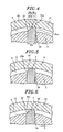
- the cutout portion 27 of each of the vanes 4 is formed by cutting the leading end portion of each of the vanes 4 into the flat slant surface 27a.
- the cutout portion 27 may be formed by cutting the leading end portion of each of the vanes 4 into a smoothly curved surface (not shown) so that the smoothly curved surface can extend toward the base end of each of the vanes 4 but outwardly in the width direction of each of the vanes 4 when viewed in the thrust direction of the rotor 3.
- the smoothly curved surface may be preferably contiguous to the leading end surface S LE and is parallel to the thrust direction.
- the cutout portion 27 of each of the vanes 4 may also be formed of a plurality of small slant surfaces 27b arranged parallel to the thrust direction of the rotor 3.
- the small slant surfaces 27b are inclined so that each of the small slant surfaces 27b can extend toward the base end of each of the vanes 4 but outwardly in the width direction of each of the vanes 4 when viewed in the thrust direction of the rotor 3.
- the small slant surfaces 27b are formed in such a fashion that the closer to the leading end of each of the vanes 4 the small slant surfaces 27b lie, the greater inclination angle the small slant surfaces 27b make with respect to the protruding direction of each of the vanes 4. That is, the small slant surface 27b disposed closer to the base end of each of the vanes 4 is more parallel to the protruding direction thereof.
- the cutout portion 27 is formed only on the trailing side of the leading end portion of each of the vanes 4 as shown in Figs. 4 and 5, it is preferable that the leading side end corner of each of the vanes 4 as viewed in the rotating direction of the rotor 3 is chamfered to form a beveled portion 28, as illustrated in Fig. 6.
- the base end side edge of the beveled portion 28 lies closer to the leading end of each of the vanes 4 than does the base end side edge of the cutout portion 28.
- the beveled portion 28 may be of either a flat slant surface or a curved surface.
- each of the vanes 4 By chamfering the leading side end corner of each of the vanes 4 as viewed in the rotating direction of the rotor 3 to form the beveled portion 28 in this way, it is possible to further reduce the width W E of the leading end of each of the vanes 4. This makes it possible to bring the leading end of each of the vanes 4 into closer sliding contact with the inner peripheral surface 2a of the rotor chamber 2 having a circular cross section and also to reduce the resistance against sliding movement of each of the vanes 4.
- the vanes 4 are protruded outwardly by the centrifugal force exerted by the rotation of the rotor 3.
- spring members 26 that outwardly bias the vanes 4 may be inserted into the vane grooves 19 to ensure that the leading ends of the vanes 4 can make reliable sliding contact with the inner peripheral surface 2a of the rotor chamber 2 without resort to the rotating speed of the rotor 3.
- the protruding end surface of the sliding contact protrusion 8 protruded in the peripheral end portion of the thrust surface of the rotor 3 and protruding the end surface of the sliding contact protrusion 24 of each of the vanes 4 are adapted to make sliding contact with the flat ceiling surface 2b of the rotor chamber 2.
- the means for bringing the thrust surface of the rotor 3 into sliding contact with the ceiling surface 2b of the rotor chamber 2 is not limited thereto. For example, as shown in Figs.
- the thrust surface of the rotor 3 and the top surfaces of the vanes 4 may be made flat, and a sliding contact protrusion 8' may be formed on the ceiling surface 2b of the rotor chamber 2 in alignment with the trajectory of the peripheral end portion of the thrust surface of the rotor 3 and the vanes 4 so that the protruding end surface of sliding contact protrusion 8' can make sliding contact with the peripheral end portion of the thrust surface of the rotor 3 and the vanes 4.
- the driving part for rotatably driving the rotor 3 is formed of the stator 23 and the magnetic body 22 that magnetically interact with each other.
- the driving part a structure in which a shaft fixed to the rotor 3 is rotatably driven by an electric motor.
- the cutout portion 27 may be formed such that, when the vanes 4 are protruded farthest from the outer peripheral surface of the rotor 3, the base end side edge of the cutout portion 27 is positioned closer to the central shaft of the rotor 3 than is the outer peripheral surface of the rotor 3.
- the whole part of the cutout portion 27 may be positioned radially outwardly of the outer peripheral surface of the rotor 3 when the vanes 4 are protruded farthest from the outer peripheral surface of the rotor 3.
Landscapes
- Engineering & Computer Science (AREA)
- Mechanical Engineering (AREA)
- General Engineering & Computer Science (AREA)
- Rotary Pumps (AREA)
Applications Claiming Priority (1)
| Application Number | Priority Date | Filing Date | Title |
|---|---|---|---|
| JP2006314629A JP2008128116A (ja) | 2006-11-21 | 2006-11-21 | ベーンポンプ |
Publications (1)
| Publication Number | Publication Date |
|---|---|
| EP1925777A1 true EP1925777A1 (de) | 2008-05-28 |
Family
ID=39047506
Family Applications (1)
| Application Number | Title | Priority Date | Filing Date |
|---|---|---|---|
| EP07022034A Withdrawn EP1925777A1 (de) | 2006-11-21 | 2007-11-13 | Flügelzellenpumpe |
Country Status (6)
| Country | Link |
|---|---|
| US (1) | US7566211B2 (de) |
| EP (1) | EP1925777A1 (de) |
| JP (1) | JP2008128116A (de) |
| KR (1) | KR20080046126A (de) |
| CN (2) | CN100580254C (de) |
| TW (1) | TWI356130B (de) |
Families Citing this family (8)
| Publication number | Priority date | Publication date | Assignee | Title |
|---|---|---|---|---|
| CN101813085A (zh) * | 2010-03-22 | 2010-08-25 | 黄武源 | 自吸节能高效型水泵 |
| DE102010039344A1 (de) * | 2010-08-16 | 2012-02-16 | Joma-Polytec Gmbh | Flügelzellenpumpe |
| CN102425548A (zh) * | 2011-12-22 | 2012-04-25 | 上海成峰流体设备有限公司 | 叶片泵的叶片结构 |
| US9874210B2 (en) | 2015-10-29 | 2018-01-23 | Ford Global Technologies, Llc | Vane oil pump |
| NL2016728B1 (en) * | 2016-05-03 | 2017-11-10 | Actuant Corp | Pump unit with integrated piston pump and electric motor. |
| CN109386461B (zh) * | 2017-08-04 | 2022-10-25 | 罗伯特·博世有限公司 | 燃油叶片泵 |
| CN110606458A (zh) * | 2019-09-10 | 2019-12-24 | 安徽德利来环保科技有限公司 | 一种车用尿素灌装设备用组件 |
| KR102378399B1 (ko) * | 2020-07-03 | 2022-03-24 | 엘지전자 주식회사 | 로터리 압축기 |
Citations (7)
| Publication number | Priority date | Publication date | Assignee | Title |
|---|---|---|---|---|
| US1543155A (en) | 1922-04-20 | 1925-06-23 | Walter Schindler | Lubrication of parts rotating at high speed |
| GB1537522A (en) | 1975-06-24 | 1978-12-29 | Nippon Piston Ring Co Ltd | Vane type rotary fluid pumps or compressors |
| US4174931A (en) | 1976-12-17 | 1979-11-20 | Diesel Kiki Company, Ltd. | Vane for rotary compressor |
| JPS57137680A (en) | 1981-02-20 | 1982-08-25 | Matsushita Electric Ind Co Ltd | Rotary compressor |
| JPS6111401A (ja) * | 1984-06-26 | 1986-01-18 | Mitsubishi Heavy Ind Ltd | 回転型流体機械 |
| JPS62291488A (ja) | 1986-06-11 | 1987-12-18 | Toshiba Corp | 油回転真空ポンプ |
| JP2006194090A (ja) * | 2005-01-11 | 2006-07-27 | Matsushita Electric Ind Co Ltd | ベーンロータリ型空気ポンプ |
Family Cites Families (14)
| Publication number | Priority date | Publication date | Assignee | Title |
|---|---|---|---|---|
| US1965388A (en) * | 1932-01-09 | 1934-07-03 | Racine Tool & Machine Company | Rotary pump |
| US4163635A (en) * | 1975-06-24 | 1979-08-07 | Nippon Piston Ring Kabushiki Kaisha | Vane type rotary fluid pumps or compressors |
| JPS5385715U (de) * | 1976-12-17 | 1978-07-14 | ||
| JPS55161989A (en) * | 1979-06-05 | 1980-12-16 | Atsugi Motor Parts Co Ltd | Vane pump |
| JPS58104381U (ja) * | 1981-12-08 | 1983-07-15 | セイコ−精機株式会社 | 気体圧縮機 |
| JPS5952196U (ja) * | 1982-09-30 | 1984-04-05 | カヤバ工業株式会社 | ロ−タリコンプレツサ |
| JPS6187987A (ja) | 1984-10-05 | 1986-05-06 | Mitsubishi Motors Corp | ベ−ンポンプ |
| JPS614886A (ja) * | 1984-06-19 | 1986-01-10 | Matsushita Electric Ind Co Ltd | ベ−ン回転式圧縮機 |
| JPS61149791U (de) * | 1985-03-06 | 1986-09-16 | ||
| JPS6298787U (de) * | 1985-12-11 | 1987-06-23 | ||
| JPH0252988U (de) * | 1988-10-06 | 1990-04-17 | ||
| US6030191A (en) | 1997-08-20 | 2000-02-29 | Delaware Capital Formation, Inc. | Low noise rotary vane suction pump having a bleed port |
| JP2000130373A (ja) * | 1998-10-23 | 2000-05-12 | Sanwa Seiki Co Ltd | 真空ポンプ |
| JP2003343462A (ja) * | 2002-05-23 | 2003-12-03 | Toyoda Mach Works Ltd | ベーン式バキュームポンプ |
-
2006
- 2006-11-21 JP JP2006314629A patent/JP2008128116A/ja active Pending
-
2007
- 2007-11-13 EP EP07022034A patent/EP1925777A1/de not_active Withdrawn
- 2007-11-14 US US11/984,130 patent/US7566211B2/en not_active Expired - Fee Related
- 2007-11-15 TW TW096143244A patent/TWI356130B/zh not_active IP Right Cessation
- 2007-11-20 CN CN200710192778A patent/CN100580254C/zh not_active Expired - Fee Related
- 2007-11-20 CN CNU2007201932795U patent/CN201206546Y/zh not_active Expired - Fee Related
- 2007-11-21 KR KR1020070119357A patent/KR20080046126A/ko not_active Ceased
Patent Citations (7)
| Publication number | Priority date | Publication date | Assignee | Title |
|---|---|---|---|---|
| US1543155A (en) | 1922-04-20 | 1925-06-23 | Walter Schindler | Lubrication of parts rotating at high speed |
| GB1537522A (en) | 1975-06-24 | 1978-12-29 | Nippon Piston Ring Co Ltd | Vane type rotary fluid pumps or compressors |
| US4174931A (en) | 1976-12-17 | 1979-11-20 | Diesel Kiki Company, Ltd. | Vane for rotary compressor |
| JPS57137680A (en) | 1981-02-20 | 1982-08-25 | Matsushita Electric Ind Co Ltd | Rotary compressor |
| JPS6111401A (ja) * | 1984-06-26 | 1986-01-18 | Mitsubishi Heavy Ind Ltd | 回転型流体機械 |
| JPS62291488A (ja) | 1986-06-11 | 1987-12-18 | Toshiba Corp | 油回転真空ポンプ |
| JP2006194090A (ja) * | 2005-01-11 | 2006-07-27 | Matsushita Electric Ind Co Ltd | ベーンロータリ型空気ポンプ |
Also Published As
| Publication number | Publication date |
|---|---|
| TWI356130B (en) | 2012-01-11 |
| CN100580254C (zh) | 2010-01-13 |
| HK1115908A1 (zh) | 2008-12-12 |
| CN201206546Y (zh) | 2009-03-11 |
| CN101187369A (zh) | 2008-05-28 |
| KR20080046126A (ko) | 2008-05-26 |
| JP2008128116A (ja) | 2008-06-05 |
| US7566211B2 (en) | 2009-07-28 |
| US20080118384A1 (en) | 2008-05-22 |
| TW200837281A (en) | 2008-09-16 |
Similar Documents
| Publication | Publication Date | Title |
|---|---|---|
| US7566211B2 (en) | Vane pump having vanes with a cutout portion | |
| US5527149A (en) | Extended range regenerative pump with modified impeller and/or housing | |
| US7628594B2 (en) | Vane pump having a labyrinth seal and gap between a top surface of a rotor and a ceiling surface of a rotor chamber that is formed between upper and lower cases | |
| EP2447534A2 (de) | Elektrisch angetriebene Pumpe | |
| KR101146780B1 (ko) | 베인셀펌프 | |
| EP1467101B1 (de) | Flügelzellenpumpe | |
| US7566212B2 (en) | Vane pump with blade base members | |
| JP3982262B2 (ja) | 電動燃料ポンプ | |
| CN112912625A (zh) | 叶轮泵 | |
| JP6670119B2 (ja) | ベーンポンプ | |
| EP2982865B1 (de) | Unterdruckpumpe | |
| US5409360A (en) | Vacuum pumps | |
| CN110325740B (zh) | 汽车液体摆式叶片泵 | |
| HK1115908B (en) | Vane pump | |
| JPH0329995B2 (de) | ||
| JP4976826B2 (ja) | ベーンポンプ | |
| CN214626692U (zh) | 泵及其转子 | |
| JP5238922B2 (ja) | スクロール流体機械 | |
| JP4811243B2 (ja) | ベーンポンプ | |
| KR101811695B1 (ko) | 회전통체를 갖는 베인형 펌프 | |
| JP2008223549A (ja) | ベーンポンプ | |
| JP2010048182A (ja) | ベーンポンプ | |
| JP2008128203A (ja) | ベーンポンプ | |
| KR20200081272A (ko) | 압축기 | |
| KR20000042630A (ko) | 헬리컬 블레이드형 펌프 |
Legal Events
| Date | Code | Title | Description |
|---|---|---|---|
| PUAI | Public reference made under article 153(3) epc to a published international application that has entered the european phase |
Free format text: ORIGINAL CODE: 0009012 |
|
| AK | Designated contracting states |
Kind code of ref document: A1 Designated state(s): AT BE BG CH CY CZ DE DK EE ES FI FR GB GR HU IE IS IT LI LT LU LV MC MT NL PL PT RO SE SI SK TR |
|
| AX | Request for extension of the european patent |
Extension state: AL BA HR MK RS |
|
| 17P | Request for examination filed |
Effective date: 20081113 |
|
| AKX | Designation fees paid |
Designated state(s): AT BE BG CH CY CZ DE DK EE ES FI FR GB GR HU IE IS IT LI LT LU LV MC MT NL PL PT RO SE SI SK TR |
|
| RAP1 | Party data changed (applicant data changed or rights of an application transferred) |
Owner name: PANASONIC ELECTRIC WORKS CO., LTD. |
|
| RAP1 | Party data changed (applicant data changed or rights of an application transferred) |
Owner name: PANASONIC CORPORATION |
|
| STAA | Information on the status of an ep patent application or granted ep patent |
Free format text: STATUS: THE APPLICATION HAS BEEN WITHDRAWN |
|
| 18W | Application withdrawn |
Effective date: 20120418 |