EP1925953A1 - Film de transmission de la lumière, son procédé de fabrication et affichage à cristaux liquides - Google Patents
Film de transmission de la lumière, son procédé de fabrication et affichage à cristaux liquides Download PDFInfo
- Publication number
- EP1925953A1 EP1925953A1 EP06797988A EP06797988A EP1925953A1 EP 1925953 A1 EP1925953 A1 EP 1925953A1 EP 06797988 A EP06797988 A EP 06797988A EP 06797988 A EP06797988 A EP 06797988A EP 1925953 A1 EP1925953 A1 EP 1925953A1
- Authority
- EP
- European Patent Office
- Prior art keywords
- light
- prism
- refraction
- index
- dimensional structure
- Prior art date
- Legal status (The legal status is an assumption and is not a legal conclusion. Google has not performed a legal analysis and makes no representation as to the accuracy of the status listed.)
- Withdrawn
Links
Images







Classifications
-
- G—PHYSICS
- G02—OPTICS
- G02B—OPTICAL ELEMENTS, SYSTEMS OR APPARATUS
- G02B5/00—Optical elements other than lenses
- G02B5/30—Polarising elements
- G02B5/3083—Birefringent or phase retarding elements
-
- G—PHYSICS
- G02—OPTICS
- G02B—OPTICAL ELEMENTS, SYSTEMS OR APPARATUS
- G02B5/00—Optical elements other than lenses
- G02B5/04—Prisms
- G02B5/045—Prism arrays
-
- G—PHYSICS
- G02—OPTICS
- G02B—OPTICAL ELEMENTS, SYSTEMS OR APPARATUS
- G02B6/00—Light guides; Structural details of arrangements comprising light guides and other optical elements, e.g. couplings
- G02B6/0001—Light guides; Structural details of arrangements comprising light guides and other optical elements, e.g. couplings specially adapted for lighting devices or systems
- G02B6/0011—Light guides; Structural details of arrangements comprising light guides and other optical elements, e.g. couplings specially adapted for lighting devices or systems the light guides being planar or of plate-like form
- G02B6/0033—Means for improving the coupling-out of light from the light guide
- G02B6/005—Means for improving the coupling-out of light from the light guide provided by one optical element, or plurality thereof, placed on the light output side of the light guide
- G02B6/0053—Prismatic sheet or layer; Brightness enhancement element, sheet or layer
-
- G—PHYSICS
- G02—OPTICS
- G02B—OPTICAL ELEMENTS, SYSTEMS OR APPARATUS
- G02B6/00—Light guides; Structural details of arrangements comprising light guides and other optical elements, e.g. couplings
- G02B6/0001—Light guides; Structural details of arrangements comprising light guides and other optical elements, e.g. couplings specially adapted for lighting devices or systems
- G02B6/0011—Light guides; Structural details of arrangements comprising light guides and other optical elements, e.g. couplings specially adapted for lighting devices or systems the light guides being planar or of plate-like form
- G02B6/0033—Means for improving the coupling-out of light from the light guide
- G02B6/0056—Means for improving the coupling-out of light from the light guide for producing polarisation effects, e.g. by a surface with polarizing properties or by an additional polarizing elements
-
- G—PHYSICS
- G02—OPTICS
- G02F—OPTICAL DEVICES OR ARRANGEMENTS FOR THE CONTROL OF LIGHT BY MODIFICATION OF THE OPTICAL PROPERTIES OF THE MEDIA OF THE ELEMENTS INVOLVED THEREIN; NON-LINEAR OPTICS; FREQUENCY-CHANGING OF LIGHT; OPTICAL LOGIC ELEMENTS; OPTICAL ANALOGUE/DIGITAL CONVERTERS
- G02F1/00—Devices or arrangements for the control of the intensity, colour, phase, polarisation or direction of light arriving from an independent light source, e.g. switching, gating or modulating; Non-linear optics
- G02F1/01—Devices or arrangements for the control of the intensity, colour, phase, polarisation or direction of light arriving from an independent light source, e.g. switching, gating or modulating; Non-linear optics for the control of the intensity, phase, polarisation or colour
- G02F1/13—Devices or arrangements for the control of the intensity, colour, phase, polarisation or direction of light arriving from an independent light source, e.g. switching, gating or modulating; Non-linear optics for the control of the intensity, phase, polarisation or colour based on liquid crystals, e.g. single liquid crystal display cells
- G02F1/133—Constructional arrangements; Operation of liquid crystal cells; Circuit arrangements
- G02F1/1333—Constructional arrangements; Manufacturing methods
- G02F1/1335—Structural association of cells with optical devices, e.g. polarisers or reflectors
- G02F1/1336—Illuminating devices
- G02F1/133602—Direct backlight
- G02F1/133606—Direct backlight including a specially adapted diffusing, scattering or light controlling members
-
- G—PHYSICS
- G02—OPTICS
- G02F—OPTICAL DEVICES OR ARRANGEMENTS FOR THE CONTROL OF LIGHT BY MODIFICATION OF THE OPTICAL PROPERTIES OF THE MEDIA OF THE ELEMENTS INVOLVED THEREIN; NON-LINEAR OPTICS; FREQUENCY-CHANGING OF LIGHT; OPTICAL LOGIC ELEMENTS; OPTICAL ANALOGUE/DIGITAL CONVERTERS
- G02F1/00—Devices or arrangements for the control of the intensity, colour, phase, polarisation or direction of light arriving from an independent light source, e.g. switching, gating or modulating; Non-linear optics
- G02F1/01—Devices or arrangements for the control of the intensity, colour, phase, polarisation or direction of light arriving from an independent light source, e.g. switching, gating or modulating; Non-linear optics for the control of the intensity, phase, polarisation or colour
- G02F1/13—Devices or arrangements for the control of the intensity, colour, phase, polarisation or direction of light arriving from an independent light source, e.g. switching, gating or modulating; Non-linear optics for the control of the intensity, phase, polarisation or colour based on liquid crystals, e.g. single liquid crystal display cells
- G02F1/133—Constructional arrangements; Operation of liquid crystal cells; Circuit arrangements
- G02F1/1333—Constructional arrangements; Manufacturing methods
- G02F1/1335—Structural association of cells with optical devices, e.g. polarisers or reflectors
- G02F1/1336—Illuminating devices
- G02F1/13362—Illuminating devices providing polarized light, e.g. by converting a polarisation component into another one
-
- G—PHYSICS
- G02—OPTICS
- G02F—OPTICAL DEVICES OR ARRANGEMENTS FOR THE CONTROL OF LIGHT BY MODIFICATION OF THE OPTICAL PROPERTIES OF THE MEDIA OF THE ELEMENTS INVOLVED THEREIN; NON-LINEAR OPTICS; FREQUENCY-CHANGING OF LIGHT; OPTICAL LOGIC ELEMENTS; OPTICAL ANALOGUE/DIGITAL CONVERTERS
- G02F1/00—Devices or arrangements for the control of the intensity, colour, phase, polarisation or direction of light arriving from an independent light source, e.g. switching, gating or modulating; Non-linear optics
- G02F1/01—Devices or arrangements for the control of the intensity, colour, phase, polarisation or direction of light arriving from an independent light source, e.g. switching, gating or modulating; Non-linear optics for the control of the intensity, phase, polarisation or colour
- G02F1/13—Devices or arrangements for the control of the intensity, colour, phase, polarisation or direction of light arriving from an independent light source, e.g. switching, gating or modulating; Non-linear optics for the control of the intensity, phase, polarisation or colour based on liquid crystals, e.g. single liquid crystal display cells
- G02F1/133—Constructional arrangements; Operation of liquid crystal cells; Circuit arrangements
- G02F1/1333—Constructional arrangements; Manufacturing methods
- G02F1/1335—Structural association of cells with optical devices, e.g. polarisers or reflectors
- G02F1/1336—Illuminating devices
- G02F1/133602—Direct backlight
- G02F1/133606—Direct backlight including a specially adapted diffusing, scattering or light controlling members
- G02F1/133607—Direct backlight including a specially adapted diffusing, scattering or light controlling members the light controlling member including light directing or refracting elements, e.g. prisms or lenses
Definitions
- the present invention relates to a light-transmitting film including continuously aligned three-dimensional structures on one of the surfaces, a method of forming the light-transmitting film, and a liquid crystal display.
- Liquid crystal displays consume less electric power and can be formed small and thin compared with cathode ray tubes (CRTs). Recently, liquid crystal displays of various sizes are put to use, such as small devices including mobile phones, digital cameras, personal digital assistants (PDAs) and large devices including liquid crystal televisions.
- LCDs liquid crystal displays
- PDAs personal digital assistants
- a transmissive liquid crystal display includes a liquid crystal display panel formed by sandwiching a liquid crystal layer with a pair of transparent substrates, first and second polarizers disposed on the light incident side and the light emission side, respectively, of the liquid crystal display panel, and a backlight unit that functions as an illumination light source.
- the backlight unit may be a direct light type in which a light source is disposed directly below the liquid crystal display panel or an edge light type that uses a light-guiding plate.
- a configuration is known in which a light-transmitting film known as a luminance improvement film is interposed between the backlight unit and the liquid crystal display panel (for example, refer to Japanese Patent No. 3158555 ).
- the luminance improvement film is made of a prism sheet having prisms with triangular cross-sections periodically aligned at a fine pitch on a first side and collects light by vertically emitting the light from the backlight to the front side.
- the index of refraction is isotropic and the light emitted from the prism sheet is usually not polarized, about half of the light emitted from the prism sheet is absorbed by the first polarizer disposed on the light incident side of the liquid crystal display panel. Consequently, there is a problem in that the illumination light from the backlight cannot be used efficiently and luminance cannot be improved.
- the production cost of the liquid crystal display apparatus increases and the number of components increases. Thus, it becomes difficult to reduce and size and thickness of the apparatus.
- the function is not necessarily sufficient in that, for example, part of the polarized component in the absorption axis direction of the first polarizer leaks.
- the present invention has been conceived in light of the above-identified problem and provides a light-transmitting film that has both a light-collecting function and a predetermined polarization split function, a method of forming a light-transmitting film, and a liquid crystal display apparatus.
- the light-transmitting film according to the present invention includes a three-dimensional structure disposed continuously on a first surface, and the index of refraction in the extension direction of the three-dimensional structure and the index of refraction in the alignment direction of the three-dimensional structure differ.
- the extension direction of the three-dimensional structure is not limited to one direction.
- the extension directions of the three-dimensional structure may be differed to that a plurality of extension directions are two-dimensionally arranged.
- the three-dimensional structure according to the present invention includes a structure such as a prism or a lenticular lens.
- the prism is formed with, for example, a cross-sectional shape of triangles having a 90° (degrees) apex angle.
- the amount of return light of the polarization component oscillating in the extension direction of the prism is greater than that of the polarization component oscillating in the alignment direction of the prism.
- the light-transmitting film according to the present invention having refraction anisotropy in the extension direction and the alignment direction of the three-dimensional structure is formed by carrying out a"step of forming a resin film having the three-dimensional structure on the first surface; and a step of stretching the resin film in an extension direction of the three-dimensional structure and generating a difference in the index of refraction in the extension direction of the three-dimensional structure and the index of refraction in the alignment direction of the three-dimensional structure.
- the stretching direction of the resin film is set to the extension direction of the three-dimensional structure to reduce the change in the optical characteristic due to the change in the shape of the prism before and after stretching.
- the index of refraction in the extension direction is set greater than the index of refraction in the alignment direction of the three-dimensional structure, it is preferable to select a material that has a great index of refraction in the extension direction for the structuring material of the light-transmitting film.
- a material that has a great index of refraction in the stretching direction includes co-polymers such as polyethylene terephthalate (PET), polyethylene naphthalate (PEN), a PET-PEN mixture, or a PET-PEN co-polymer, polycarbonate, polyvinyl alcohol, polyester, polyvinylidene fluoride, polypropylene, and polyamide.
- co-polymers such as polyethylene terephthalate (PET), polyethylene naphthalate (PEN), a PET-PEN mixture, or a PET-PEN co-polymer, polycarbonate, polyvinyl alcohol, polyester, polyvinylidene fluoride, polypropylene, and polyamide.
- a material that has a small index of refraction in the stretching direction includes, for example, methacrylic resin, polystyrene-based resin, styrene-methyl methacrylate co-polymer, and a mixture thereof.
- the light-transmitting film according to the present invention is used as a luminance-improvement film for a liquid crystal display apparatus, either one of the following two structures may be employed.
- the light-transmitting film is formed so that the index of refraction in the extension direction of the three-dimensional structure is greater than the index of refraction in the alignment direction and the angle formed by the alignment direction of the three-dimensional structure and the light-transmission axis of the polarizer, among the pair of polarizers, disposed on the light incident side of the liquid crystal display panel set from 0° to 45°.
- the light-transmitting film is formed so that the index of refraction in the alignment direction of the three-dimensional structure is greater than the index of refraction in the extension direction and the angle formed by the extension direction of the three-dimensional structure and the light-transmission axis of the polarizer, among the pair of polarizers, disposed on the light incident side of the liquid crystal display panel set from 0° to 45°.
- the emission light from the light-transmitting film can be efficiently emitted at the liquid crystal display panel. Therefore, the backlight beams can be used efficiently, and the luminance of the liquid crystal display apparatus can be improved.
- the extension direction of the three-dimensional structure and the alignment direction have anisotropy in the indices of refraction, not only a light-collecting effect, but also a predetermined polarization split effect can be achieved. Therefore, without using optical elements, such as a reflective polarizer, the luminance improvement effect of the liquid crystal display apparatus can be increased, and the number of components and production cost can be decreased.
- Fig. 1 is a schematic view of a liquid crystal display apparatus 10 including a light-transmitting film according to an embodiment of the present invention. First, the overall structure of the liquid crystal display apparatus 10 will be briefly described.
- the liquid crystal display apparatus 10 includes a liquid crystal display panel 11, a first polarizer 12A and a second polarizer 12B sandwiching the liquid crystal display panel 11, a prism sheet 13, a diffuser 14, and a backlight unit 15.
- the liquid crystal display panel 11 has a structure in which a liquid crystal layer is interposed between a pair of transparent substrates.
- liquid crystal material for a driving mode having an excellent viewing angle characteristics such as vertical alignment (VA) and in-plane switching (IPS).
- VA vertical alignment
- IPS in-plane switching
- the first polarizer 12A is a polarizer disposed on the light incident side of the liquid crystal display panel 11
- the second polarizer 12B is a polarizer disposed on the light emission side of the liquid crystal display panel 11.
- the orientation of a transmission axis a of light is determined in accordance with the relationship between the magnitudes of the index of refraction in the alignment direction of the prisms on the prism sheet 13 (hereinafter this is referred to as the "prism alignment direction”) and the index of refraction in the extension direction of the prisms (hereinafter this is referred to as the "prism extension direction").
- the effect is maximized when the direction of the transmission axis a of light of the first polarizer 12A is set to the prism alignment direction, as shown in Fig. 1 .
- the angle formed by the transmission axis a and the prism alignment direction may be increased. In such a case, to improve the front luminance, the angle must be between 0° to 45° and more preferably should be between 0° to 20°.
- the effect is maximized when the direction of the transmission axis a of the first polarizer 12A is set to the prism extension direction.
- the angle formed by the transmission axis a and the prism extension direction may be increased. In such a case, to improve the front luminance, the angle must be between 0° to 45° and more preferably should be between 0° to 20°.
- the prism sheet 13 corresponds to the light-transmitting film according to the present invention and is used as a luminance improvement film for improving the front luminance of the liquid crystal display apparatus 10.
- the prism sheet 13 is disposed on the light emission side of the diffuser 14 that diffuses and emits illumination light (hereinafter also referred to as "backlight beams") from the backlight unit 15 and, as described below, has a collecting function and a predetermined polarization split function.
- the backlight unit 15 is configured as a direct light type including a plurality of linear light sources 16 and a reflector 17. However, the backlight unit 15 is not limited thereto and may be configured as a side-edge type using a light-guiding plate.
- the light sources 16 are linear light sources, such as cold cathode fluorescent lamps (CCFLs). Instead, however, point light sources, such as light emitting diodes (LEDs) may be used.
- CCFLs cold cathode fluorescent lamps
- LEDs light emitting diodes
- Fig. 2 is a schematic view of the entire structure of the prism sheet 13.
- the prism sheet 13 is made of light-transmitting resin material and has, on a first side, a prism structure surface 13a on which uniform columnar prisms having triangular cross-sections are continuously aligned in a first direction (Y direction).
- the prisms included in the prism structure surface 13a correspond to the "three-dimensional structures" according to the present invention and are each formed with the same apex angle and pitch. According to this embodiment, the prism apex angle is 90°, and the alignment pitch is, for example, 50 ⁇ m.
- a second side of the prism sheet 13 is a flat surface 13b.
- the prism structure surface 13a of the prism sheet 13 is disposed facing the light emission side (liquid crystal display panel 11 side).
- the prism sheet 13 has different indices of refraction in the prism extension direction (X direction) and the prism alignment direction (Y direction). In this way, since the prism sheet 13 has indices of refraction with in-plane anisotropy, the transmitting characteristic of the light incident on the prism sheet 13 can be changed in accordance with the polarization state.
- Fig. 3 illustrates the path of the light incident on the prism sheet 13 and, in particular, illustrates a case in which the index of refraction nx in the prism extension direction is greater than the index of refraction in the prism alignment direction (nx>ny).
- Lx represents a polarization component of a backlight beam L that oscillates in the prism extension direction (X direction)
- Ly represents a polarization component of the backlight beam L that oscillates in the prism alignment direction (Y direction).
- the X-direction polarization components Lx and the Y-direction polarization components Ly of the backlight beam are refracted at different refraction angles rx and ry, respectively, (rx ⁇ ry) and are emitted from the inclined surfaces of the prism at different emission angles ⁇ x and ⁇ y, respectively.
- the emission angle ⁇ y of the polarization components Ly is smaller than the emission ⁇ x angle of the polarization components Lx ( ⁇ x> ⁇ y).
- both of the polarization components Lx and Ly are emitted from the light emission surface (prism structure surface 13a) of the prism sheet 13.
- the indices of refraction differ in the prism extension direction (X direction) and the prism alignment direction (Y direction9, the oscillating polarization components in these directions are reflected at different degrees of reflection at an interface such as the flat surface 13b or the inclined surfaces of the prisms.
- the index of refraction nx in the prism extension direction is greater than the index of refraction ny in the prism alignment direction
- the polarization components Lx oscillating in the prism extension direction are reflected more than the Ly.
- the amount of light of the Ly is greater than that of the Lx.
- ⁇ x> ⁇ y Since the emission angles of the polarization components Lx and Ly emitted from the inclined surfaces of the prisms have a relationship ⁇ x> ⁇ y, when the incident angle of a backlight beam incident on the prism sheet 13 satisfies a predetermined condition, a complete polarization split state is achieved in which the polarization components Lx are totally reflected repeatedly at the inclined surfaces of the prisms and only the polarization components Ly are transmitted through the prism sheet 13.
- An example of this state being achieved under the condition of an incident angle ⁇ 2 is illustrated in Fig. 3 .
- the incident angle of the backlight beam to the prism sheet 13 is too small, the same state as that when the backlight beam is orthogonally incident to the flat surface 13b of the prism sheet 13 is achieved.
- the backlight beam L is totally reflected repeatedly at the inclined surfaces of the prisms and becomes a return beam that returns to the side of the backlight.
- the prism sheet 13 As described above, by providing in-plane anisotropy to the prism sheet 13, a predetermined polarization split effect can be obtained in addition to the collecting effect of backlight beams. Furthermore, the light reflected at the prism sheet 13 according to the above-described example will be reflected at the surfaces of the reflector 17 ( Fig. 1 ) and the diffuser 14 of the backlight unit 15 and will be incident on the prism sheet 13 again without being polarized. Therefore, light efficiency is increased, and the light can contribute to the improvement of front luminance.
- the prism sheet 13 according to this embodiment in formed by a step of producing a resin film having the prism structure surface 13a on the first side and a step of stretching the resin film in the prism extension direction and providing difference in the indices of refraction in the prism extension direction and the prism alignment direction.
- the method of producing the resin film is not limited, and, for example, a hot press method or a melt extrusion process may be employed. Furthermore, a prism layer may be formed on a base of a flat resin sheet. It is preferable that the resin film be producible continuously using a roll.
- the refraction anisotropy is added to the produced resin film by stretching the resin film in the prism extension direction.
- the index of refraction nx in the prism extension direction is greater than the index of refraction ny in the prism alignment direction. Therefore, as shown in Fig. 4A , by producing a resin film 23 using resin material having a great index of refraction in the stretching direction and then stretching the resin film 23 in the prism extension direction (X direction), the target prism sheet 13 is obtained.
- the stretching rate can be set appropriately in accordance with the required in-plane difference in the indices of refraction and the type of the resin film material.
- Resin material that has a great index of refraction in the stretching direction includes co-polymers such as polyethylene terephthalate (PET), polyethylene naphthalate (PEN), a mixture thereof, or a PET-PEN co-polymer, polycarbonate, polyvinyl alcohol, polyester, polyvinylidene fluoride, polypropylene, and polyamide.
- co-polymers such as polyethylene terephthalate (PET), polyethylene naphthalate (PEN), a mixture thereof, or a PET-PEN co-polymer, polycarbonate, polyvinyl alcohol, polyester, polyvinylidene fluoride, polypropylene, and polyamide.
- the stretching direction is set to the prism extension direction so as to suppress a change in the target optical characteristic caused by a change in the prism shape before and after stretching.
- Fig. 4B illustrates a change in the external shape of the prism structure surface before and after stretching, where the solid line represents before stretching and the single dotted line represents after stretching.
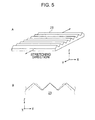
- Figs. 5A and 5B by adding refraction anisotropy to the resin film 23 by stretching it in the prism alignment direction (Y direction), the change in the external shape of the prism changes greatly, where in particular the prism apex angle and prism alignment pitch increase, and it becomes difficult to control the desired optical characteristic in a highly accurate manner.
- the double-dotted chain line represents before stretching and the solid line represents after stretching.
- Resin material that has a small index of refraction in the stretching direction may be used and then stretched in the prism extension direction.
- Resin material having a small index of refraction in the stretching direction includes methacrylic resin such as methacrylate, polystyrene resin, styrene-acrylonitrile co-polymer (AS resin), styrene-methacrylate co-polymer, and mixtures thereof.
- Fig. 6 is an overall side view of the liquid crystal display apparatus 10 illustrating the polarization state of light transmitted through the prism sheet 13, the first polarizer 12A, the liquid crystal display panel 11, and the second polarizer 12B.
- the transmission axis a of the first polarizer 12A is determined in accordance with the magnitude of the relationship between the magnitudes of the index of refraction in the prism alignment direction and the index of refraction of the stretching direction in the prism extension direction.
- Fig. 6 illustrates a case in which the index of refraction in the prism extension direction is greater than the index of refraction in the prism alignment direction, where it is preferable to dispose the transmission axis a of the first polarizer 12A in the prism alignment direction (Y direction).
- Lx represents a polarization component in the backlight beam L oscillating in the prism extension direction (X direction)
- Ly represents a polarization component in the backlight beam L oscillating in the prism alignment direction (Y direction).
- Non-polarized light that is emitted from the backlight unit 15, not shown in the drawing, and that is transmitted through the diffuser 14 is incident on the flat surface 13b of the prism sheet 13.
- the backlight beam L is collected toward the front direction at the prism sheet 13, emitted from the prism structure surface 13a, and then incident on the first polarizer 12A.
- the first polarizer 12A absorbs the Lx and transmits the Ly of the incident backlight beam L.
- the Ly transmitted through the first polarizer 12A is polarized by each pixel unit at the liquid crystal display panel 11 and is incident on the second polarizer 12B. Only polarized light of the transmitting axis of the second polarizer 12B is transmitted so as to form an image on the front surface of the panel.
- the incident angle ⁇ of the backlight beam L incident on the prism sheet 13 is not constant and has a predetermined angle distribution.
- the prism sheet 13 according to this embodiment is formed such that the index of refraction nx in the prism extension direction is greater than the index of refraction ny in the prism alignment direction. Therefore, as described with reference to Fig. 3 , with the backlight beam L transmitted through the prism sheet 13, the amount of Lx is greater than that of Ly.
- the quantitative proportion depends on the difference between the index of refraction in the prism alignment direction of the prism sheet 13 and the index of refraction in the prism extension direction and the distribution of the incident angle ⁇ of the backlight beam L incident on the prism sheet 13.
- Part of the backlight beam L reflected at the prism sheet 13 is reflected at the surface of the diffuser 14 or the reflector 17 of the backlight unit 15 and is incident on the prism sheet 13 again. Such a recycling effect is repeated to efficiently use the backlight beam L.
- the prism sheet 13 since the prism sheet 13 not has only a light collecting effect but also has a predetermined polarization split effect, the amount of emitted light of the polarization components Lx of the backlight beam L in the prism extension direction can be reduced more than the amount of emitted light of the polarization components Ly in the prism alignment direction.
- the amount of the backlight beam L absorbed at the first polarizer 12A can be reduced so as to efficiently use the backlight beam L. In this way, the extraction efficiency of the backlight beam L is increased, and the front luminance is improved.
- the thickness of the liquid crystal display apparatus can be further reduced by reducing the number of components, and the production cost can be reduced.
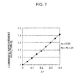
- the prism apex angle is 90°.
- the great ⁇ n is, the greater the luminance improvement rate is. Since the angular luminance distribution is determined by nx, the value can be appropriately determined by product design. In contrast, the greater ny is than nx, the more preferable it is, and in this way, the luminance improvement rate can be increased.
- the in-plane index of refraction of the prism sheet 13 is set to nx>ny. Instead, however, this may be set to nx ⁇ ny.
- resin material that has a small index of refraction in the stretching direction when it is stretched in the prism extension direction may used.
- the prism alignment direction be a direction orthogonal to the transmission axis of the first polarizer.
- one prism sheet 13 is used.
- two overlapping prism sheets 13 may be used.
- the sheets be stacked to that the prism extension directions of the sheets are orthogonal to each other and that the index of refraction in the prism extension direction of one prism sheet be great and the index of refraction in the prism alignment direction of the other sheet be great.
- the prism sheet on the top may be a prism sheet with a difference in the index of refraction and the prism sheet on the bottom may be a standard isotropic prism sheet (for example, BEF (trademark) manufactured by 3M Company).
- stretching is employed to generate refraction anisotropy in the prism sheet 13.
- refraction anisotropy may be generated in the prism extension direction and the prism alignment direction by, for example, aligning liquid crystal material having refraction anisotropy or forming a prism sheet using crystalline material having refraction anisotropy.
- a prism sheet having refraction anisotropy according to the present invention may be referred to as an "anisotropic prism sheet.”
- a plate was used with surface engraved in a manner such that the cross-section includes right isosceles triangles, with apex angles of 90 degrees, regularly and continuously arranged adjacent and parallel to each other so that the distance between a projecting portion and an adjacent projecting portion and the distance between a concave portion and an adjacent projecting portion are both 50 ⁇ m.
- the resin film was thermoplastic resin, and a 200- ⁇ m thick amorphous PET (A-PET) sheet (NovaClear (trademark) SG007 manufactured by Mitsubishi Chemical Corporation, Tg approximately 70°C) was used. This resin film was hot pressed at 100°C for 10 minutes at 100kgf/cm2 (9.8 Mpa), and immediately after pressing, ice water was added to obtain a transparent isotropic prism sheet.
- the obtained isotropic prism sheet was cut into an 8 cm long (in the prism extension direction) and 5 cm wide rectangle. Then, the triangular cross-sections (prism cross-sections) at both edges in the longitudinal direction were held with a manual stretching machine, and an anisotropic prism sheet was obtained by carrying out uniaxial stretching at a stretching speed of 1 cm/sec so that the center of the sample is stretched in the stretching by 3.5 times in 55-°C warm water.
- the triangular cross-sections of the obtained anisotropic prism sheet and the unstretched isotropic prism sheet were measured using a surface roughness meter (Surfcoder ET4001A manufactured by Kosaka Laboratory Ltd.). As a result, both sheets included right isosceles triangles having a 45-degrees base angle that is the same as the original plate. Furthermore, the prism of the sample before stretching was approximately a 50 ⁇ m pitch, which is the same as the original plate, whereas the prism sample after stretching was approximately a 30 ⁇ m pitch.
- Fig. 8 illustrates a schematic cross-sectional view of the prism sheet after stretching.
- the chain dotted line represents the cross-sectional shape of the sample before stretching
- the solid line represents the cross-sectional shape of the sample after stretching. It can be noticed that the shapes of the prism are similar before and after stretching.
- the chain double-dotted line represents the shape of the prism after the sample cut into 1.5 cm long and 5 cm wide shapes in the longitudinal direction (prism extension direction).
- the longitudinal/horizontal ratio is one or greater.
- the birefringence of the obtained anisotropic prism sheet was measured.
- the emission angles ⁇ of the transmitted light differ depending on the incident polarization direction, and, as shown in Fig.
- the emission angle ⁇ x of the polarization component oscillating in a parallel manner in the prism extension direction (hereinafter this is referred to as “vertically polarized light Lx") is greater than the emission angles ⁇ y of the polarization component oscillating in a parallel manner in the prism alignment direction (hereinafter this is referred to as “horizontally polarized light Ly").
- ⁇ n can be calculated.
- Fig. 11 illustrates the measurement result representing the relationship between the amount of light of the vertically polarized light Lx and the horizontally polarized light Ly transmitted through the sheet 45 and the emission angle.
- the unit (a.u.) of the vertical axis stands for "arbitrary unit” and is a relative value.
- the index of refraction nx in the prism extension direction of the obtained anisotropic prism sheet 45 is 1.62
- the index of refraction ny in the prism alignment direction is 1.55, and ⁇ n is 0.07.
- the backlight unit is an edge light type including a light source 50, a reflector 51, and a light-guiding plate 52.
- a diffuser 53, a luminance-improvement film 54, an anisotropic prism sheet 45, and a polarizer 55 are stacked on the light-guiding plate 52 in the respective order.
- the front luminance and the illuminance were measured using a luminance colorimeter (EZ-contrastXL88 manufactured by ELDIM).
- An isotropic prism sheet (for example, BEF (trademark) manufactured by 3M Company) was used as the luminance-improvement film 54, and the prism extension direction was disposed in the left and right direction in the drawing (horizontal direction).
- the anisotropic prism sheet 45 was disposed with the prism extension direction in the up and down direction in the drawing (vertical direction), and the prism extension direction was disposed orthogonal to the luminance-improvement film 54.
- Two polarizers 55 were provided: one having a light-transmission axis A in the vertical direction: and the other having a light-transmission axis B in the horizontal direction. Both polarizers 55 were used to measure the luminance alignment of the vertically polarized light and the horizontally polarized light.
- the same method was applied to measure the front luminance and the illuminance as that of the first example, except that, instead of the anisotropic prism sheet 45, a unstretched anisotropic prism sheet (90 degrees prism apex angle and 50 ⁇ m pitch) was used.
- both the front luminance and the illuminance of the vertically polarized light of the anisotropic prism sheet according to this example were decreased compared with the anisotropic prism sheet according to the first comparative example.
- the luminance and the illuminance of the horizontally polarized light were increased compared with the anisotropic prism sheet according to the first comparative example.
- the anisotropic prism sheet since a larger amount of vertically polarized light is reflected at the prism surface and is recycled as light in all directions by the diffuser and the reflector, it contributes to an increase in the luminance and illuminance of the horizontally polarized light. Therefore, by setting the transmission axis of the polarizer 55 in the direction of the horizontally polarized light, i.e., the prism alignment direction of the anisotropic prism sheet 45, light can be efficiently used and the front luminance and the illuminance (light extraction efficiency) can be improved.
- a plate was used with surface engraved in a manner such that the cross-section includes right isosceles triangles, with apex angles of 90 degrees, regularly and continuously arranged adjacent and parallel to each other so that the distance between a projecting portion and an adjacent projecting portion and the distance between a concave portion and an adjacent projecting portion are both 50 ⁇ m.
- the resin film was thermoplastic resin, and a 200- ⁇ m thick amorphous PEN (A-PEN) sheet (Tg approximately 120°C) was used. This resin film was hot pressed at 150°C for 10 minutes at 100kgf/cm2 (9.8 Mpa), and immediately after pressing, ice water was added to obtain a transparent isotropic prism sheet.
- the obtained isotropic prism sheet was cut into an 8 cm long (in the prism extension direction) and 5 cm wide rectangle. Then, the triangular cross-sections (prism cross-sections) at both edges in the longitudinal direction were held with a manual stretching machine, and an anisotropic prism sheet was obtained by carrying out uniaxial stretching at a stretching speed of 1 cm/sec so that the center of the sample is stretched in the stretching by 3.5 times in an environment of 140°C.
- the triangular cross-sections of the obtained anisotropic prism sheet and the unstretched isotropic prism sheet were measured using a surface roughness meter (Surfcoder ET4001A manufactured by Kosaka Laboratory Ltd.). As a result, both sheets included right isosceles triangles having a 45-degrees base angle that is the same as the original plate. Furthermore, the prism of the sample before stretching was approximately a 50 ⁇ m pitch, which is the same as the original plate, whereas the prism sample after stretching was approximately a 30 ⁇ m pitch.
- Fig. 15 illustrates a schematic cross-sectional view of the prism sheet after stretching.
- the chain dotted line represents the cross-sectional shape of the sample before stretching
- the solid line represents the cross-sectional shape of the sample after stretching. It can be noticed that the shapes of the prism are similar before and after stretching.
- the birefringence of the obtained anisotropic prism sheet was measured.
- the birefringence was measured in the same way as in the first example.
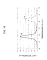
- Fig. 16 illustrates the measurement result representing the relationship between the amount of light of the vertically polarized light Lx and the horizontally polarized light Ly transmitted through the anisotropic prism sheet and the emission angle.
- the unit (a.u.) of the vertical axis stands for "arbitrary unit” and is a relative value.
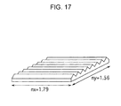
- the index of refraction nx in the prism extension direction of the obtained anisotropic prism sheet is 1.79
- the index of refraction ny in the prism alignment direction is 1.56, and ⁇ n is 0.23.
- the backlight unit is an edge light type including a light source 50, a reflector 51, and a light-guiding plate 52.
- a diffuser 53, a luminance-improvement film 54, an anisotropic prism sheet 45, and a polarizer 55 are stacked on the light-guiding plate 52 in the respective order.
- the front luminance and the illuminance was measured using a luminance colorimeter (E2-contrastXL88 manufactured by ELDIM).
- An isotropic prism sheet (for example, BEF (trademark) manufactured by 3M Company) was used as the luminance-improvement film 54, and the prism extension direction was disposed in the left and right direction in the drawing (horizontal direction).
- the anisotropic prism sheet 45 was disposed with the prism extension direction in the up and down direction in the drawing (vertical direction), and the prism extension direction was disposed orthogonal to the luminance-improvement film 54.
- Two polarizers 55 were provided: one having a light-transmission axis A in the vertical direction: and the other having a light-transmission axis B in the horizontal direction. Both polarizers 55 were used to measure the luminance alignment of the vertically polarized light and the horizontally polarized light.
- the same method was applied to measure the front luminance and the illuminance as that of the second example, except that, instead of the anisotropic prism sheet 45, a unstretched anisotropic prism sheet (90 degrees prism apex angle and 50 ⁇ m pitch) was used.
- both the front luminance and the illuminance of the vertically polarized light of the anisotropic prism sheet according to this example were decreased compared with the anisotropic prism sheet according to the second comparative example.
- the luminance and the illuminance of the horizontally polarized light were increased compared with the anisotropic prism sheet according to the second comparative example.
- the anisotropic prism sheet since a larger amount of vertically polarized light is reflected at the prism surface and is recycled as light in all directions by the diffuser and the reflector, it contributes to an increase in the luminance and illuminance of the horizontally polarized light. Therefore, by setting the transmission axis of the polarizer 55 in the direction of the horizontally polarized light, i.e., the prism alignment direction of the anisotropic prism sheet 45, light can be efficiently used and the front luminance and the illuminance (light extraction efficiency) can be improved.
- the angle formed by the prism sheet and the transmission axis of polarizer (the polarizer disposed on the light incident side of the liquid crystal display panel.
- this is the same
- the polarization of the light emitted from the prism sheet is biased, and it is preferable to match the transmission axis of the polarizer to a direction corresponding to the bias.
- the present invention can be employed even when the transmission axis of the polarizer cannot be matched because of reasons such as improving the contrast of the liquid crystal display apparatus or suppressing moire.
- front luminance of a liquid crystal display apparatus was measured at an angle formed by the prism alignment direction and the direction of the light-transmission axis of the polarizer when a prism sheet, such as that according to the second example, having a greater index of refraction in the prism extension direction than the index of refraction in the prism alignment direction was used for the liquid crystal display apparatus.
- the same method was applied to measure the front luminance and the illuminance as that of the third example, except that, instead of the anisotropic prism sheet, a non-stretched anisotropic prism sheet (90 degrees prism apex angle and 50 ⁇ m pitch) was used.
- the measurement results are shown in Fig. 19 .
- the angle formed by the prism alignment direction of the prism sheet and the direction of the light-transmission axis of the polarizer is from 0° to 45°, the front luminance can be increased compared with an anisotropic prism sheet, and it is more preferable when the angle be from 0° to 20°.
- the index of refraction in the prism extension direction is greater than the index of refraction in the prism alignment direction
- the angle formed by the prism extension direction and the direction of the light-transmission axis of the polarizer is from 0° to 45°, the front luminance can be increased compared with an anisotropic prism sheet, and it is more preferable when the angle be from 0° to 20°.
Landscapes
- Physics & Mathematics (AREA)
- General Physics & Mathematics (AREA)
- Optics & Photonics (AREA)
- Nonlinear Science (AREA)
- Mathematical Physics (AREA)
- Chemical & Material Sciences (AREA)
- Crystallography & Structural Chemistry (AREA)
- Liquid Crystal (AREA)
- Optical Elements Other Than Lenses (AREA)
- Polarising Elements (AREA)
- Planar Illumination Modules (AREA)
- Devices For Indicating Variable Information By Combining Individual Elements (AREA)
Applications Claiming Priority (4)
| Application Number | Priority Date | Filing Date | Title |
|---|---|---|---|
| JP2005267816 | 2005-09-15 | ||
| JP2006079202 | 2006-03-22 | ||
| JP2006243138A JP4158824B2 (ja) | 2005-09-15 | 2006-09-07 | 光透過フィルム、光透過フィルムの製造方法及び液晶表示装置 |
| PCT/JP2006/318276 WO2007032440A1 (fr) | 2005-09-15 | 2006-09-14 | Film de transmission de la lumière, son procédé de fabrication et affichage à cristaux liquides |
Publications (2)
| Publication Number | Publication Date |
|---|---|
| EP1925953A1 true EP1925953A1 (fr) | 2008-05-28 |
| EP1925953A4 EP1925953A4 (fr) | 2011-10-05 |
Family
ID=37865024
Family Applications (1)
| Application Number | Title | Priority Date | Filing Date |
|---|---|---|---|
| EP06797988A Withdrawn EP1925953A4 (fr) | 2005-09-15 | 2006-09-14 | Film de transmission de la lumière, son procédé de fabrication et affichage à cristaux liquides |
Country Status (7)
| Country | Link |
|---|---|
| US (2) | US7712908B2 (fr) |
| EP (1) | EP1925953A4 (fr) |
| JP (1) | JP4158824B2 (fr) |
| KR (1) | KR100949226B1 (fr) |
| CN (1) | CN101091129B (fr) |
| TW (1) | TW200726995A (fr) |
| WO (1) | WO2007032440A1 (fr) |
Families Citing this family (62)
| Publication number | Priority date | Publication date | Assignee | Title |
|---|---|---|---|---|
| KR20080072197A (ko) * | 2007-02-01 | 2008-08-06 | 삼성전자주식회사 | 휘도 특성이 개선된 편광 도광판 및 이의 제작 방법 |
| JP4910842B2 (ja) * | 2007-04-02 | 2012-04-04 | ソニー株式会社 | 光学シートおよび表示装置 |
| JP4626633B2 (ja) * | 2007-08-07 | 2011-02-09 | ソニー株式会社 | 照明装置および液晶表示装置 |
| JP2009059498A (ja) * | 2007-08-30 | 2009-03-19 | Sony Corp | 照明装置および液晶表示装置 |
| JP4991486B2 (ja) | 2007-10-31 | 2012-08-01 | ソニー株式会社 | 光学シートおよびその製造方法ならびに表示装置 |
| JP4902516B2 (ja) | 2007-12-17 | 2012-03-21 | 日東電工株式会社 | 視角制御システムならびに画像表示装置 |
| JP2009157276A (ja) * | 2007-12-27 | 2009-07-16 | Casio Comput Co Ltd | 液晶表示装置 |
| CN101971083A (zh) * | 2008-02-15 | 2011-02-09 | 夏普株式会社 | 液晶显示装置 |
| KR101462161B1 (ko) * | 2008-04-11 | 2014-11-14 | 삼성디스플레이 주식회사 | 복합 편광 시트와 이를 포함하는 액정 표시 장치 |
| JP2011169923A (ja) * | 2008-06-10 | 2011-09-01 | Nippon Shokubai Co Ltd | 光学シートの製造方法、および当該光学シートを含む光源ユニット、表示装置。 |
| JP5217747B2 (ja) * | 2008-08-04 | 2013-06-19 | ソニー株式会社 | 光学フィルムおよびその製造方法ならびに表示装置 |
| US8169386B2 (en) * | 2008-08-19 | 2012-05-01 | Samsung Mobile Display Co., Ltd. | Organic light emitting diode display |
| JP4900363B2 (ja) | 2008-10-28 | 2012-03-21 | カシオ計算機株式会社 | 液晶表示装置 |
| JP4905438B2 (ja) * | 2008-11-18 | 2012-03-28 | カシオ計算機株式会社 | 液晶表示装置 |
| JP2010123464A (ja) * | 2008-11-20 | 2010-06-03 | Hitachi Displays Ltd | 照明装置、光学シート及び液晶表示装置 |
| JP5353385B2 (ja) | 2009-04-02 | 2013-11-27 | ソニー株式会社 | 光学シートの製造方法 |
| JP5437886B2 (ja) | 2009-04-06 | 2014-03-12 | 日東電工株式会社 | 液晶表示装置および集光素子付偏光板 |
| JP5796929B2 (ja) * | 2009-09-16 | 2015-10-21 | 凸版印刷株式会社 | ディスプレイ装置 |
| JP5458772B2 (ja) * | 2009-09-24 | 2014-04-02 | 凸版印刷株式会社 | 偏光解消シート、バックライトユニット及びディスプレイ装置 |
| CN103392134B (zh) * | 2011-02-22 | 2016-05-11 | 皇家飞利浦有限公司 | 包括棱柱形层堆叠的准直器以及包括这种准直器的照明单元 |
| TW201321852A (zh) * | 2011-11-25 | 2013-06-01 | Au Optronics Corp | 液晶顯示裝置 |
| JP5292457B2 (ja) * | 2011-12-28 | 2013-09-18 | 日東電工株式会社 | 視角制御システムならびに画像表示装置 |
| JP5812444B2 (ja) * | 2012-04-13 | 2015-11-11 | 日東電工株式会社 | 光学部材、偏光板のセットおよび液晶表示装置 |
| US8879139B2 (en) | 2012-04-24 | 2014-11-04 | Gentex Corporation | Display mirror assembly |
| JP2014044258A (ja) * | 2012-08-24 | 2014-03-13 | Dainippon Printing Co Ltd | 表示装置 |
| JP2014224963A (ja) * | 2012-09-13 | 2014-12-04 | 日東電工株式会社 | 光学部材、偏光板のセットおよび液晶表示装置 |
| CA2891391A1 (fr) * | 2012-11-16 | 2014-05-22 | Koninklijke Philips N.V. | Afficheur autostereoscopique reflexif ou transflectif a effets de traine reduits |
| JP2016534915A (ja) | 2013-09-24 | 2016-11-10 | ジェンテックス コーポレイション | 表示ミラーアセンブリ |
| CN103594537B (zh) * | 2013-11-07 | 2017-02-08 | 南京兰埔成新材料有限公司 | 一种聚酯太阳能电池背板膜及其制备方法 |
| US9511715B2 (en) | 2014-01-31 | 2016-12-06 | Gentex Corporation | Backlighting assembly for display for reducing cross-hatching |
| EP3119643B1 (fr) | 2014-03-21 | 2018-05-23 | Gentex Corporation | Ensemble miroir d'affichage trimodal |
| EP3126195B1 (fr) | 2014-04-01 | 2019-06-05 | Gentex Corporation | Ensemble miroir d'affichage automatique |
| WO2015199295A1 (fr) * | 2014-06-26 | 2015-12-30 | 서울과학기술대학교 산학협력단 | Dispositif d'affichage |
| KR101597907B1 (ko) * | 2014-11-17 | 2016-02-25 | 서울과학기술대학교 산학협력단 | 디스플레이 장치 |
| WO2016044746A1 (fr) | 2014-09-19 | 2016-03-24 | Gentex Corporation | Ensemble rétroviseur |
| US9694752B2 (en) | 2014-11-07 | 2017-07-04 | Gentex Corporation | Full display mirror actuator |
| KR101977685B1 (ko) | 2014-11-13 | 2019-05-13 | 젠텍스 코포레이션 | 디스플레이를 갖춘 후방 미러 시스템 |
| CN107107825B (zh) | 2014-12-03 | 2020-08-21 | 金泰克斯公司 | 用于车辆的显示镜组件 |
| USD746744S1 (en) | 2014-12-05 | 2016-01-05 | Gentex Corporation | Rearview device |
| US9744907B2 (en) | 2014-12-29 | 2017-08-29 | Gentex Corporation | Vehicle vision system having adjustable displayed field of view |
| US9720278B2 (en) * | 2015-01-22 | 2017-08-01 | Gentex Corporation | Low cost optical film stack |
| JP2018513810A (ja) | 2015-04-20 | 2018-05-31 | ジェンテックス コーポレイション | 装飾を備えた後方視認アセンブリ |
| US10112540B2 (en) | 2015-05-18 | 2018-10-30 | Gentex Corporation | Full display rearview device |
| KR102135427B1 (ko) | 2015-06-22 | 2020-07-17 | 젠텍스 코포레이션 | 진폭-변조된 광의 깜박임을 보정하기 위해 스트리밍된 비디오 이미지를 처리하는 시스템 및 방법 |
| WO2017057395A1 (fr) * | 2015-09-28 | 2017-04-06 | 日東電工株式会社 | Élément optique, et ensemble de plaques polarisantes et dispositif d'affichage à cristaux liquides utilisant cet élément optique |
| JP6829969B2 (ja) * | 2015-09-28 | 2021-02-17 | 日東電工株式会社 | 光学部材、ならびに、該光学部材を用いた偏光板のセットおよび液晶表示装置 |
| USD797627S1 (en) | 2015-10-30 | 2017-09-19 | Gentex Corporation | Rearview mirror device |
| USD798207S1 (en) | 2015-10-30 | 2017-09-26 | Gentex Corporation | Rearview mirror assembly |
| EP3368374B1 (fr) | 2015-10-30 | 2023-12-27 | Gentex Corporation | Manette à bascule |
| US9994156B2 (en) | 2015-10-30 | 2018-06-12 | Gentex Corporation | Rearview device |
| USD800618S1 (en) | 2015-11-02 | 2017-10-24 | Gentex Corporation | Toggle paddle for a rear view device |
| DE102016100063B4 (de) * | 2016-01-04 | 2020-07-09 | Osram Opto Semiconductors Gmbh | Optoelektronische leuchtvorrichtung und anzeigeeinrichtung |
| USD845851S1 (en) | 2016-03-31 | 2019-04-16 | Gentex Corporation | Rearview device |
| USD817238S1 (en) | 2016-04-29 | 2018-05-08 | Gentex Corporation | Rearview device |
| US10025138B2 (en) | 2016-06-06 | 2018-07-17 | Gentex Corporation | Illuminating display with light gathering structure |
| USD809984S1 (en) | 2016-12-07 | 2018-02-13 | Gentex Corporation | Rearview assembly |
| USD854473S1 (en) | 2016-12-16 | 2019-07-23 | Gentex Corporation | Rearview assembly |
| WO2018125898A1 (fr) | 2016-12-30 | 2018-07-05 | Gentex Corporation | Miroir à affichage complet avec vue d'observateur à la demande |
| EP3595931A1 (fr) | 2017-03-17 | 2020-01-22 | Gentex Corporation | Système de caméra arrière à double affichage |
| CN112781010A (zh) * | 2019-11-05 | 2021-05-11 | 余姚煜昌电器有限公司 | 透光单元、工作灯以及应用 |
| CN113299208A (zh) * | 2020-02-21 | 2021-08-24 | 上海睿光新材料科技有限公司 | 无限柔性镜 |
| JP7766227B2 (ja) | 2021-08-20 | 2025-11-10 | ジェンテックス コーポレイション | 照明アセンブリ及び照明アセンブリを有する照射システム |
Family Cites Families (31)
| Publication number | Priority date | Publication date | Assignee | Title |
|---|---|---|---|---|
| US6002829A (en) * | 1992-03-23 | 1999-12-14 | Minnesota Mining And Manufacturing Company | Luminaire device |
| US5828488A (en) * | 1993-12-21 | 1998-10-27 | Minnesota Mining And Manufacturing Co. | Reflective polarizer display |
| US6025897A (en) * | 1993-12-21 | 2000-02-15 | 3M Innovative Properties Co. | Display with reflective polarizer and randomizing cavity |
| CN1052795C (zh) * | 1993-12-21 | 2000-05-24 | 美国3M公司 | 光学显示器 |
| US6804058B1 (en) * | 1993-12-21 | 2004-10-12 | 3M Innovative Properties Company | Electroluminescent light source and display incorporating same |
| AUPM482194A0 (en) | 1994-03-31 | 1994-04-28 | Commonwealth Scientific And Industrial Research Organisation | Birefringent polariser |
| JPH08166582A (ja) | 1994-12-14 | 1996-06-25 | Sharp Corp | 液晶表示装置 |
| AU708412B2 (en) * | 1995-06-26 | 1999-08-05 | Minnesota Mining And Manufacturing Company | Diffusely reflecting multilayer polarizers and mirrors |
| DE69721505T2 (de) * | 1996-02-29 | 2003-11-20 | Minnesota Mining And Manufacturing Company, St. Paul | Film zur helligkeitserhoehung |
| US5808794A (en) * | 1996-07-31 | 1998-09-15 | Weber; Michael F. | Reflective polarizers having extended red band edge for controlled off axis color |
| WO1998012593A1 (fr) * | 1996-09-23 | 1998-03-26 | Philips Electronics N.V. | Systeme d'eclairement pour dispositif d'affichage graphique a panneau plat |
| JP3808992B2 (ja) * | 1997-11-21 | 2006-08-16 | 三菱電機株式会社 | 液晶パネルモジュール |
| US6515785B1 (en) * | 1999-04-22 | 2003-02-04 | 3M Innovative Properties Company | Optical devices using reflecting polarizing materials |
| JP4673463B2 (ja) * | 1999-12-03 | 2011-04-20 | 大日本印刷株式会社 | 液晶表示装置 |
| WO2001053745A1 (fr) * | 2000-01-19 | 2001-07-26 | Omlidon Technologies Llc | Dispositif de polarisation |
| JP3719374B2 (ja) * | 2000-07-14 | 2005-11-24 | シャープ株式会社 | 偏光素子の製造方法 |
| JP2002182039A (ja) | 2000-12-14 | 2002-06-26 | Mitsubishi Rayon Co Ltd | 光源装置用導光体及びこれを用いたフロントライト |
| EP1432948B1 (fr) * | 2001-09-26 | 2009-11-11 | Koninklijke Philips Electronics N.V. | Systeme d'eclairage microstructure permettant de produire de la lumiere polarisee |
| JP2004198725A (ja) | 2002-12-18 | 2004-07-15 | Sumitomo Rubber Ind Ltd | 液晶表示装置、直下型バックライト、及び拡散板 |
| JP2004198958A (ja) | 2002-12-20 | 2004-07-15 | Casio Comput Co Ltd | 偏光素子 |
| JP2004279506A (ja) | 2003-03-13 | 2004-10-07 | Ricoh Co Ltd | 偏光回折素子、偏光回折素子の製造方法、光ピックアップ装置及び光ディスク装置 |
| US6846089B2 (en) * | 2003-05-16 | 2005-01-25 | 3M Innovative Properties Company | Method for stacking surface structured optical films |
| US20040234724A1 (en) * | 2003-05-22 | 2004-11-25 | Eastman Kodak Company | Immisible polymer filled optical elements |
| JP2005017355A (ja) | 2003-06-23 | 2005-01-20 | Fuji Photo Film Co Ltd | 偏光板および液晶表示装置 |
| KR20050068874A (ko) | 2003-12-30 | 2005-07-05 | 엘지.필립스 엘시디 주식회사 | 액정표시장치 |
| JP4179253B2 (ja) | 2004-09-10 | 2008-11-12 | ソニー株式会社 | 偏光素子、液晶表示パネルおよび液晶表示装置 |
| US20060204720A1 (en) * | 2004-12-23 | 2006-09-14 | Biernath Rolf W | Uniaxially oriented birefringent article having a structured surface |
| US20060141218A1 (en) * | 2004-12-23 | 2006-06-29 | Biernath Rolf W | Uniaxially oriented articles having structured surface |
| US20060141220A1 (en) * | 2004-12-23 | 2006-06-29 | Merrill William W | Uniaxially oriented article having a structured surface |
| US20060138702A1 (en) * | 2004-12-23 | 2006-06-29 | Biernath Rolf W | Method of making uniaxially oriented articles having structured surfaces |
| JP2008537793A (ja) * | 2005-04-08 | 2008-09-25 | スリーエム イノベイティブ プロパティズ カンパニー | 表示に使用される構造化配向フィルム |
-
2006
- 2006-09-07 JP JP2006243138A patent/JP4158824B2/ja not_active Expired - Fee Related
- 2006-09-11 TW TW095133506A patent/TW200726995A/zh not_active IP Right Cessation
- 2006-09-14 KR KR1020077010681A patent/KR100949226B1/ko not_active Expired - Fee Related
- 2006-09-14 EP EP06797988A patent/EP1925953A4/fr not_active Withdrawn
- 2006-09-14 CN CN2006800015551A patent/CN101091129B/zh not_active Expired - Fee Related
- 2006-09-14 WO PCT/JP2006/318276 patent/WO2007032440A1/fr not_active Ceased
- 2006-09-14 US US11/718,964 patent/US7712908B2/en active Active
-
2010
- 2010-04-05 US US12/754,270 patent/US7918571B2/en not_active Expired - Fee Related
Also Published As
| Publication number | Publication date |
|---|---|
| WO2007032440A1 (fr) | 2007-03-22 |
| TW200726995A (en) | 2007-07-16 |
| US20100188608A1 (en) | 2010-07-29 |
| KR100949226B1 (ko) | 2010-03-24 |
| KR20080055743A (ko) | 2008-06-19 |
| CN101091129A (zh) | 2007-12-19 |
| EP1925953A4 (fr) | 2011-10-05 |
| TWI323790B (fr) | 2010-04-21 |
| JP4158824B2 (ja) | 2008-10-01 |
| US7918571B2 (en) | 2011-04-05 |
| CN101091129B (zh) | 2012-06-20 |
| US7712908B2 (en) | 2010-05-11 |
| JP2007286573A (ja) | 2007-11-01 |
| US20080247192A1 (en) | 2008-10-09 |
Similar Documents
| Publication | Publication Date | Title |
|---|---|---|
| US7918571B2 (en) | Light-transmitting film, method of forming light-transmitting film, and liquid crystal display | |
| CN101542366B (zh) | 显示装置 | |
| TWI566009B (zh) | Liquid crystal display device | |
| US7864267B2 (en) | Optical sheet and display unit | |
| US7995158B2 (en) | Liquid crystal display apparatus | |
| US7880824B2 (en) | Surface emitting device, liquid crystal display, and optical sheet combination | |
| TWI391714B (zh) | 可透射光膜及其製造方法,與顯示裝置 | |
| TW201339704A (zh) | 液晶顯示裝置 | |
| JP2008122991A (ja) | 光透過フィルム、光透過フィルムの製造方法及び液晶表示装置 | |
| JP2011075964A (ja) | 液晶表示装置 |
Legal Events
| Date | Code | Title | Description |
|---|---|---|---|
| PUAI | Public reference made under article 153(3) epc to a published international application that has entered the european phase |
Free format text: ORIGINAL CODE: 0009012 |
|
| 17P | Request for examination filed |
Effective date: 20070515 |
|
| AK | Designated contracting states |
Kind code of ref document: A1 Designated state(s): DE FR GB |
|
| DAX | Request for extension of the european patent (deleted) | ||
| RBV | Designated contracting states (corrected) |
Designated state(s): DE FR GB |
|
| A4 | Supplementary search report drawn up and despatched |
Effective date: 20110907 |
|
| RIC1 | Information provided on ipc code assigned before grant |
Ipc: F21Y 103/00 20060101ALI20110901BHEP Ipc: F21V 5/02 20060101ALI20110901BHEP Ipc: G02B 5/30 20060101AFI20110901BHEP Ipc: G02B 5/04 20060101ALI20110901BHEP Ipc: G02F 1/1335 20060101ALI20110901BHEP |
|
| 17Q | First examination report despatched |
Effective date: 20121105 |
|
| RAP1 | Party data changed (applicant data changed or rights of an application transferred) |
Owner name: SATURN LICENSING LLC |
|
| STAA | Information on the status of an ep patent application or granted ep patent |
Free format text: STATUS: THE APPLICATION IS DEEMED TO BE WITHDRAWN |
|
| 18D | Application deemed to be withdrawn |
Effective date: 20200603 |