EP1925990A2 - Appareil de formation d'image capable de former une image recto-verso sur une seule feuille - Google Patents
Appareil de formation d'image capable de former une image recto-verso sur une seule feuille Download PDFInfo
- Publication number
- EP1925990A2 EP1925990A2 EP07120409A EP07120409A EP1925990A2 EP 1925990 A2 EP1925990 A2 EP 1925990A2 EP 07120409 A EP07120409 A EP 07120409A EP 07120409 A EP07120409 A EP 07120409A EP 1925990 A2 EP1925990 A2 EP 1925990A2
- Authority
- EP
- European Patent Office
- Prior art keywords
- printing medium
- image forming
- feeding
- roller
- forming apparatus
- Prior art date
- Legal status (The legal status is an assumption and is not a legal conclusion. Google has not performed a legal analysis and makes no representation as to the accuracy of the status listed.)
- Granted
Links
Images

Classifications
-
- G—PHYSICS
- G03—PHOTOGRAPHY; CINEMATOGRAPHY; ANALOGOUS TECHNIQUES USING WAVES OTHER THAN OPTICAL WAVES; ELECTROGRAPHY; HOLOGRAPHY
- G03G—ELECTROGRAPHY; ELECTROPHOTOGRAPHY; MAGNETOGRAPHY
- G03G15/00—Apparatus for electrographic processes using a charge pattern
-
- B—PERFORMING OPERATIONS; TRANSPORTING
- B65—CONVEYING; PACKING; STORING; HANDLING THIN OR FILAMENTARY MATERIAL
- B65H—HANDLING THIN OR FILAMENTARY MATERIAL, e.g. SHEETS, WEBS, CABLES
- B65H5/00—Feeding articles separated from piles; Feeding articles to machines
- B65H5/26—Duplicate, alternate, selective, or coacting feeds
-
- B—PERFORMING OPERATIONS; TRANSPORTING
- B65—CONVEYING; PACKING; STORING; HANDLING THIN OR FILAMENTARY MATERIAL
- B65H—HANDLING THIN OR FILAMENTARY MATERIAL, e.g. SHEETS, WEBS, CABLES
- B65H1/00—Supports or magazines for piles from which articles are to be separated
- B65H1/04—Supports or magazines for piles from which articles are to be separated adapted to support articles substantially horizontally, e.g. for separation from top of pile
-
- B—PERFORMING OPERATIONS; TRANSPORTING
- B65—CONVEYING; PACKING; STORING; HANDLING THIN OR FILAMENTARY MATERIAL
- B65H—HANDLING THIN OR FILAMENTARY MATERIAL, e.g. SHEETS, WEBS, CABLES
- B65H3/00—Separating articles from piles
- B65H3/02—Separating articles from piles using friction forces between articles and separator
- B65H3/06—Rollers or like rotary separators
- B65H3/0607—Rollers or like rotary separators cooperating with means for automatically separating the pile from roller or rotary separator after a separation step
-
- B—PERFORMING OPERATIONS; TRANSPORTING
- B65—CONVEYING; PACKING; STORING; HANDLING THIN OR FILAMENTARY MATERIAL
- B65H—HANDLING THIN OR FILAMENTARY MATERIAL, e.g. SHEETS, WEBS, CABLES
- B65H9/00—Registering, e.g. orientating, articles; Devices therefor
- B65H9/002—Registering, e.g. orientating, articles; Devices therefor changing orientation of sheet by only controlling movement of the forwarding means, i.e. without the use of stop or register wall
-
- G—PHYSICS
- G03—PHOTOGRAPHY; CINEMATOGRAPHY; ANALOGOUS TECHNIQUES USING WAVES OTHER THAN OPTICAL WAVES; ELECTROGRAPHY; HOLOGRAPHY
- G03G—ELECTROGRAPHY; ELECTROPHOTOGRAPHY; MAGNETOGRAPHY
- G03G15/00—Apparatus for electrographic processes using a charge pattern
- G03G15/22—Apparatus for electrographic processes using a charge pattern involving the combination of more than one step according to groups G03G13/02 - G03G13/20
- G03G15/23—Apparatus for electrographic processes using a charge pattern involving the combination of more than one step according to groups G03G13/02 - G03G13/20 specially adapted for copying both sides of an original or for copying on both sides of a recording or image-receiving material
- G03G15/231—Arrangements for copying on both sides of a recording or image-receiving material
- G03G15/238—Arrangements for copying on both sides of a recording or image-receiving material using more than one reusable electrographic recording member, e.g. single pass duplex copiers
-
- G—PHYSICS
- G03—PHOTOGRAPHY; CINEMATOGRAPHY; ANALOGOUS TECHNIQUES USING WAVES OTHER THAN OPTICAL WAVES; ELECTROGRAPHY; HOLOGRAPHY
- G03G—ELECTROGRAPHY; ELECTROPHOTOGRAPHY; MAGNETOGRAPHY
- G03G15/00—Apparatus for electrographic processes using a charge pattern
- G03G15/65—Apparatus which relate to the handling of copy material
- G03G15/6502—Supplying of sheet copy material; Cassettes therefor
-
- G—PHYSICS
- G03—PHOTOGRAPHY; CINEMATOGRAPHY; ANALOGOUS TECHNIQUES USING WAVES OTHER THAN OPTICAL WAVES; ELECTROGRAPHY; HOLOGRAPHY
- G03G—ELECTROGRAPHY; ELECTROPHOTOGRAPHY; MAGNETOGRAPHY
- G03G2215/00—Apparatus for electrophotographic processes
- G03G2215/00362—Apparatus for electrophotographic processes relating to the copy medium handling
- G03G2215/00367—The feeding path segment where particular handling of the copy medium occurs, segments being adjacent and non-overlapping. Each segment is identified by the most downstream point in the segment, so that for instance the segment labelled "Fixing device" is referring to the path between the "Transfer device" and the "Fixing device"
- G03G2215/00379—Copy medium holder
- G03G2215/00392—Manual input tray
-
- G—PHYSICS
- G03—PHOTOGRAPHY; CINEMATOGRAPHY; ANALOGOUS TECHNIQUES USING WAVES OTHER THAN OPTICAL WAVES; ELECTROGRAPHY; HOLOGRAPHY
- G03G—ELECTROGRAPHY; ELECTROPHOTOGRAPHY; MAGNETOGRAPHY
- G03G2215/00—Apparatus for electrophotographic processes
- G03G2215/00362—Apparatus for electrophotographic processes relating to the copy medium handling
- G03G2215/00367—The feeding path segment where particular handling of the copy medium occurs, segments being adjacent and non-overlapping. Each segment is identified by the most downstream point in the segment, so that for instance the segment labelled "Fixing device" is referring to the path between the "Transfer device" and the "Fixing device"
- G03G2215/00417—Post-fixing device
- G03G2215/0043—Refeeding path
-
- G—PHYSICS
- G03—PHOTOGRAPHY; CINEMATOGRAPHY; ANALOGOUS TECHNIQUES USING WAVES OTHER THAN OPTICAL WAVES; ELECTROGRAPHY; HOLOGRAPHY
- G03G—ELECTROGRAPHY; ELECTROPHOTOGRAPHY; MAGNETOGRAPHY
- G03G2215/00—Apparatus for electrophotographic processes
- G03G2215/00362—Apparatus for electrophotographic processes relating to the copy medium handling
- G03G2215/00535—Stable handling of copy medium
- G03G2215/00556—Control of copy medium feeding
- G03G2215/00586—Control of copy medium feeding duplex mode
-
- G—PHYSICS
- G03—PHOTOGRAPHY; CINEMATOGRAPHY; ANALOGOUS TECHNIQUES USING WAVES OTHER THAN OPTICAL WAVES; ELECTROGRAPHY; HOLOGRAPHY
- G03G—ELECTROGRAPHY; ELECTROPHOTOGRAPHY; MAGNETOGRAPHY
- G03G2215/00—Apparatus for electrophotographic processes
- G03G2215/01—Apparatus for electrophotographic processes for producing multicoloured copies
- G03G2215/0103—Plural electrographic recording members
- G03G2215/0119—Linear arrangement adjacent plural transfer points
- G03G2215/0138—Linear arrangement adjacent plural transfer points primary transfer to a recording medium carried by a transport belt
- G03G2215/0148—Linear arrangement adjacent plural transfer points primary transfer to a recording medium carried by a transport belt the linear arrangement being slanted
Definitions
- An image forming apparatus prints image data on a printing medium, such as paper, according to a printing signal applied from a host apparatus such as a personal computer (PC).
- the image forming apparatus comprises a supplying part which supplies individual sheets of printing media, an image forming part which forms an image on a printing medium fed from the supplying part by a feeding part, and a discharging part which discharges the image-formed printing medium.
- image forming apparatuses also have been made to comprise a duplex printing function in which images are printed on both sides of the printing medium.
- the feeding roller part comprises: a sub pick-up roller which picks up the printing medium in the sub-feeding part; and a feeding roller which transfers the printing medium transferred to the reversing part and the printing medium picked up by the sub pick-up roller to the image forming part.
- the feeding roller part comprises a second guide member which is provided on one side of the feeding roller and guides the printing medium guided through the first guide member to the feeding roller.
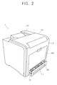
- FIG. 2 is a perspective view illustrating an exterior configuration of an image forming apparatus 1 according to an example embodiment of the present invention
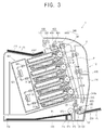
- FIG. 3 is a sectional view illustrating an interior configuration of an image forming apparatus 1 according to an example embodiment of the present invention.
- Such an image forming apparatus can be a printer, a photo-copier, a facsimile machine or a multi-functional product.
- the image forming apparatus 1 comprises a main feeding part 100, a sub-feeding part 200, an image forming part 300, a fusing part 400, a discharging part 500, a reversing part 600, and a main body 700 which supports all the components.
- the main feeding part main body 110 is detachably mounted to the main body 700.
- the main feeding part main body 110 is mounted to the main body 700 and transfers the printing medium P0 to the image forming part 300 according to a receipt of a printing signal. Also, if the supply of the printing medium P0 is exhausted or a jam occurs, the main feeding part main body 110 may be separated from the main body 700 to allow for a loading of a printing medium P0 or to allow for a solution to the jam.
- the main feeding cassette part 120 is provided in a rear area of the main feeding part main body 110 and supplies the stored printing medium P0 to the image forming part 300.
- the main feeding cassette part 120 comprises a knock-up plate 121 on which printing media, including the printing medium P0, are stacked.
- a main pick-up roller 123 separates the printing medium P0 from the stack.
- a registration roller 125 aligns a leading edge of both the picked up printing medium P0 and the printing medium P1.
- the registration roller 125 also supplies the printing medium P0 and the printing medium P1 to the image forming part 300.
- the knock-up plate 121 is biased to move toward the main pick-up roller 123 and enables the printing medium P0 stored on the top of the stack of printing media to contact the main pick-up roller 123 if the main feeding part 100 is mounted to the main body 700.
- the registration roller 125 aligns the leading edge of the printing medium P0, having been separated from the knock-up plate 121, and supplies the printing medium P0 to a transfer belt 341 of the image forming part 300.
- the registration roller 125 may be a center alignment type of registration roller, which aligns the printing medium P0 from a central area of the leading edge of the printing medium P0 to a side area, and a side alignment type of registration roller, which aligns the printing medium P0 from a side area of the leading edge of the printing medium P0. Further description of the configuration of the registration roller 125 will be omitted as it is a known technology.
- the feeding roller part 130 comprises a sub pick-up roller 131, which separates the printing medium P0 stored in the sub-feeding part 200 from other printing media.
- a feeding roller 133 transfers the printing medium P0 separated by the sub pick-up roller 131 and the printing medium P1 on which an image is formed on a first surface thereof and which is transferred from the printing medium reversing part 600 to the registration roller 125.
- a second guide member 135 guides the printing medium P1 transferred from the printing medium reversing part 600 to the feeding roller 133.
- the sub pick-up roller 131 is provided on one side of the feeding inlet 111 and picks up a printing medium at a top portion of the sub-feeding part 200 that is proximate to the inside of the main body 700.
- the description of the sub pick-up roller 131 will be omitted as this feature has the same configuration as that of the main pick-up roller 123.
- the feeding roller 133 feeds the printing medium P0 separated by the sub pick-up roller 131 to the registration roller 125, and changes the feeding direction of the printing medium P1 on which an image is formed on a first surface thereof and which is fed through the reversing part 600 to transfer the printing medium P1 to the registration roller 125.
- a feeding direction of the printing medium P1 is changed toward the image forming part 300 by the feeding roller 133 to allow for the second surface of the printing medium P1 to contact each of the developing devices 310Y, 310M, 310C, and 310K.
- the feeding roller 133 comprises a driving roller 133a which is rotated by a driving part (not shown), and a driven roller 133b which is rotated with the rotation of the driving roller 133a.
- the feeding roller 133 may be provided as a singular roller, or may be provided as a plurality of rollers according to a distance and a path from the sub pick-up roller 131 to the registration roller 125.
- the second guide member 135 is provided on one side of the feeding roller 133 and guides the printing medium P1 to the feeding roller 133.
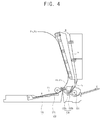
- the feeding roller 133 is provided inside the main feeding part 100 to be detachably mounted to the main body 700 and to be separate from a reversing path 711 (see FIGS. 3 and 4) provided in the main body frame 710.
- the printing medium P1 tends to move in a substantially straight proceeding direction as a result of the rigidity thereof.
- the second guide member 135 guides the printing medium P1, having passed through the reversing path 711 to the feeding roller 133, to enable the feeding direction of the printing medium P1 to be changed in a stable manner.
- the second guide member 135 may have a length and a shape that each correspond to a portion of the space from one end part of the reversing path 711 to the feeding roller 133. Also, the second guide member 135 may be straight or curved. The second guide member 135 may comprise a pair of members to guide both a front surface and a rear surface of the printing medium. The second guide member 135 may be adhered on one side of the feeding roller 133 as a separate member, or may be integrated with the main feeding part main body 110.
- the sub-feeding part 200 is coupled to a casing 750 of the main body 700 to allow the sub feeding part 200 to be pivotally rotated and may store printing media having different sizes or characteristics (i.e., OHP film, photographic paper, scratch paper, or B4 and B5 size paper) than the printing medium P0.
- the sub-feeding part 200 is coupled to the casing 750 of the main body 700 as shown in FIG. 2 if a user does not want to use it.
- the sub-feeding part 200 is pivotally rotated in a predetermined angle with respect to the casing 750 as shown in FIG. 3 to supply the printing medium P0 to the feeding inlet 111 if the user does want to use it.
- the image forming part 300 forms an image on a first surface of the printing medium P0 fed from the main feeding part 100 and the sub-feeding part 200, and forms an image on the second surface of the printing medium P1.
- the image forming part 300 may be an ink jet which forms an image by ejecting ink onto the printing medium, an electrophotographic type which selectively spreads developer on the printing medium P0 or P1 according to a potential difference between a photosensitive body and a developer, and a direct thermal type which applies heat and pressure to an ink ribbon on which ink is coated and transfers the ink to the printing medium P0 or P1 to form an image thereon.
- the image forming part 300 employs a color electrophotographic method.
- the image forming part 300 comprises four developing devices 310Y, 310M, 310C, and 310K that are provided to form yellow, magenta, cyan, and black images to form a full color image in a single pass of the printing medium P0 or P1 through the image forming part 300.
- the plurality of developing devices 310Y, 310M, 310C, and 310K spread developer T of each color onto the printing media P0 and P1.
- An exposure part 320 scans light on the surface of photosensitive bodies 311Y, 311M, 311C, and 311K of each of the developing devices 310Y, 310M, 310C, and 310K, respectively, to form an electrostatic latent image thereon.
- a plurality of transfer rollers 330Y, 330M, 330C, and 330K transfer the developer spread onto the photosensitive bodies 311Y, 311M, 311C, and 311K to the printing media P0 and P1.
- a feeding part 340 sequentially transfers the printing media P0 and P1 to the plurality of developing devices 310Y, 310M, 310C, and 310K.
- the plurality of developing devices 310Y, 310M, 310C, and 310K comprise the photosensitive bodies 311Y, 311M, 311C, and 311K, developer storing parts 317Y, 317M, 317C, and 317K which accommodate developer T therein, developing rollers 313Y, 313M, 313C, and 313K which develop the developer on an electrostatic latent image of the photosensitive bodies 311Y, 311M, 311C, and 311K, supplying rollers 314Y, 314M, 314C, and 314K which supply the developer T for the developing rollers 313Y, 313M, 313C, and 313K, and electrifying rollers 315Y, 315M, 315C, and 315K which electrify the photosensitive bodies 311Y, 311M, 311C, and 311K to a predetermined potential.
- the description of a configuration of the developing devices 310Y, 310M, 310C, and 310K will be
- the exposure part 320 scans a beam onto each of the photosensitive bodies 311Y, 311M, 311C, and 311K provided in each of the developing devices 310Y, 310M, 310C, and 310K to form an electrostatic latent image on each of the bodies.
- the exposure part 320 has a multi-beam light scanning configuration to allow the exposure part 320 to scan the beam to the plurality of photosensitive bodies 311Y, 311M, 311C, and 311K simultaneously.
- the exposure part 320 comprises a light source (not shown), a polygon mirror 321 which cause the beam to be inclined, and an f- ⁇ lens 325 which scans the beam inclined in the polygon mirror 321 onto a surface to be scanned to form an image.
- the feeding part 340 feeds the printing media P0 and P1 to sequentially spread the developer from each of the photosensitive bodies 311Y, 311M, 311C, and 311K to form an image on the printing media P0 and P1.
- the feeding part 340 comprises a transfer belt (PTP) which adsorbs the printing medium whose leading edge is aligned in the registration roller 125 onto a surface thereof by static electricity and rotates, a belt driving roller 343 which drives the rotation of the transfer belt 341, and a belt electrifying roller 345 which electrifies the surface of the transfer belt 341.
- PTP transfer belt
- the description of the configuration of the feeding part 340 will be omitted as it is similar to that of a conventional configuration thereof.
- the fusing part 400 fuses the developer on the surface of the printing medium P1 whose first surface is previously printed on and printing medium P2 whose second surface is previously printed on by applying heat and pressure to the printing media P0, P1, and P2.
- the fusing part 400 comprises a heating roller 410 and a pressing roller 420 which apply heat and pressure, respectively, to the printing media P0, P1 and P2.
- the discharging part 500 discharges the image-formed printing media P0, P1 and P2 through the fusing process in the fusing part 400 to a storing part 753 of the casing 750.
- the discharging part 500 comprises a discharging roller 510 which discharges the printing media P0, P1 and P2, and a reverse roller 520 which changes a feeding direction of the printing medium P1 according to a user's duplex printing signal and transfers the printing medium P1 to the printing medium reversing part 600.
- the discharging part 500 may further comprise a reversing lever (not shown) which guides the printing medium P1 to the printing medium reversing part 600.
- the reversing part 600 transfers the printing medium P1 from the reverse roller 520 and toward the feeding roller 133 of the main feeding part 100.
- the reversing part 600 comprises a reversing roller 610 provided along the reversing path 711 formed in the main body frame 710.
- the reversing roller 610 may comprise a plurality of rollers according to the length and the path of the reversing path 711.
- the reversing part 600 also comprises a first guide member 620 which stably guides the printing medium P1 transferred through the paper reversing path 711 to the feeding roller 133 in an outlet area of the reversing path 711.
- the first guide member 620 may comprise a pair of members on opposite sides of the reversing path 711.
- the main body 700 comprises a main body frame 710 supporting the above-described components, and a main body casing 750 to protect the main body frame 710 and the components from an external impact.
- the main body frame 710 includes the reversing path 711 to guide the printing medium P1 to be transferred to the feeding roller 133 of the main feeding part 100.
- the reversing path 711 may have a length corresponding to the height of the plurality of developing devices 310Y, 310M, 310C, and 310K.
- the printing medium P0 stored in the sub-feeding part 200 enters, by the rotation of the sub pick-up roller 131, the inside of the main body 700 through the feeding inlet 111.
- the printing medium P0 is then guided through the feeding roller 133 to the registration roller 125, and passes through the image forming part 300 to have an image-formed thereon.
- a feeding roller which has been provided separately in a conventional duplex printing part is, according to an aspect of the present invention, provided in the inside of a main feeding part to thereby minimize the height of the duplex printing part. Also, the number of the feeding rollers provided in the duplex printing part and the main feeding part may be reduced to lower production costs.
Landscapes
- Physics & Mathematics (AREA)
- General Physics & Mathematics (AREA)
- Engineering & Computer Science (AREA)
- Mechanical Engineering (AREA)
- Sheets, Magazines, And Separation Thereof (AREA)
- Conveyance By Endless Belt Conveyors (AREA)
- Registering Or Overturning Sheets (AREA)
- Paper Feeding For Electrophotography (AREA)
Priority Applications (1)
| Application Number | Priority Date | Filing Date | Title |
|---|---|---|---|
| EP12151727.0A EP2444856A3 (fr) | 2006-11-21 | 2007-11-09 | Appareil de formation d'image capable de former une image recto-verso sur une seule feuille |
Applications Claiming Priority (1)
| Application Number | Priority Date | Filing Date | Title |
|---|---|---|---|
| KR1020060115506A KR101135892B1 (ko) | 2006-11-21 | 2006-11-21 | 양면인쇄 가능한 화상형성장치 |
Related Child Applications (2)
| Application Number | Title | Priority Date | Filing Date |
|---|---|---|---|
| EP12151727.0A Division EP2444856A3 (fr) | 2006-11-21 | 2007-11-09 | Appareil de formation d'image capable de former une image recto-verso sur une seule feuille |
| EP12151727.0A Division-Into EP2444856A3 (fr) | 2006-11-21 | 2007-11-09 | Appareil de formation d'image capable de former une image recto-verso sur une seule feuille |
Publications (3)
| Publication Number | Publication Date |
|---|---|
| EP1925990A2 true EP1925990A2 (fr) | 2008-05-28 |
| EP1925990A3 EP1925990A3 (fr) | 2009-06-24 |
| EP1925990B1 EP1925990B1 (fr) | 2020-01-01 |
Family
ID=38950311
Family Applications (2)
| Application Number | Title | Priority Date | Filing Date |
|---|---|---|---|
| EP12151727.0A Withdrawn EP2444856A3 (fr) | 2006-11-21 | 2007-11-09 | Appareil de formation d'image capable de former une image recto-verso sur une seule feuille |
| EP07120409.3A Not-in-force EP1925990B1 (fr) | 2006-11-21 | 2007-11-09 | Appareil de formation d'image capable de former une image recto-verso sur une seule feuille |
Family Applications Before (1)
| Application Number | Title | Priority Date | Filing Date |
|---|---|---|---|
| EP12151727.0A Withdrawn EP2444856A3 (fr) | 2006-11-21 | 2007-11-09 | Appareil de formation d'image capable de former une image recto-verso sur une seule feuille |
Country Status (4)
| Country | Link |
|---|---|
| US (2) | US8718532B2 (fr) |
| EP (2) | EP2444856A3 (fr) |
| KR (1) | KR101135892B1 (fr) |
| CN (1) | CN101187794A (fr) |
Families Citing this family (1)
| Publication number | Priority date | Publication date | Assignee | Title |
|---|---|---|---|---|
| KR101172398B1 (ko) * | 2007-08-03 | 2012-08-08 | 삼성전자주식회사 | 인쇄매체 공급장치 및 이를 포함하는 화상형성장치 |
Citations (3)
| Publication number | Priority date | Publication date | Assignee | Title |
|---|---|---|---|---|
| JP2002328500A (ja) | 2001-05-01 | 2002-11-15 | Canon Inc | 画像形成装置 |
| JP2006232440A (ja) | 2005-02-23 | 2006-09-07 | Fuji Xerox Co Ltd | 画像形成装置 |
| US20060291931A1 (en) | 2005-06-24 | 2006-12-28 | Fuji Xerox Co., Ltd. | Image formation device |
Family Cites Families (22)
| Publication number | Priority date | Publication date | Assignee | Title |
|---|---|---|---|---|
| JP3102001B2 (ja) * | 1989-03-03 | 2000-10-23 | 富士ゼロックス株式会社 | 画像形成装置および画像形成装置の給紙ユニット |
| JP2692957B2 (ja) * | 1989-06-12 | 1997-12-17 | キヤノン株式会社 | 再給紙搬送路を有する画像形成装置 |
| JPH03235968A (ja) | 1990-02-13 | 1991-10-21 | Canon Inc | 画像形成装置 |
| JP3389688B2 (ja) * | 1993-11-12 | 2003-03-24 | 富士ゼロックス株式会社 | 画像形成装置の給紙装置 |
| JPH07325437A (ja) | 1994-05-30 | 1995-12-12 | Fuji Xerox Co Ltd | 画像形成装置の給紙装置 |
| JP3235968B2 (ja) | 1996-10-14 | 2001-12-04 | ダイセル化学工業株式会社 | 三成分系生分解性樹脂組成物 |
| KR100251953B1 (ko) | 1997-11-03 | 2000-04-15 | 윤종용 | 양면인쇄장치의 용지 반전 장치 |
| JP2001235905A (ja) | 2000-02-22 | 2001-08-31 | Minolta Co Ltd | 画像形成装置 |
| JP2003201045A (ja) * | 2002-01-10 | 2003-07-15 | Oki Data Corp | 給紙装置 |
| KR100547130B1 (ko) * | 2003-07-04 | 2006-01-26 | 삼성전자주식회사 | 전자사진방식 인쇄기 |
| US7292820B2 (en) * | 2003-07-30 | 2007-11-06 | Lexmark International, Inc. | Integrated media input tray including electronics |
| US7761046B2 (en) * | 2003-10-02 | 2010-07-20 | Sharp Kabushiki Kaisha | Hybrid paper supply module and image forming apparatus equipped with such hybrid paper supply module, and also paper supply mechanism and image forming apparatus equipped with such paper supply mechanism |
| JP2005112605A (ja) | 2003-10-10 | 2005-04-28 | Murata Mach Ltd | 反転搬送装置 |
| JP4323938B2 (ja) | 2003-12-10 | 2009-09-02 | キヤノン株式会社 | 画像形成装置 |
| US7162182B2 (en) * | 2004-03-19 | 2007-01-09 | Lexmark International, Inc. | Image forming device having a door assembly and method of use |
| JP4513682B2 (ja) * | 2005-07-25 | 2010-07-28 | 富士ゼロックス株式会社 | 給紙装置及びそれを備えた画像形成装置 |
| US7382998B2 (en) * | 2005-08-25 | 2008-06-03 | Lexmark International, Inc. | Robust door panel breakaway mechanism for an image forming device |
| JP4664827B2 (ja) * | 2006-01-26 | 2011-04-06 | 株式会社リコー | 搬送装置および画像形成装置 |
| US7675536B2 (en) * | 2006-04-19 | 2010-03-09 | Lexmark International, Inc. | Architectures for multi-functional image forming devices |
| US7639965B2 (en) * | 2006-04-19 | 2009-12-29 | Lexmark International, Inc. | Architecture for an image-forming device |
| JP4697880B2 (ja) * | 2006-05-11 | 2011-06-08 | 株式会社リコー | 手差し給紙装置及びその手差し給紙装置を有する画像形成装置 |
| KR200432616Y1 (ko) | 2006-08-07 | 2006-12-05 | 김기연 | 자전거 스탠드 |
-
2006
- 2006-11-21 KR KR1020060115506A patent/KR101135892B1/ko not_active Expired - Fee Related
-
2007
- 2007-11-09 EP EP12151727.0A patent/EP2444856A3/fr not_active Withdrawn
- 2007-11-09 EP EP07120409.3A patent/EP1925990B1/fr not_active Not-in-force
- 2007-11-16 US US11/941,255 patent/US8718532B2/en active Active
- 2007-11-21 CN CNA2007101880028A patent/CN101187794A/zh active Pending
-
2014
- 2014-03-19 US US14/219,510 patent/US20140291916A1/en not_active Abandoned
Patent Citations (3)
| Publication number | Priority date | Publication date | Assignee | Title |
|---|---|---|---|---|
| JP2002328500A (ja) | 2001-05-01 | 2002-11-15 | Canon Inc | 画像形成装置 |
| JP2006232440A (ja) | 2005-02-23 | 2006-09-07 | Fuji Xerox Co Ltd | 画像形成装置 |
| US20060291931A1 (en) | 2005-06-24 | 2006-12-28 | Fuji Xerox Co., Ltd. | Image formation device |
Also Published As
| Publication number | Publication date |
|---|---|
| US20080118293A1 (en) | 2008-05-22 |
| EP2444856A3 (fr) | 2016-05-25 |
| CN101187794A (zh) | 2008-05-28 |
| US20140291916A1 (en) | 2014-10-02 |
| EP1925990B1 (fr) | 2020-01-01 |
| EP1925990A3 (fr) | 2009-06-24 |
| US8718532B2 (en) | 2014-05-06 |
| KR20080046058A (ko) | 2008-05-26 |
| EP2444856A2 (fr) | 2012-04-25 |
| KR101135892B1 (ko) | 2012-07-04 |
Similar Documents
| Publication | Publication Date | Title |
|---|---|---|
| EP1826626B1 (fr) | Appareils de formation d'images en couleur, formation d'images en couleur en tandem et formation d'images | |
| US8554124B2 (en) | Printing medium feeding apparatus and image forming apparatus having the same | |
| US11866287B2 (en) | Sheet feeding device and an image forming apparatus with a sheet feeding device | |
| US7796936B2 (en) | Image forming device with multimode duplexer | |
| US9285750B2 (en) | Image forming apparatus | |
| EP1925990B1 (fr) | Appareil de formation d'image capable de former une image recto-verso sur une seule feuille | |
| US11886136B2 (en) | Image forming apparatus including regulating portion configured to contact sheet that is conveyed on conveyance surface of belt | |
| JP5564876B2 (ja) | 記録媒体供給装置及び画像形成装置 | |
| JP4513682B2 (ja) | 給紙装置及びそれを備えた画像形成装置 | |
| US20060219114A1 (en) | Sheet transport mechanism for image forming device | |
| JP2009292602A (ja) | 画像形成装置 | |
| JP2025043976A (ja) | 画像形成システム | |
| CN117142190A (zh) | 片材进给设备和成像设备 | |
| JP2006264792A (ja) | 整列手段および画像形成装置 | |
| JP2006273498A (ja) | 画像形成装置 | |
| JP2000007191A (ja) | 画像形成装置 |
Legal Events
| Date | Code | Title | Description |
|---|---|---|---|
| PUAI | Public reference made under article 153(3) epc to a published international application that has entered the european phase |
Free format text: ORIGINAL CODE: 0009012 |
|
| AK | Designated contracting states |
Kind code of ref document: A2 Designated state(s): AT BE BG CH CY CZ DE DK EE ES FI FR GB GR HU IE IS IT LI LT LU LV MC MT NL PL PT RO SE SI SK TR |
|
| AX | Request for extension of the european patent |
Extension state: AL BA HR MK RS |
|
| PUAL | Search report despatched |
Free format text: ORIGINAL CODE: 0009013 |
|
| AK | Designated contracting states |
Kind code of ref document: A3 Designated state(s): AT BE BG CH CY CZ DE DK EE ES FI FR GB GR HU IE IS IT LI LT LU LV MC MT NL PL PT RO SE SI SK TR |
|
| AX | Request for extension of the european patent |
Extension state: AL BA HR MK RS |
|
| 17P | Request for examination filed |
Effective date: 20091224 |
|
| 17Q | First examination report despatched |
Effective date: 20100129 |
|
| AKX | Designation fees paid |
Designated state(s): DE FR GB NL |
|
| RAP1 | Party data changed (applicant data changed or rights of an application transferred) |
Owner name: SAMSUNG ELECTRONICS CO., LTD. |
|
| RAP1 | Party data changed (applicant data changed or rights of an application transferred) |
Owner name: S-PRINTING SOLUTION CO., LTD. |
|
| STAA | Information on the status of an ep patent application or granted ep patent |
Free format text: STATUS: EXAMINATION IS IN PROGRESS |
|
| RAP1 | Party data changed (applicant data changed or rights of an application transferred) |
Owner name: HP PRINTING KOREA CO., LTD. |
|
| GRAJ | Information related to disapproval of communication of intention to grant by the applicant or resumption of examination proceedings by the epo deleted |
Free format text: ORIGINAL CODE: EPIDOSDIGR1 |
|
| GRAP | Despatch of communication of intention to grant a patent |
Free format text: ORIGINAL CODE: EPIDOSNIGR1 |
|
| GRAP | Despatch of communication of intention to grant a patent |
Free format text: ORIGINAL CODE: EPIDOSNIGR1 |
|
| STAA | Information on the status of an ep patent application or granted ep patent |
Free format text: STATUS: GRANT OF PATENT IS INTENDED |
|
| INTG | Intention to grant announced |
Effective date: 20190830 |
|
| RIN1 | Information on inventor provided before grant (corrected) |
Inventor name: KIM, JAE-YONG Inventor name: KIM, KI-HUN Inventor name: LEE, JIN-SOO |
|
| GRAS | Grant fee paid |
Free format text: ORIGINAL CODE: EPIDOSNIGR3 |
|
| GRAA | (expected) grant |
Free format text: ORIGINAL CODE: 0009210 |
|
| STAA | Information on the status of an ep patent application or granted ep patent |
Free format text: STATUS: THE PATENT HAS BEEN GRANTED |
|
| RAP1 | Party data changed (applicant data changed or rights of an application transferred) |
Owner name: HEWLETT-PACKARD DEVELOPMENT COMPANY, L.P. |
|
| AK | Designated contracting states |
Kind code of ref document: B1 Designated state(s): DE FR GB NL |
|
| REG | Reference to a national code |
Ref country code: GB Ref legal event code: FG4D |
|
| REG | Reference to a national code |
Ref country code: DE Ref legal event code: R096 Ref document number: 602007059688 Country of ref document: DE |
|
| REG | Reference to a national code |
Ref country code: NL Ref legal event code: MP Effective date: 20200101 |
|
| PG25 | Lapsed in a contracting state [announced via postgrant information from national office to epo] |
Ref country code: NL Free format text: LAPSE BECAUSE OF FAILURE TO SUBMIT A TRANSLATION OF THE DESCRIPTION OR TO PAY THE FEE WITHIN THE PRESCRIBED TIME-LIMIT Effective date: 20200101 |
|
| REG | Reference to a national code |
Ref country code: DE Ref legal event code: R097 Ref document number: 602007059688 Country of ref document: DE |
|
| PLBE | No opposition filed within time limit |
Free format text: ORIGINAL CODE: 0009261 |
|
| STAA | Information on the status of an ep patent application or granted ep patent |
Free format text: STATUS: NO OPPOSITION FILED WITHIN TIME LIMIT |
|
| 26N | No opposition filed |
Effective date: 20201002 |
|
| PGFP | Annual fee paid to national office [announced via postgrant information from national office to epo] |
Ref country code: FR Payment date: 20210608 Year of fee payment: 15 |
|
| PGFP | Annual fee paid to national office [announced via postgrant information from national office to epo] |
Ref country code: DE Payment date: 20210528 Year of fee payment: 15 Ref country code: GB Payment date: 20211020 Year of fee payment: 15 |
|
| REG | Reference to a national code |
Ref country code: DE Ref legal event code: R119 Ref document number: 602007059688 Country of ref document: DE |
|
| GBPC | Gb: european patent ceased through non-payment of renewal fee |
Effective date: 20221109 |
|
| PG25 | Lapsed in a contracting state [announced via postgrant information from national office to epo] |
Ref country code: GB Free format text: LAPSE BECAUSE OF NON-PAYMENT OF DUE FEES Effective date: 20221109 Ref country code: DE Free format text: LAPSE BECAUSE OF NON-PAYMENT OF DUE FEES Effective date: 20230601 |
|
| PG25 | Lapsed in a contracting state [announced via postgrant information from national office to epo] |
Ref country code: FR Free format text: LAPSE BECAUSE OF NON-PAYMENT OF DUE FEES Effective date: 20221130 |