EP1930558A1 - Convertisseur d'énergie - Google Patents
Convertisseur d'énergie Download PDFInfo
- Publication number
- EP1930558A1 EP1930558A1 EP07450015A EP07450015A EP1930558A1 EP 1930558 A1 EP1930558 A1 EP 1930558A1 EP 07450015 A EP07450015 A EP 07450015A EP 07450015 A EP07450015 A EP 07450015A EP 1930558 A1 EP1930558 A1 EP 1930558A1
- Authority
- EP
- European Patent Office
- Prior art keywords
- container
- arrangement according
- tube
- fluid
- motor
- Prior art date
- Legal status (The legal status is an assumption and is not a legal conclusion. Google has not performed a legal analysis and makes no representation as to the accuracy of the status listed.)
- Granted
Links
- 239000012530 fluid Substances 0.000 claims abstract description 68
- ATUOYWHBWRKTHZ-UHFFFAOYSA-N Propane Chemical compound CCC ATUOYWHBWRKTHZ-UHFFFAOYSA-N 0.000 claims description 4
- 238000001816 cooling Methods 0.000 claims description 4
- 239000001273 butane Substances 0.000 claims description 2
- 238000010438 heat treatment Methods 0.000 claims description 2
- 229930195733 hydrocarbon Natural products 0.000 claims description 2
- 150000002430 hydrocarbons Chemical class 0.000 claims description 2
- 239000000203 mixture Substances 0.000 claims description 2
- IJDNQMDRQITEOD-UHFFFAOYSA-N n-butane Chemical compound CCCC IJDNQMDRQITEOD-UHFFFAOYSA-N 0.000 claims description 2
- OFBQJSOFQDEBGM-UHFFFAOYSA-N n-pentane Natural products CCCCC OFBQJSOFQDEBGM-UHFFFAOYSA-N 0.000 claims description 2
- 239000001294 propane Substances 0.000 claims description 2
- 239000004215 Carbon black (E152) Substances 0.000 claims 1
- 239000007788 liquid Substances 0.000 description 18
- 238000009833 condensation Methods 0.000 description 4
- 230000005494 condensation Effects 0.000 description 4
- 238000001704 evaporation Methods 0.000 description 4
- 239000007789 gas Substances 0.000 description 4
- 230000004888 barrier function Effects 0.000 description 2
- 239000003990 capacitor Substances 0.000 description 2
- 230000001419 dependent effect Effects 0.000 description 2
- 230000008020 evaporation Effects 0.000 description 2
- 238000000034 method Methods 0.000 description 2
- 238000011144 upstream manufacturing Methods 0.000 description 2
- XLYOFNOQVPJJNP-UHFFFAOYSA-N water Substances O XLYOFNOQVPJJNP-UHFFFAOYSA-N 0.000 description 2
- 238000009835 boiling Methods 0.000 description 1
- -1 butane and propane Chemical class 0.000 description 1
- 238000002485 combustion reaction Methods 0.000 description 1
- 239000002826 coolant Substances 0.000 description 1
- 230000003247 decreasing effect Effects 0.000 description 1
- 230000003467 diminishing effect Effects 0.000 description 1
- 230000005611 electricity Effects 0.000 description 1
- 239000002440 industrial waste Substances 0.000 description 1
- 238000004904 shortening Methods 0.000 description 1
- 239000002918 waste heat Substances 0.000 description 1
Images

Classifications
-
- F—MECHANICAL ENGINEERING; LIGHTING; HEATING; WEAPONS; BLASTING
- F01—MACHINES OR ENGINES IN GENERAL; ENGINE PLANTS IN GENERAL; STEAM ENGINES
- F01K—STEAM ENGINE PLANTS; STEAM ACCUMULATORS; ENGINE PLANTS NOT OTHERWISE PROVIDED FOR; ENGINES USING SPECIAL WORKING FLUIDS OR CYCLES
- F01K25/00—Plants or engines characterised by use of special working fluids, not otherwise provided for; Plants operating in closed cycles and not otherwise provided for
- F01K25/08—Plants or engines characterised by use of special working fluids, not otherwise provided for; Plants operating in closed cycles and not otherwise provided for using special vapours
-
- F—MECHANICAL ENGINEERING; LIGHTING; HEATING; WEAPONS; BLASTING
- F01—MACHINES OR ENGINES IN GENERAL; ENGINE PLANTS IN GENERAL; STEAM ENGINES
- F01K—STEAM ENGINE PLANTS; STEAM ACCUMULATORS; ENGINE PLANTS NOT OTHERWISE PROVIDED FOR; ENGINES USING SPECIAL WORKING FLUIDS OR CYCLES
- F01K27/00—Plants for converting heat or fluid energy into mechanical energy, not otherwise provided for
Definitions
- the invention relates to an arrangement with the features of the introductory part of claim 1.
- JP 57148011 A For example, there is shown a plant comprising an upper vessel with built-in condenser, a downwardly directed water conduit, a lower vessel and an evaporator tube.
- a turbine In the upper container, a turbine is provided, which is driven by the exiting via the nozzle from the evaporator tube steam and generates electricity via a generator.
- the plant without using a pump or similar. can be operated, using low-temperature or natural energy.
- the EP 1 217 293 A describes a system with a high-pressure steam storage, which is operated with an oil or gas burner or an electric heater. Furthermore, the system has a capacitor storage, which is equipped with a heat exchanger. The high-pressure steam storage is connected via a line to the capacitor storage. In the connecting line a machine (motor) is provided, which is operated with the steam.
- the object of the invention is to provide an arrangement of the type mentioned, avoids the disadvantages of known arrangements of this type and which works even at low temperature differences and at temperatures in the range of ambient temperature with low losses.
- the apparatus cost should be low, so that the arrangement according to the invention can be produced inexpensively.
- thermal energy is converted into the flow of a medium and the energy of the flowing medium is converted into mechanical movement and / or electrical energy by means of a motor which is driven by the flowing medium.
- a first, partially filled with fluid container and a second, also partially filled with fluid container is provided.
- the containers are connected to each other by a pipe.
- This tube is conical in a preferred embodiment, i. Tapered, so with itself from one end of the tube to the other end down toward diminishing clear cross-section formed. It is preferred that the further end of the conical tube emanates from the first container.
- the first container is arranged lower in a preferred embodiment of the invention than the second container.
- the end of the (conical) tube associated with the second container which is for example arranged higher than the first container, projects up to about two-thirds from below into the second container.
- a pipeline leading from the lower side of, for example, the higher, second container to the lower side of the, for example, lower, first container is provided.
- This pipeline is provided in one embodiment with a valve which is controlled by a, preferably the first container associated control for the level of the liquid medium in the first and / or in the second container.
- This level control which is preferably associated with the first container, is also operatively connected to a pump for the medium.
- This pump is provided in one embodiment in the pipeline between the second container and the first container.
- the liquid fluid is heated in the first container, so that fluid-steam is formed.
- the heat exchanger provided in the second container removes heat from the fluid vapor in order to condense it into liquid fluid.
- the arrangement according to the invention makes it possible to advantageously convert thermal energy into flow force (movement of a gaseous medium, in particular) and to further convert this into mechanical movement or electrical energy.
- thermal energy which is supplied to the system according to the invention and converted into this, especially renewable forms of energy, especially solar energy, geothermal, ambient heat (air or water), are considered.
- the (conical) tube provided in the arrangement according to the invention starting from the top of the first container, can be guided directly into the latter through the underside of the second container and project into it. It is preferred that the end of the (conical) tube in the second container higher is arranged as the level of the fluid (medium) in the second container.
- the (conical) tube starting from the top of the first container, project from above into the second container.
- the motor which converts the flow force inherent in the fluid vapor (gaseous medium) flowing through the (conical) tube from the first container into the second container into mechanical motion or electrical energy may be within the second container or outside the second container be provided. In both cases, the motor is driven by the flowing fluid vapor.
- the (conical) tube is conically tapered to the engine, and the connection between the engine and the second container by means of a non-conical tube, So a tube that does not change in its width across its length, takes place.
- ribs are provided on the first and / or on the second container on the outside, the ribs on the first container are ribs which absorb heat, and the ribs on the second container are those which heat to the Give environment.
- the ribs on the first container are ribs which absorb heat
- the ribs on the second container are those which heat to the Give environment.
- An advantage of the arrangement according to the invention is that it can be operated even at low temperature differences and at temperatures in the range of ambient temperatures in order to effectively convert energy. With the arrangement according to the invention, it is possible to recover and use energy from low temperatures, such as those found in the environment, especially from daytime heating and night cooling, geothermal energy, summer and winter temperatures.
- the erfinduniliae arrangement is in embodiments in a position to win from low temperatures in the range of 7 ° C to 12 ° C temperature differences and at a pressure of 0.7 to 1.2 bar usable energy in the fluid.
- energy is converted as described, wherein force is generated from a closed circular system by heat energy supplied from the outside (first container) and heat energy is discharged to the outside (second container).
- the level of the liquid fluid is kept constant by the level control.
- steam is generated in the first container by supplying heat from the medium and this steam is pre-stored.
- the level of the liquid fluid is kept constant by the level control, which also regulates the level of the liquid fluid in the first container.
- Heat is also exchanged in the second container by condensing vapor, collecting liquid and maintaining the liquid fluid in the second container at a certain level.
- the heat exchangers are not completely accommodated within the liquid fluid. With portions of the heat exchangers overlying the liquid fluid, fluid vapor generated in the first container is kept warm in the vapor storage space to prevent the vapor from condensing again. This shows that the level control in the first container is advantageous because it can be achieved so that the evaporation can be effective, since the heat exchanger is constantly surrounded at least in its partial area by liquid.
- the heat exchanger in the second vessel is fed with a lower temperature heat transfer medium to liquefy (condense) the vaporous fluid after it has exited the engine.
- the part of the heat exchanger in the second container which is provided within the liquid fluid, the task of this fluid cool, i. at a temperature which prevents the liquid fluid from evaporating again.
- An optionally provided in the conical tube barrier has the purpose of shortening the startup times when starting up the inventive arrangement and maintain a constant operational readiness to keep. For this purpose, for example, provided that at shutdown of the arrangement, the barrier is closed in the conical tube, so that the vapor pressure in the first container remains upright and the condensation chamber in the second container remains pressureless.
- An advantage of the arrangement according to the invention is the use of media with a proper boiling point.
- gases in particular low hydrocarbons, such as butane and propane, and gas mixtures.
- the engine may be a piston engine, a rotary engine, a rotary chamber engine, a jet engine and / or a free-jet turbine.
- the end of the conical tube assigned to the motor can be equipped with an adjustable nozzle which can be increased or decreased in a pressure-dependent manner (independently).
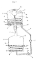
- a first container 1 and an upper, second container 2 are provided, which are connected to one another by a tube 3, conical in the exemplary embodiment.
- This tube 3 projects with its end with a smaller diameter from below about two-thirds up in the interior 2a of the container 2 into it.
- a pipeline 4 which lies from the bottom of the upstream, second container 2, leading to the underlying, first container 1 and opens at the bottom of a.
- a pump 5 In the pipe 4 is a pump 5 and an electric solenoid valve. 6
- Container 1 and container 2 are filled with a fluid (liquid medium) up to the level 12 and 13 respectively.
- the fluid 10 in the first container 1 is heated by the heat exchanger 8 and begins to evaporate.
- the vapor 11 rises in the container 1, enters the end of the conical tube 3 of larger diameter, flows through the conical tube 3 and enters the second container 2 from the narrower end of the tube 3.
- the end 2 a in the second container 2 of the conical tube 3 is associated with a motor 14 which is driven by the fluid vapor 11 flowing through the tube 3.
- the drive shaft 15 of the motor 14 is led out of the second container 2 in the embodiment shown in FIG.
- fluid vapor 11 After it has exited the motor 14, is cooled by the heat exchanger 9, so that the (fluid) vapor 11 in the container 2 condenses and collects in the container 2 at the bottom.
- a pipe 4 which extends from the bottom of the above, the second container 2 and connected to the underside of the container 1, Fluid 10 pumped from the second container 2 with the pump 5 in the first container 1.
- An electric solenoid valve 6 provided in the line 4 is controlled by a level control 7 arranged on the first container 1.
- the level control 7 has the task to return the differently occurring fluid 10 defined in the first container 1, so that the level 12 in the first container 1 and the level 13 in the second container 2 remain unchanged in order to prevent short-term pressure fluctuations.
- the electric solenoid valve 6 prevents at standstill of the arrangement, the outflow of fluid 10 from the upper lying second container 2 in the first container. 1
- shut-off element 16 is provided in the conical tube 3. This shut-off device 16 is closed when the arrangement is at a standstill (for example, breaks), so that the pressure of the vapor 11 formed by the evaporation of fluid 10 is maintained and the condensation space in the container 2 is kept unpressurized.
- startup times of the arrangement according to the invention can be kept short.
- the conical tube 3 is guided from above into the second container 2 located above. Also, the motor 14 is disposed outside of the container 2. Via a pipe 3a after the motor 14, fluid vapor 11 is returned to the upper, second container 2 via the upper side thereof.
- FIG. 3 shows schematically an embodiment of an arrangement according to the invention, in which the containers 1 and 2 are provided with heat fins 17 (container 1) and cooling fins 17 (container 2).
- first container 1 and the second container 2 may be arranged side by side.
- the fluid 10 in the first container 1 is heated with the heat exchanger 8, and the fluid 10 begins to evaporate.
- the fluid vapor 11 compresses and the pressure rises in the container 1.
- the located in the upper second container 2 fluid 10 is with a heat exchanger 9 cooled. Then, the fluid vapor 11 contained in the container 2 condenses and accumulates in the container 2. Due to the condensation of the fluid vapor 11, the pressure in the container 2 drops.
- fluid vapor 11 flows from the container 1 via the conically shaped tube 3, drives a motor 14 provided, for example, at the end of the (conically shaped) tube, and flows in (relaxed) the container 2 from.
- fluid 10 is not completely evaporated in the upper second container 2, with a pump 5 via the pipe 4, which goes off from the bottom of the upstream container 2 and at the bottom of the container 1, fluid 10 is pumped from the container 2 into the container 1, so that in the first container 1 vaporized fluid 10 is replaced.
- the level control 7 has the task to return the different accumulating fluid 10 exactly in the container 1, so that the level 12 in the container 1 and the level 13 in the container 2 remain unchanged in order to prevent short-term pressure fluctuations.
- An arrangement for converting heat into motion and optionally further into electrical current has two closed containers 1, 2.
- the containers 1, 2 are partially filled with a fluid 10.
- a heat exchanger 8 is provided, via which heat is supplied to evaporate the fluid 10.
- a heat exchanger 9 is provided to which a cooling medium is supplied to condense in the container 2 located fluid vapor 11 to 10 fluid.
- the container 1 is with its upper end over a conically tapered tube 3 is connected to the second container 2, so that from the container 1 fluid vapor 11 can flow into the container 2 and drive a motor 14 arranged there.
- the containers 1, 2 are further connected to each other via a pipe 4.
- the pipeline 4 starts from the lower, filled with fluid 10 region of the second container 2 and flows into the container 1 also below, in the area filled with liquid fluid 10.
- a level switch 7 is provided which controls a provided in the pipe 4 pump 5 and a shut-off 6 such that the level 12 of fluid 10 in the first container 1 and the level 13 of fluid 10 in the second container 2 are constant so that the heat exchangers 8 and 9 provided in the containers 1, 2 are only partially immersed in the liquid fluid 10. It is provided that the heat exchanger 8 is arranged in the container 1 predominantly in liquid fluid 10 and the heat exchanger 9 is arranged in the container 2 predominantly in the vapor space 11 of the container 2.
Landscapes
- Engineering & Computer Science (AREA)
- Combustion & Propulsion (AREA)
- Mechanical Engineering (AREA)
- General Engineering & Computer Science (AREA)
- Chemical & Material Sciences (AREA)
- Engine Equipment That Uses Special Cycles (AREA)
- Saccharide Compounds (AREA)
- Magnetic Resonance Imaging Apparatus (AREA)
- Diaphragms For Electromechanical Transducers (AREA)
- Inorganic Insulating Materials (AREA)
- Particle Formation And Scattering Control In Inkjet Printers (AREA)
- Amplifiers (AREA)
- Control Of Eletrric Generators (AREA)
- Filling Or Discharging Of Gas Storage Vessels (AREA)
Priority Applications (3)
| Application Number | Priority Date | Filing Date | Title |
|---|---|---|---|
| PL07450015T PL1930558T3 (pl) | 2006-02-06 | 2007-02-01 | Przetwornik energii |
| SI200730503T SI1930558T1 (sl) | 2006-02-06 | 2007-02-01 | Pretvornik energije |
| CY20111100149T CY1111360T1 (el) | 2006-02-06 | 2011-02-09 | Μετατροπεας ενεργειας |
Applications Claiming Priority (1)
| Application Number | Priority Date | Filing Date | Title |
|---|---|---|---|
| AT0017506A AT503167B1 (de) | 2006-02-06 | 2006-02-06 | Anordnung zum umwandeln von strömungsenergie |
Publications (2)
| Publication Number | Publication Date |
|---|---|
| EP1930558A1 true EP1930558A1 (fr) | 2008-06-11 |
| EP1930558B1 EP1930558B1 (fr) | 2010-11-10 |
Family
ID=38328672
Family Applications (1)
| Application Number | Title | Priority Date | Filing Date |
|---|---|---|---|
| EP07450015A Not-in-force EP1930558B1 (fr) | 2006-02-06 | 2007-02-01 | Convertisseur d'énergie |
Country Status (9)
| Country | Link |
|---|---|
| EP (1) | EP1930558B1 (fr) |
| AT (2) | AT503167B1 (fr) |
| CY (1) | CY1111360T1 (fr) |
| DE (1) | DE502007005606D1 (fr) |
| DK (1) | DK1930558T3 (fr) |
| ES (1) | ES2356616T3 (fr) |
| PL (1) | PL1930558T3 (fr) |
| PT (1) | PT1930558E (fr) |
| SI (1) | SI1930558T1 (fr) |
Cited By (4)
| Publication number | Priority date | Publication date | Assignee | Title |
|---|---|---|---|---|
| WO2012000002A2 (fr) | 2010-07-01 | 2012-01-05 | Psw Systems Ag | Système pour transformer de l'énergie thermique et dispositif pour réchauffer et refroidir un milieu |
| WO2017041147A1 (fr) * | 2015-09-08 | 2017-03-16 | Atlas Copco Airpower, Naamloze Vennootschap | Cycle de rankine à caloporteur organique (orc) permettant de transformer une chaleur résiduelle provenant d'une source de chaleur en énergie mécanique et système de refroidissement utilisant un tel orc |
| BE1023753B1 (nl) * | 2015-09-08 | 2017-07-11 | Atlas Copco Airpower Naamloze Vennootschap | Orc om afvalwarmte van een warmtebron om te vormen in mechanische energie en koelsysteem dat van een dergelijke orc gebruikmaakt |
| WO2017192103A1 (fr) * | 2016-05-05 | 2017-11-09 | Şan Mehmet | Chaudière combinée chaleur-vapeur |
Families Citing this family (2)
| Publication number | Priority date | Publication date | Assignee | Title |
|---|---|---|---|---|
| US11897637B2 (en) * | 2021-01-08 | 2024-02-13 | Ivaylo Trendafilov Vasilev | System and method of generating a momentum change in a vehicle by phase changing matter in a closed system |
| US12084992B2 (en) * | 2022-11-04 | 2024-09-10 | Kantilal Khatri | Clean electricity generating system and method |
Citations (6)
| Publication number | Priority date | Publication date | Assignee | Title |
|---|---|---|---|---|
| DE2943686A1 (de) * | 1979-10-30 | 1981-07-02 | Erwin 8014 Neubiberg Veldung | Industrieabwaermekraftwerk |
| JPS57148011A (en) * | 1981-03-09 | 1982-09-13 | Koji Akagawa | Motive power generator employing low-temperature energy source for natural circulating force |
| EP0370587A2 (fr) * | 1986-12-23 | 1990-05-30 | Chiyoda Chemical Engineering & Construction Company Limited | Appareil de production d'énergie électrique utilisant un alliage pouvant stocker de l'hydrogène |
| EP1217293A1 (fr) * | 2000-12-15 | 2002-06-26 | Gastec N.V. | Méthode pour faire fonctionner un appareil à énergie totale, et appareil à énergie totale à haute pression sans pompe |
| WO2006007733A1 (fr) * | 2004-07-23 | 2006-01-26 | New World Generation Inc. | Centrale electrique a milieu de stockage thermique |
| WO2006078419A1 (fr) * | 2004-12-22 | 2006-07-27 | Hines, Garold, Paul | Systeme et procede de generation en ligne geothermique et hydroelectrique |
Family Cites Families (1)
| Publication number | Priority date | Publication date | Assignee | Title |
|---|---|---|---|---|
| EP1075630A4 (fr) * | 1997-11-10 | 2003-05-02 | Jeffrey Stephen Sterling | Systemes et procedes de transformation de l'energie thermique |
-
2006
- 2006-02-06 AT AT0017506A patent/AT503167B1/de not_active IP Right Cessation
-
2007
- 2007-02-01 PT PT07450015T patent/PT1930558E/pt unknown
- 2007-02-01 SI SI200730503T patent/SI1930558T1/sl unknown
- 2007-02-01 DK DK07450015.8T patent/DK1930558T3/da active
- 2007-02-01 ES ES07450015T patent/ES2356616T3/es active Active
- 2007-02-01 DE DE502007005606T patent/DE502007005606D1/de active Active
- 2007-02-01 EP EP07450015A patent/EP1930558B1/fr not_active Not-in-force
- 2007-02-01 PL PL07450015T patent/PL1930558T3/pl unknown
- 2007-02-01 AT AT07450015T patent/ATE487851T1/de active
-
2011
- 2011-02-09 CY CY20111100149T patent/CY1111360T1/el unknown
Patent Citations (6)
| Publication number | Priority date | Publication date | Assignee | Title |
|---|---|---|---|---|
| DE2943686A1 (de) * | 1979-10-30 | 1981-07-02 | Erwin 8014 Neubiberg Veldung | Industrieabwaermekraftwerk |
| JPS57148011A (en) * | 1981-03-09 | 1982-09-13 | Koji Akagawa | Motive power generator employing low-temperature energy source for natural circulating force |
| EP0370587A2 (fr) * | 1986-12-23 | 1990-05-30 | Chiyoda Chemical Engineering & Construction Company Limited | Appareil de production d'énergie électrique utilisant un alliage pouvant stocker de l'hydrogène |
| EP1217293A1 (fr) * | 2000-12-15 | 2002-06-26 | Gastec N.V. | Méthode pour faire fonctionner un appareil à énergie totale, et appareil à énergie totale à haute pression sans pompe |
| WO2006007733A1 (fr) * | 2004-07-23 | 2006-01-26 | New World Generation Inc. | Centrale electrique a milieu de stockage thermique |
| WO2006078419A1 (fr) * | 2004-12-22 | 2006-07-27 | Hines, Garold, Paul | Systeme et procede de generation en ligne geothermique et hydroelectrique |
Cited By (7)
| Publication number | Priority date | Publication date | Assignee | Title |
|---|---|---|---|---|
| WO2012000002A2 (fr) | 2010-07-01 | 2012-01-05 | Psw Systems Ag | Système pour transformer de l'énergie thermique et dispositif pour réchauffer et refroidir un milieu |
| WO2017041147A1 (fr) * | 2015-09-08 | 2017-03-16 | Atlas Copco Airpower, Naamloze Vennootschap | Cycle de rankine à caloporteur organique (orc) permettant de transformer une chaleur résiduelle provenant d'une source de chaleur en énergie mécanique et système de refroidissement utilisant un tel orc |
| BE1023753B1 (nl) * | 2015-09-08 | 2017-07-11 | Atlas Copco Airpower Naamloze Vennootschap | Orc om afvalwarmte van een warmtebron om te vormen in mechanische energie en koelsysteem dat van een dergelijke orc gebruikmaakt |
| CN108474272A (zh) * | 2015-09-08 | 2018-08-31 | 阿特拉斯·科普柯空气动力股份有限公司 | 将热源废热转换成机械能的orc及采用orc的冷却系统 |
| US10612423B2 (en) | 2015-09-08 | 2020-04-07 | Atlas Copco Airpower, Naamloze Vennootschap | ORC for transporting waste heat from a heat source into mechanical energy and cooling system making use of such an ORC |
| CN108474272B (zh) * | 2015-09-08 | 2020-08-14 | 阿特拉斯·科普柯空气动力股份有限公司 | 将热源废热转换成机械能的orc及采用orc的冷却系统 |
| WO2017192103A1 (fr) * | 2016-05-05 | 2017-11-09 | Şan Mehmet | Chaudière combinée chaleur-vapeur |
Also Published As
| Publication number | Publication date |
|---|---|
| EP1930558B1 (fr) | 2010-11-10 |
| SI1930558T1 (sl) | 2011-03-31 |
| CY1111360T1 (el) | 2015-08-05 |
| PT1930558E (pt) | 2011-02-15 |
| DE502007005606D1 (de) | 2010-12-23 |
| DK1930558T3 (da) | 2011-02-28 |
| ES2356616T3 (es) | 2011-04-11 |
| PL1930558T3 (pl) | 2011-05-31 |
| AT503167A1 (de) | 2007-08-15 |
| AT503167B1 (de) | 2007-10-15 |
| ATE487851T1 (de) | 2010-11-15 |
Similar Documents
| Publication | Publication Date | Title |
|---|---|---|
| EP1930558B1 (fr) | Convertisseur d'énergie | |
| DE68926220T2 (de) | Verfahren und Vorrichtung zur Dampfkrafterzeugung | |
| EP0773349B1 (fr) | Générateur de vapeur à hélice pour centrales | |
| DE102013009351B3 (de) | Anlage und Verfahren zur Rückgewinnung von Energie aus Wärme in einem thermodynamischen Kreisprozess | |
| EP1159512B1 (fr) | Element d'expansion de gaz pour un dispositif de transformation d'energie thermique en energie motrice, notamment pour un moteur a eau chaude | |
| DE102009010020B4 (de) | Speisewasserentgaser eines solarthermischen Kraftwerks | |
| DE2344428A1 (de) | Waermeuebertragungseinrichtung | |
| EP2561276A2 (fr) | Procédé à cycle de rankine (rc) ou à cycle de rankine organique (orc) pour la transformation en énergie électrique de la chaleur produite lors de la combustion de biomasse et dispositif correspondant | |
| DE102009043720A1 (de) | Carnotisierter Rankineprozess für Solarthermische Kraftwerke | |
| DE102010011737B4 (de) | Verfahren und Vorrichtung zur Energieumwandlung | |
| WO2011085914A2 (fr) | Dispositif pour fournir de la chaleur de chauffage ou pour produire du froid de climatisation et dispositif pour fournir de l'énergie électrique, et procédé pour fournir de l'énergie de chauffage, procédé pour produire de l'énergie de réfrigération et procédé pour produire de l'énergie cinétique et/ou de l'énergie électrique | |
| DE102011116338B4 (de) | Solarthermisches Kraftwerk sowie Verfahren zum Betreiben eines solarthermischen Kraftwerks | |
| DE3212608A1 (de) | Speicherheizungsanlage mit sorptionsspeicher | |
| DE3035207C2 (de) | Wärmepumpe | |
| WO2012152602A1 (fr) | Circuit de conduite et procédé permettant de faire fonctionner un circuit de conduite destiné à récupérer la chaleur dissipée d'un moteur à combustion interne | |
| WO2019001645A1 (fr) | Centrale de production d'énergie électrique | |
| WO2006050714A2 (fr) | Dispositif pour faire passer un milieu de travail de l'etat liquide a l'etat de vapeur | |
| EP2730755B1 (fr) | Installation destinée à l'utilisation d'énergie thermique | |
| AT508933B1 (de) | Anordnung zum umwandeln thermischer energie (wärme) in strömungskraft | |
| AT509080B1 (de) | Anordnung zum umwandeln thermischer energie in bewegung | |
| DE10361318A1 (de) | Anlage zur Entsalzung von Meerwasser | |
| WO2019072549A1 (fr) | Récepteur, centrale électrique et procédé d'utilisation thermique de l'énergie solaire | |
| DE102009057179A1 (de) | Dampf-Flüssigkeits-Triebwerk | |
| DE10160593B4 (de) | Wärmekraftanlage | |
| EP3147466B1 (fr) | Machine a energie hydraulique |
Legal Events
| Date | Code | Title | Description |
|---|---|---|---|
| PUAI | Public reference made under article 153(3) epc to a published international application that has entered the european phase |
Free format text: ORIGINAL CODE: 0009012 |
|
| AK | Designated contracting states |
Kind code of ref document: A1 Designated state(s): AT BE BG CH CY CZ DE DK EE ES FI FR GB GR HU IE IS IT LI LT LU LV MC NL PL PT RO SE SI SK TR |
|
| AX | Request for extension of the european patent |
Extension state: AL BA HR MK RS |
|
| 17P | Request for examination filed |
Effective date: 20080805 |
|
| AKX | Designation fees paid |
Designated state(s): AT BE BG CH CY CZ DE DK EE ES FI FR GB GR HU IE IS IT LI LT LU LV MC NL PL PT RO SE SI SK TR |
|
| GRAP | Despatch of communication of intention to grant a patent |
Free format text: ORIGINAL CODE: EPIDOSNIGR1 |
|
| GRAS | Grant fee paid |
Free format text: ORIGINAL CODE: EPIDOSNIGR3 |
|
| GRAA | (expected) grant |
Free format text: ORIGINAL CODE: 0009210 |
|
| AK | Designated contracting states |
Kind code of ref document: B1 Designated state(s): AT BE BG CH CY CZ DE DK EE ES FI FR GB GR HU IE IS IT LI LT LU LV MC NL PL PT RO SE SI SK TR |
|
| REG | Reference to a national code |
Ref country code: GB Ref legal event code: FG4D Free format text: NOT ENGLISH |
|
| REG | Reference to a national code |
Ref country code: CH Ref legal event code: EP |
|
| REG | Reference to a national code |
Ref country code: IE Ref legal event code: FG4D Free format text: LANGUAGE OF EP DOCUMENT: GERMAN |
|
| REF | Corresponds to: |
Ref document number: 502007005606 Country of ref document: DE Date of ref document: 20101223 Kind code of ref document: P |
|
| REG | Reference to a national code |
Ref country code: RO Ref legal event code: EPE |
|
| REG | Reference to a national code |
Ref country code: PT Ref legal event code: SC4A Free format text: AVAILABILITY OF NATIONAL TRANSLATION Effective date: 20110208 Ref country code: CH Ref legal event code: PUE Owner name: PSW SYSTEMS AG Free format text: PRUGNER, SIEGFRIED#ALTENBERG 64#8295 ST. JOHANN IN DER HAIDE (AT) -TRANSFER TO- PSW SYSTEMS AG#GEWERBESTRASSE 5#6330 CHAM (CH) |
|
| REG | Reference to a national code |
Ref country code: NL Ref legal event code: T3 |
|
| REG | Reference to a national code |
Ref country code: DK Ref legal event code: T3 Ref country code: CH Ref legal event code: NV Representative=s name: RIEDERER HASLER & PARTNER PATENTANWAELTE AG |
|
| REG | Reference to a national code |
Ref country code: SE Ref legal event code: TRGR |
|
| REG | Reference to a national code |
Ref country code: PT Ref legal event code: PC4A Owner name: PSW SYSTEMS AG, CH Effective date: 20110302 |
|
| RAP2 | Party data changed (patent owner data changed or rights of a patent transferred) |
Owner name: PSW SYSTEMS AG |
|
| RIN2 | Information on inventor provided after grant (corrected) |
Inventor name: PRUGNER, SIEGFRIED |
|
| REG | Reference to a national code |
Ref country code: NL Ref legal event code: SD Effective date: 20110314 |
|
| REG | Reference to a national code |
Ref country code: ES Ref legal event code: FG2A Ref document number: 2356616 Country of ref document: ES Kind code of ref document: T3 Effective date: 20110411 |
|
| REG | Reference to a national code |
Ref country code: GR Ref legal event code: EP Ref document number: 20110400315 Country of ref document: GR Effective date: 20110317 |
|
| PGFP | Annual fee paid to national office [announced via postgrant information from national office to epo] |
Ref country code: MC Payment date: 20110216 Year of fee payment: 5 Ref country code: LT Payment date: 20110209 Year of fee payment: 5 Ref country code: DK Payment date: 20110210 Year of fee payment: 5 |
|
| REG | Reference to a national code |
Ref country code: GB Ref legal event code: 732E Free format text: REGISTERED BETWEEN 20110407 AND 20110413 |
|
| REG | Reference to a national code |
Ref country code: SK Ref legal event code: T3 Ref document number: E 8782 Country of ref document: SK |
|
| PGFP | Annual fee paid to national office [announced via postgrant information from national office to epo] |
Ref country code: IS Payment date: 20110215 Year of fee payment: 5 Ref country code: LU Payment date: 20110215 Year of fee payment: 5 Ref country code: LV Payment date: 20110202 Year of fee payment: 5 Ref country code: CH Payment date: 20110128 Year of fee payment: 5 Ref country code: CZ Payment date: 20110131 Year of fee payment: 5 |
|
| REG | Reference to a national code |
Ref country code: PL Ref legal event code: T3 |
|
| REG | Reference to a national code |
Ref country code: HU Ref legal event code: AG4A Ref document number: E010239 Country of ref document: HU |
|
| PGFP | Annual fee paid to national office [announced via postgrant information from national office to epo] |
Ref country code: EE Payment date: 20110203 Year of fee payment: 5 |
|
| PLBE | No opposition filed within time limit |
Free format text: ORIGINAL CODE: 0009261 |
|
| STAA | Information on the status of an ep patent application or granted ep patent |
Free format text: STATUS: NO OPPOSITION FILED WITHIN TIME LIMIT |
|
| 26N | No opposition filed |
Effective date: 20110811 |
|
| PGFP | Annual fee paid to national office [announced via postgrant information from national office to epo] |
Ref country code: CY Payment date: 20110216 Year of fee payment: 5 |
|
| REG | Reference to a national code |
Ref country code: SI Ref legal event code: SP73 Owner name: PSW SYSTEMS AG; CH Effective date: 20111024 |
|
| REG | Reference to a national code |
Ref country code: DE Ref legal event code: R097 Ref document number: 502007005606 Country of ref document: DE Effective date: 20110811 |
|
| LTIE | Lt: invalidation of european patent or patent extension | ||
| PG25 | Lapsed in a contracting state [announced via postgrant information from national office to epo] |
Ref country code: MC Free format text: LAPSE BECAUSE OF NON-PAYMENT OF DUE FEES Effective date: 20120229 |
|
| REG | Reference to a national code |
Ref country code: EE Ref legal event code: MM4A Ref document number: E005362 Country of ref document: EE Effective date: 20120228 |
|
| PG25 | Lapsed in a contracting state [announced via postgrant information from national office to epo] |
Ref country code: LT Free format text: LAPSE BECAUSE OF NON-PAYMENT OF DUE FEES Effective date: 20120201 Ref country code: EE Free format text: LAPSE BECAUSE OF NON-PAYMENT OF DUE FEES Effective date: 20120228 |
|
| PGFP | Annual fee paid to national office [announced via postgrant information from national office to epo] |
Ref country code: GB Payment date: 20120731 Year of fee payment: 6 Ref country code: FI Payment date: 20120802 Year of fee payment: 6 Ref country code: IE Payment date: 20120731 Year of fee payment: 6 Ref country code: RO Payment date: 20120731 Year of fee payment: 6 Ref country code: SE Payment date: 20120731 Year of fee payment: 6 |
|
| PG25 | Lapsed in a contracting state [announced via postgrant information from national office to epo] |
Ref country code: LV Free format text: LAPSE BECAUSE OF NON-PAYMENT OF DUE FEES Effective date: 20120201 |
|
| PGFP | Annual fee paid to national office [announced via postgrant information from national office to epo] |
Ref country code: SK Payment date: 20120731 Year of fee payment: 6 Ref country code: SI Payment date: 20120731 Year of fee payment: 6 Ref country code: TR Payment date: 20120731 Year of fee payment: 6 Ref country code: BG Payment date: 20120731 Year of fee payment: 6 Ref country code: GR Payment date: 20120731 Year of fee payment: 6 Ref country code: PL Payment date: 20120731 Year of fee payment: 6 |
|
| PGFP | Annual fee paid to national office [announced via postgrant information from national office to epo] |
Ref country code: BE Payment date: 20120810 Year of fee payment: 6 Ref country code: HU Payment date: 20120727 Year of fee payment: 6 Ref country code: DE Payment date: 20120801 Year of fee payment: 6 Ref country code: IT Payment date: 20120731 Year of fee payment: 6 Ref country code: FR Payment date: 20120822 Year of fee payment: 6 Ref country code: ES Payment date: 20120731 Year of fee payment: 6 |
|
| PGFP | Annual fee paid to national office [announced via postgrant information from national office to epo] |
Ref country code: NL Payment date: 20120731 Year of fee payment: 6 Ref country code: PT Payment date: 20120502 Year of fee payment: 6 |
|
| PGFP | Annual fee paid to national office [announced via postgrant information from national office to epo] |
Ref country code: AT Payment date: 20120801 Year of fee payment: 6 |
|
| REG | Reference to a national code |
Ref country code: PT Ref legal event code: MM4A Free format text: LAPSE DUE TO NON-PAYMENT OF FEES Effective date: 20130801 |
|
| BERE | Be: lapsed |
Owner name: PSW SYSTEMS A.G. Effective date: 20130228 |
|
| REG | Reference to a national code |
Ref country code: NL Ref legal event code: V1 Effective date: 20130901 |
|
| REG | Reference to a national code |
Ref country code: DK Ref legal event code: EBP |
|
| REG | Reference to a national code |
Ref country code: CH Ref legal event code: PL |
|
| REG | Reference to a national code |
Ref country code: SE Ref legal event code: EUG |
|
| REG | Reference to a national code |
Ref country code: AT Ref legal event code: MM01 Ref document number: 487851 Country of ref document: AT Kind code of ref document: T Effective date: 20130228 |
|
| REG | Reference to a national code |
Ref country code: GR Ref legal event code: ML Ref document number: 20110400315 Country of ref document: GR Effective date: 20130904 |
|
| GBPC | Gb: european patent ceased through non-payment of renewal fee |
Effective date: 20130201 |
|
| REG | Reference to a national code |
Ref country code: SI Ref legal event code: KO00 Effective date: 20130904 |
|
| PG25 | Lapsed in a contracting state [announced via postgrant information from national office to epo] |
Ref country code: IS Free format text: LAPSE BECAUSE OF FAILURE TO SUBMIT A TRANSLATION OF THE DESCRIPTION OR TO PAY THE FEE WITHIN THE PRESCRIBED TIME-LIMIT Effective date: 20130829 Ref country code: FI Free format text: LAPSE BECAUSE OF NON-PAYMENT OF DUE FEES Effective date: 20130201 Ref country code: AT Free format text: LAPSE BECAUSE OF NON-PAYMENT OF DUE FEES Effective date: 20130228 Ref country code: NL Free format text: LAPSE BECAUSE OF NON-PAYMENT OF DUE FEES Effective date: 20130901 Ref country code: SI Free format text: LAPSE BECAUSE OF NON-PAYMENT OF DUE FEES Effective date: 20130202 Ref country code: SE Free format text: LAPSE BECAUSE OF NON-PAYMENT OF DUE FEES Effective date: 20130202 Ref country code: CH Free format text: LAPSE BECAUSE OF NON-PAYMENT OF DUE FEES Effective date: 20130228 Ref country code: LI Free format text: LAPSE BECAUSE OF NON-PAYMENT OF DUE FEES Effective date: 20130228 Ref country code: SK Free format text: LAPSE BECAUSE OF NON-PAYMENT OF DUE FEES Effective date: 20130201 Ref country code: PT Free format text: LAPSE BECAUSE OF NON-PAYMENT OF DUE FEES Effective date: 20130801 Ref country code: GR Free format text: LAPSE BECAUSE OF NON-PAYMENT OF DUE FEES Effective date: 20130904 Ref country code: CZ Free format text: LAPSE BECAUSE OF NON-PAYMENT OF DUE FEES Effective date: 20130201 Ref country code: HU Free format text: LAPSE BECAUSE OF NON-PAYMENT OF DUE FEES Effective date: 20130202 |
|
| REG | Reference to a national code |
Ref country code: SK Ref legal event code: MM4A Ref document number: E 8782 Country of ref document: SK Effective date: 20130201 |
|
| REG | Reference to a national code |
Ref country code: FR Ref legal event code: ST Effective date: 20131031 |
|
| PG25 | Lapsed in a contracting state [announced via postgrant information from national office to epo] |
Ref country code: CY Free format text: LAPSE BECAUSE OF NON-PAYMENT OF DUE FEES Effective date: 20130201 |
|
| REG | Reference to a national code |
Ref country code: IE Ref legal event code: MM4A |
|
| REG | Reference to a national code |
Ref country code: DE Ref legal event code: R119 Ref document number: 502007005606 Country of ref document: DE Effective date: 20130903 |
|
| PG25 | Lapsed in a contracting state [announced via postgrant information from national office to epo] |
Ref country code: IT Free format text: LAPSE BECAUSE OF NON-PAYMENT OF DUE FEES Effective date: 20130201 |
|
| PG25 | Lapsed in a contracting state [announced via postgrant information from national office to epo] |
Ref country code: DK Free format text: LAPSE BECAUSE OF NON-PAYMENT OF DUE FEES Effective date: 20130228 Ref country code: DE Free format text: LAPSE BECAUSE OF NON-PAYMENT OF DUE FEES Effective date: 20130903 Ref country code: IE Free format text: LAPSE BECAUSE OF NON-PAYMENT OF DUE FEES Effective date: 20130201 Ref country code: FR Free format text: LAPSE BECAUSE OF NON-PAYMENT OF DUE FEES Effective date: 20130228 Ref country code: BE Free format text: LAPSE BECAUSE OF NON-PAYMENT OF DUE FEES Effective date: 20130228 Ref country code: GB Free format text: LAPSE BECAUSE OF NON-PAYMENT OF DUE FEES Effective date: 20130201 |
|
| PG25 | Lapsed in a contracting state [announced via postgrant information from national office to epo] |
Ref country code: RO Free format text: LAPSE BECAUSE OF NON-PAYMENT OF DUE FEES Effective date: 20130201 |
|
| PG25 | Lapsed in a contracting state [announced via postgrant information from national office to epo] |
Ref country code: LU Free format text: LAPSE BECAUSE OF NON-PAYMENT OF DUE FEES Effective date: 20120201 Ref country code: PL Free format text: LAPSE BECAUSE OF NON-PAYMENT OF DUE FEES Effective date: 20130201 |
|
| REG | Reference to a national code |
Ref country code: PL Ref legal event code: LAPE |
|
| REG | Reference to a national code |
Ref country code: ES Ref legal event code: FD2A Effective date: 20140609 |
|
| PG25 | Lapsed in a contracting state [announced via postgrant information from national office to epo] |
Ref country code: ES Free format text: LAPSE BECAUSE OF NON-PAYMENT OF DUE FEES Effective date: 20130202 |
|
| PG25 | Lapsed in a contracting state [announced via postgrant information from national office to epo] |
Ref country code: BG Free format text: LAPSE BECAUSE OF NON-PAYMENT OF DUE FEES Effective date: 20130228 |
|
| PG25 | Lapsed in a contracting state [announced via postgrant information from national office to epo] |
Ref country code: TR Free format text: LAPSE BECAUSE OF NON-PAYMENT OF DUE FEES Effective date: 20130201 |