EP1932411B1 - Verrou automatique pour couplage rapide de crochet en trois points et module de connexion PTO - Google Patents
Verrou automatique pour couplage rapide de crochet en trois points et module de connexion PTO Download PDFInfo
- Publication number
- EP1932411B1 EP1932411B1 EP07123261A EP07123261A EP1932411B1 EP 1932411 B1 EP1932411 B1 EP 1932411B1 EP 07123261 A EP07123261 A EP 07123261A EP 07123261 A EP07123261 A EP 07123261A EP 1932411 B1 EP1932411 B1 EP 1932411B1
- Authority
- EP
- European Patent Office
- Prior art keywords
- implement
- hitch
- quick coupler
- tractor
- pto
- Prior art date
- Legal status (The legal status is an assumption and is not a legal conclusion. Google has not performed a legal analysis and makes no representation as to the accuracy of the status listed.)
- Not-in-force
Links
Images






Classifications
-
- A—HUMAN NECESSITIES
- A01—AGRICULTURE; FORESTRY; ANIMAL HUSBANDRY; HUNTING; TRAPPING; FISHING
- A01B—SOIL WORKING IN AGRICULTURE OR FORESTRY; PARTS, DETAILS, OR ACCESSORIES OF AGRICULTURAL MACHINES OR IMPLEMENTS, IN GENERAL
- A01B59/00—Devices specially adapted for connection between animals or tractors and agricultural machines or implements
- A01B59/002—Details, component parts
- A01B59/006—Latched hooks
-
- A—HUMAN NECESSITIES
- A01—AGRICULTURE; FORESTRY; ANIMAL HUSBANDRY; HUNTING; TRAPPING; FISHING
- A01B—SOIL WORKING IN AGRICULTURE OR FORESTRY; PARTS, DETAILS, OR ACCESSORIES OF AGRICULTURAL MACHINES OR IMPLEMENTS, IN GENERAL
- A01B71/00—Construction or arrangement of setting or adjusting mechanisms, of implement or tool drive or of power take-off; Means for protecting parts against dust, or the like; Adapting machine elements to or for agricultural purposes
- A01B71/06—Special adaptations of coupling means between power take-off and transmission shaft to the implement or machine
- A01B71/063—Special adaptations of coupling means between power take-off and transmission shaft to the implement or machine for enabling transmission coupling and connection between tractor and implements to be controlled from the driver's seat
Definitions
- the present invention relates generally to coupling devices for connecting a tractor or other similar prime mover to a hitch-mounted implement, and more particularly to a quick-attaching coupler and power takeoff apparatus for automatically coupling a hitch-mounted implement and engaging the power takeoff.
- Quick attaching couplers have been developed to allow faster attachment of hitch mounted implements to a tractor.
- Many quick attaching couplers comprise an inverted U-shape arched frame that is attached to the conventional three pivot points of a tractor hitch.
- the quick attaching coupler frame includes an upper hook with a long, tapered point and two lower coupling hooks or jaws with a latching and unlatching arrangement to hold the implement hitch pins.
- the coupler is lowered by positioning the tractor's three point hitch and the tractor positioned near the implement with the coupling hooks adjacent the implement hitching pins.
- the hitch and connected quick coupler is then raised with the tractor hydraulic system so that the upper hook begins to engage the upper pin on the implement. Further lifting, assuming all three connection points are aligned, causes the weight of the implement to force the lower hitch pins to enter the lower hooks where they may be latched in place by the tractor operator to secure the implement.
- the latches may be spring loaded to the locked or latched position. Locking the latches may be accomplished by having the operator dismount the tractor seat to manually operate two locking mechanisms for the two hitch pins. Some quick attaching couplers incorporate one or more levers that enable the operator to remain seated on the tractor while locking the latches.
- Tractors may be equipped with a power take off (hereinafter "PTO") drive that provides a mechanism for transmitting rotary power from the engine to implements that are coupled to a tractor.
- PTO power take off
- the PTO is most commonly a rotating splined shaft which projects rearwardly from the rear of the tractor frame for a short distance; however, some tractors have auxiliary PTO shafts at other locations, such as at the front of the tractor.
- the direction of rotation, rotational speed, approximate location and exact dimensions of the PTO shaft are standardized to provide the ability to interchange between power shafts of various implements made by different manufacturers.
- the PTO shaft of a tractor is typically driven at either 540 rpm or 1,000 rpm.
- a driveline comprised of a telescoping, splined drive shaft which can be extended to connect at one end to the splined interface of the tractor's PTO while the other end connects to the rotary input connection (typically a gearbox input) for the implement.
- the driveline typically includes two or more universal or constant velocity joints, or the like, to allow angular movement of the implement and tractor relative to one another without binding the driveline.
- Connecting the PTO driveline assembly to the tractor PTO can be cumbersome, especially in the case of three point hitch-mounted implements which may have limited accessibility to the PTO connection area.
- the object of a quick attaching coupler is to simplify the process of connecting an implement to a tractor hitch; however, requiring an operator to manually connect the PTO imposes a sometimes difficult and time-consuming task in the hitching process thereby diminishing some benefits of the quick attaching coupler.
- Connecting the driveline generally requires that the implement drive shaft be lifted into position for engaging the PTO splined connection. The drive shaft must often be manually rotated to align the splines while simultaneously holding the weight of the driveline assembly. This task is time consuming, dirty, and often difficult for the operator, particularly if he/she is of small physical stature or handicapped. Performing the task may also increase the potential for operator injury.
- EP-A-1 637 024 discloses a quick attaching coupler including an actuator that moves two latches, one on both sides of a hitch, between a first unlatched and a second latched position to receive and release implement pins, a quick PTO coupler mounted to the quick attaching coupler having a sleeve carrying a first end of a tractor PTO shaft, and a second actuator that moves the sleeve between a first PTO disengaged and a second PTO engaged position.
- an apparatus according to claim 1 is provided.
- the system may further comprise a spring assisted, latching lever moveable between a latched and an unlatched position.
- the rolling block may have a cam-like profile and a hook structure operable to restrain said bottom hitch pins when in said engaged position, and allowing said bottom hitch pins (23) to disengage when in said released position.
- FIGURE 1 shows tractor 10 having a three-point hitch 12 for selectively positioning a connected implement 20.
- Three-point hitch 12 includes lower lift arms 13 (only one shown) and upper link 15 which may be selectively raised and lowered with respect to the ground to position connected implement 20 at a desired height relative to the ground.
- Quick coupler 30 interposed between three-point hitch 12 and connected implement 20 to enable the implement 20 to be quickly connected to the tractor 10 with minimal operator effort.
- Quick couplers are well-known in the art, particularly those having design criteria set by ANSI standard ASAE S278.6 to assure compatibility among manufacturers.
- Implement 20 is attached to quick coupler 30 by implement hitch frame 22.
- implement 20 is a powered implement, such as a spreader, rotary mower, rotary tiller and the like, which receives rotary input power from tractor PTO 16.
- Rotary motion is transferred from the tractor PTO 16 to the implement via a PTO driveline comprising telescoping shaft 18, PTO connection module 50, and implement driveline 24.
- quick coupler 30 is shown having a main frame 32 which is generally an inverted U-shaped frame including spaced-apart connections for pivotable connection to the lower lift arms 13 and upper link 15 of the tractor's three-point hitch 12.
- the plane of the main frame 32 is generally transversely and vertically disposed with respect to the tractor, being adjacent to the tractor in one direction and adjacent to the implement in the opposite direction.
- Top hook 35 and a pair of releasable hitching mechanisms 40 are connected to the main frame 32 facing the implement 20 for engaging with implement top 21 and bottom hitch pins 23.
- the top hook 35 is connected to the cross member of the inverted U-shape portion of the main frame 32 while the releasable hitching mechanisms 40 are attached one on each opposing leg of the frame.
- Each releasable hitching mechanism 40 includes a bottom guide structure 36 housing a pivotally disposed rolling block 37 to secure the bottom hitch pins 23 of the implement in position, when engaged, to prevent the implement from inadvertently disconnecting from the quick coupler 30.
- Motion of the rolling blocks 37 is managed by a latching mechanism 41. Extreme limits of rolling block 37 motion are controlled by travel stops 39 which are integrated into the guide structure 36.
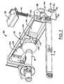
- PTO connection module 50 is connected to a transverse frame 52 which in turn connects to and spans between the vertical side members of the main frame 32.
- Transverse frame 52 provides a mounting location for the drive member of a torque coupler 60 and the PTO connection module 50 of the invention (illustrated in FIGURES 5 through 9 ).
- An opening 54 in transverse frame 52 allows the PTO driveline to pass through the frame so rotational motion may be transferred from the tractor PTO to the implement driveline through the torque coupler 60.
- Transverse frame 52 may be connected to the main frame 32 using bolted connections or may be integral to the quick coupler main frame 32. Though shown as a structural member spanning between the vertical side members of the inverted U-shaped main frame, numerous structures are conceivable and capable of providing a rigid mounting location for the PTO connection module 50.
- Implement frame 22 includes a transversely disposed driveline mounting structure 26 to provide a connection location for the implement driveline 24 (shown in FIGURE 1 ) and the driven member 80 of the torque coupling 60.
- Implement driveline bearing 28 connects implement driveline 24 to the mounting structure 26.
- Implement driveline bearing 28 locates the driveline in both radial and axial directions, thereby maintaining the driven member 80 of the torque coupling in a generally fixed position relative to the implement frame 22.
- Mounting structure 26 may also include driveline shields 29 which create a recessed structure surrounding the torque coupling 60. As the implement 20 is connected to the tractor quick coupler 30, the drive shields 29 are positioned such that they extend toward and adjacent to the top and bottom portions of the transverse frame 52.
- the drive shields 29 form an enclosure around the torque coupling 60 consisting of the transverse frame 52, the driveline mounting structure 26, and the drive shields 29 which prevent inadvertent contact with the rotating torque coupling 60 during implement operation.
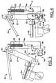
- Each releasable hitching mechanism 40 comprises guide structure 36, pivotable rolling block 37, latching lever 42, latching spring 44, actuator rod 46, and latch 38.
- the latching lever 42 is in the latched position and the rolling block 37 is in the released position.
- Latching lever 42 includes a cam-like profile and an offset pin connection for connection with actuator rod 46 so that movement of latching lever 42 between latched and unlatched positions allows movement of actuator rod 46 in upward and downward directions relating to released and engaged positions, respectively, of the rolling block 37.
- latching lever 42 The cam-like profile of latching lever 42 is generally held in contact with the main frame 32 by latching spring 44.
- latching spring 44 When latching lever 42 is positioned in the unlatched position as shown in FIGURE 6 , latching spring 44 is in a compressed condition and latch 38 is positioned to allow rolling block 37 to move between engaged and released positions relative to implement lower hitch pin 23.
- Latch 38 is shown in FIGURES 2 and 3 in an intermediate position, prevented from moving into the latched position by the contour of the rolling block 37 when it is in the released position as would be the case when the coupler is prepared for implement connection, but still prior to coupling an implement.
- spring force from latching spring 44 is transmitted to latch 38 by actuator rod 46 to maintain latch 38 in contact with the outer contour of rolling block 37. Friction between latch 38 and rolling block 37 maintains rolling block 37 in the released position ready to receive the implement bottom hitch pins 23.
- Movement of rolling block 37 from released to engaged positions is caused by the force of the implement hitch pins 23 acting on the rolling block as the implement pivots about upper hitch pin 21 thereby moving implement bottom hitch pins into engagement with rolling block 37.
- rolling block 37 When rolling block 37 is in the released position, as shown in FIGURES 2 and 3 , its contour prevents complete pivoting of latch 38 into the latched position.
- actuator rod 46 is prevented from moving to its fully latched position, caused by the spring force in the latching spring 44, until rolling block 37 is repositioned to the engaged position.
- Connecting an implement to the quick coupler 30 is simplified compared to manual connection to a conventional three-point hitch or even connection to known quick couplers.
- coupling an implement using the present invention requires an operator only to engage the implement top pin 21 in the top hook 35 and then raise the three-point hitch. Upward hitch movement causes the implement 20 to pivot slightly around the implement top hitch pin 21 axis which then brings the bottom implement hitch pins 23 into engagement with the bottom guide structures 36. Once the implement bottom pins begin to engage guide structures 36, continued movement into the slots (engaging movement) causes rolling blocks 37 to pivot in the direction, shown as arrow "A" in FIGURES 4 and 5 .
- each rolling block 37 pivots, a portion of the structure of each rolling block is positioned in its associated guide slot 36 to prevent movement of the hitch pin out of the guide slots 36 (disengaging movement).
- latch 38 is repositioned by spring force in the latching mechanism 41, in the direction shown as arrow "B" in FIGURES 4 and 5 , to restrain the rolling block 37 in the engaged position with the implement hitch pin fully engaged.
- latching lever 42 disengaging an implement from the quick coupler 30 is accomplished by repositioning latching lever 42 to the unlatched position.
- latching lever 42 As latching lever 42 is moved to the unlatched position, shown as movement in the direction of arrow "C", actuator rod 46 is moved in an upward direction causing pivoting of latch 38 sufficient to allow rolling block 37 to pivot.
- latch 38 When latching lever 42 is in the unlatched position, latch 38 is moved to a position apart from contact with rolling block 37 to allow rolling block 37 to pivot as the implement is disengaged.
- connection module 50 comprises a movable thrust bearing housing 102 disposed within a bearing guide channel 110.
- Thrust bearing housing 102 supports a telescoping end of the PTO driveline telescoping shaft 18 and allows movement in both axial and radial directions.
- the connection module 50 provides a self-aligning design that enables the drive and driven members of torque coupler to be automatically positioned along a common axis of rotation as they are engaged.
- Thrust bearing housing 102 features a pair of opposing positioning tabs 104 extending from the outer periphery of the bearing housing 102 and extending through slotted guides 114 in opposing sides of the bearing guide channel 110 to allow the thrust bearing housing 102 to be moved rearwardly by action of PTO engagement springs 126. Rearward movement of the bearing housing 102 is limited by the configuration of slotted guides 114 so that the drive member of the torque coupling remains shielded by the transverse frame structure 52. Engaging a PTO-powered implement in the quick coupler 30 causes the bearing housing 102 to be moved forwardly against the force of engagement springs 126.
- PTO engagement springs are shown as leaf springs, but those skilled in the art will recognize that many possible engagement spring designs and materials may be used to urge movement of the bearing housing 102.
- PTO telescoping shaft 18 accommodates the forward/rearward movement of the thrust bearing housing 102 and transfers rotational motion from the tractor PTO 18 to the implement via the torque coupler.
- the driven member 80 of the torque coupling connected to the implement moves toward the drive member 70 of the torque coupling as the implement pivots about the top hook bringing the bottom hitch pins into engagement with guide structures 36 (as previously described).
- the thrust bearing housing 102 is moved forward against the force of PTO engagement springs 126 once the driven member 80 contacts the drive member 70.
- FIGURES 8 and 9 an elevation view of a portion of the PTO connection module 50 is presented, including thrust bearing housing 102 and the bearing guide channel 110. Dimensions of the outer perimeter of thrust bearing housing 102 and the interior perimeter of the bearing guide channel 110 differ to create a small alignment gap 106 between the bearing housing 102 and the guide channel 110. Centering springs (not shown) may be used to retain the bearing housing 102 in a central position within the guide channel 110 and prevent unwanted vibration.
- the alignment gap 106 allows the drive member 70 of the PTO shaft torque coupler 60 to float (i.e., move in radial directions) in relation to the fixed structure of the guide channel 110 (which is attached to the quick coupler frame), that is to move radially relative to the shaft rotational axis.
- FIGURE 9 displays the drive member 70 and driven member 80 of the torque coupler 60.
- the drive member 70 is the endmost portion of the tractor side of the PTO driveline away from the tractor while the driven member 80 is typically disposed on an end of the implement driveline closest to the hitch.
- Driven member 80 includes a generally circular driven face 82 aligned perpendicularly to the axis of rotation 140 of the torque coupler 60.
- Alignment pin 84 is a cylindrically shaped structure centrally disposed along on the axis of rotation 140 and extends away from the surface of the driven face 82.
- Drive member 70 of torque coupler 60 comprises a generally circular drive face 72 matching the opposing driven face 82 on the coupler driven portion 80.
- Drive member 70 includes and an alignment pin receiver 74 configured to guide and receive alignment pin 84 as the separation between opposing drive and driven faces 72, 82 is reduced as the implement engages the quick coupler.
- Alignment pin receiver 74 is formed to provide a close-fitting receptacle for the alignment pin 84 so that the opposing members of the torque coupler 60 will be axially alignment when the torque coupler 60 is fully engaged.
- the alignment pin receiver 74 features a conically tapered region 76 adjacent to drive face 72 and concentrically aligned with the alignment pin receiver 74 to guide the alignment pin 84 toward an axially central position as the two portions of the coupler are moved toward engagement with each other as the implement is engaged on the quick coupler.
- the floating design of the coupler engagement apparatus 100 allows the drive member to move radially until its rotational axis aligns with axis of rotation 140.
- Movement of driven member 80 toward drive member 70 causes alignment pin 84 to be directed toward alignment pin receiver 74.
- Interaction of conically tapered region 76 of the alignment pin receiver 74 and alignment pin 84 cause the drive member 70 to move radially with respect to the axis of rotation 140 in order to align both portions of the torque coupler 60 along on a single axis of rotation 140. This radial movement is accommodated by the limited degree of float allowed by the alignment gap 106 between the bearing guide channel 110 and the thrust bearing housing 102.
- driven rib 88 which extends away from and is radially oriented on driven face 82, will most likely contact the opposing drive face instead of aligning with the mating drive groove 78 on drive member 70. Only when both coupler members are perfectly rotationally aligned will driven rib 88 interlockingly engage drive groove 78 and allow full engagement of torque coupler 60.
- Drive groove 78 is shaped to receive driven rib 88 and fit such that, once engaged, the rib 88 and groove 78 interlock to prevent relative rotation between the drive and driven members 70, 80.
- the PTO engagement springs 126 allow the thrust bearing housing to move axially while applying a force to maintain the coupler drive and driven members 70, 80 in contact until the PTO driveline is rotated by the tractor.
- the initial rotation of the drive member 70 will cause the drive member to rotate relative to driven member 80 until alignment of the driven rib 88 and drive groove 78 occurs, whereupon the spring force in the PTO engagement spring 126 will move the thrust bearing housing 102 rearward causing members 70, 80 to move into full engagement such that drive and driven faces 72, 82 are in contact and the driven rib 88 and drive groove 78 are fully engaged.
- the torque coupler is fully engaged when this occurs and rotational motion of the tractor PTO 18 is generally transferred to the implement 20.
- the forward/rearward position of drive member 70 Prior to engagement with a PTO-powered implement, the forward/rearward position of drive member 70 is established by the engagement springs 126 (shown in FIGURE 7 ) urging the bearing housing 102 rearward until positioning tabs 104 contact the rearwardmost portion of slotted guides 114 (shown in FIGURE 7 ).
- the configuration of slotted guides 114 maintains drive member such that it does not protrude rearwardly beyond the rearward face of transverse frame 52 and may be slightly recessed within the transverse frame 52, shown by dimension "H" in FIGURE 9 .
- the drive groove 78 and driven rib 88 are omitted.
- Friction in the torque coupler 60 is created by the clamping force applied on the torque coupler 60 by the PTO engagement springs 126 and the coefficient of friction of the drive and driven faces 72, 82 of the coupler members 70, 80.
- Torque capacity may be altered by incorporating a friction increasing material (e.g., material having a higher coefficient of friction value) to one or both coupler member faces 72, 82, or by varying the spring force of the PTO engagement spring 126.
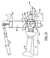
- FIGURES 10 and 11 PTO connection module 50 is shown with the implement in the engaged and latched position.
- torque coupler 60 is not rotationally aligned and thus cannot fully engage until one or both coupler portions rotate, illustrated as gap "F".
- Thrust bearing housing 102 is thus prevented from moving to the fully engaged (rearward) position.
- the force applied by PTO engagement springs 126 on the positioning tabs 104 urges the thrust bearing housing rearward in a direction urging engagement.
- the spring force on the positioning tabs 104 urges the thrust bearing housing 102 further rearward toward the fully engaged position, thereby fully engaging the torque coupler 60.
- This full engagement of torque coupler 60 is shown in FIGURE 11 wherein the torque coupler 60 is rotated for clarity.
- Gap "G,” as shown, is substantially zero meaning the coupler faces 72, 82 are in contact.
Landscapes
- Life Sciences & Earth Sciences (AREA)
- Engineering & Computer Science (AREA)
- Mechanical Engineering (AREA)
- Soil Sciences (AREA)
- Environmental Sciences (AREA)
- Zoology (AREA)
- Agricultural Machines (AREA)
Claims (5)
- Coupleur rapide (30) pour connecter un outil connectable par attelage (20) à un tracteur (10), ledit outil (20) comportant une broche supérieure d' attelage (21) et un couple de broches inférieures d' attelage (23), ledit coupleur rapide (30) comprenant :- une structure guidante (36) comportant une bride tournante (37) montée sur celle-ci pour permettre un mouvement entre une position engagée, dans laquelle ladite bride tournante (37) peut retenir une broche inférieure d' attelage associée (23), et une position desserrée dans laquelle la bride tournante (37) relâche une broche inférieure d' attelage associée (23) de ladite structure guidante (36),- un loquet (38) monté sur ladite structure guidante (36) amovible entre une première position dans laquelle il empêche le mouvement de ladite bride tournante (37) de ladite position verrouillée et une seconde position dans laquelle il autorise un tel mouvement, ledit loquet (38), lorsqu' il est en position verrouillée, permettant aux dites broches inférieures d' attelage (23) d' être engagées et retenues dans ladite structure guidante (36) de manière à permettre uniquement un mouvement généralement pivotant, et ledit loquet (38), lorsqu' il est en position déverrouillée, permettant un désengagement des dites broches inférieures d' attelage (23) en réponse à un mouvement de désengagement des dites broches inférieures d' attelage (23),- un mécanisme de verrouillage (41) pour déplacer sélectivement ledit loquet (38) entre des positions verrouillées et déverrouillées,- un arbre télescopique (18) ayant des première et seconde extrémités opposées, la première extrémité étant connectable au PTO du tracteur, et- un module de connexion PTO (50) connectable au dit coupleur rapide (30) et permettant un mouvement de rotation, axial et radial limité de ladite seconde extrémité de l' arbre télescopique (18), etcaractérisé en ce que le module de connexion PTO (50) comprend en plus un récepteur de broche d' alignement (74) pouvant fonctionner pour aligner ledit outil (20) et une face d' entraînement (72) opérationnelle pour transmettre le couple.
- Coupleur rapide (30) selon la revendication 1, caractérisé en ce que ledit mécanisme de verrouillage (41) comprend en plus un levier de verrouillage assisté par ressort (42), mobile entre une position verrouillée et déverrouillée.
- Coupleur rapide (30) selon la revendication 1 ou 2, caractérisé en ce que ladite bride tournante (37) a un profil semblable à une came et une structure de crochet pouvant fonctionner pour retenir les dites broches inférieures d' attelage (23) lorsqu' elle est en position engagée et permettre aux dites broches inférieures d' attelage (23) de se désengager lorsqu' elle est en position desserrée.
- Coupleur rapide (30) selon l'une quelconque des revendications précédentes, caractérisé en ce que ladite bride tournante (37) est opérationnelle pour être déplacée entre ladite position engagée et ladite position dégagée par le mouvement des dites broches d' attelage d' outil (23) pendant le désengagement de l' outil (20), et vice versa.
- Procédé de connexion d' un outil connectable par attelage à un tracteur comprenant les étapes suivantes :- pourvoir à un tracteur (10) comprenant un coupleur rapide (30) connecté au dit attelage à trois points du tracteur (12), ledit coupleur rapide (30) comprenant un crochet supérieur (35), une structure guidante (36), un loquet (38) et un mécanisme de verrouillage (41),- pourvoir à un mécanisme de verrouillage (41) apte à fonctionner pour sélectionner la position du dit loquet (38),- pourvoir à une structure guidante (36) logeant une bride tournante disposée de manière pivotante (37),- pourvoir à un outil (20) ayant une broche d' attelage supérieure (21) et un couple de broches inférieures d' attelage (23),- positionner le tracteur à proximité de l' outil de telle sorte que le coupleur rapide soit adjacent aux broches d' attelage de l' outil,- positionner le mécanisme de verrouillage (41) en ladite position verrouillée,- engager la broche d' attelage supérieure (21) dans le crochet supérieur (35),- soulever le coupleur rapide (30) en faisant pivoter ledit outil (20) autour de ladite broche supérieure (21), en déplaçant par cela les dites broches inférieures d' attelage (23) dans un engagement avec la dite structure guidante (36), et- déplacer ladite bride tournante (37) d' une position desserrée vers une position engagée et retenir ledit outil (20), etcaractérisé en ce que le procédé comprend en plus les étapes complémentaires consistant à :- pourvoir à un module de connexion PTO (50) à auto-alignement connecté audit coupleur rapide (30),- pourvoir à un élément récepteur (80) connecté au dit outil (20), et- soulever ledit coupleur rapide (30) en faisant pivoter (20) l' outil autour de ladite broche supérieure (21), en déplaçant par ce moyen les dites broches inférieures d' attelage (23) dans un engagement avec ladite structure guidante (36) et déplacer ledit élément récepteur (80) pour l' engager avec ledit module de connexion PTO (50).
Applications Claiming Priority (1)
| Application Number | Priority Date | Filing Date | Title |
|---|---|---|---|
| US11/610,931 US7690439B2 (en) | 2006-12-14 | 2006-12-14 | Automatic latch for three point hitch quick coupler and PTO connection module |
Publications (2)
| Publication Number | Publication Date |
|---|---|
| EP1932411A1 EP1932411A1 (fr) | 2008-06-18 |
| EP1932411B1 true EP1932411B1 (fr) | 2010-04-07 |
Family
ID=39047566
Family Applications (1)
| Application Number | Title | Priority Date | Filing Date |
|---|---|---|---|
| EP07123261A Not-in-force EP1932411B1 (fr) | 2006-12-14 | 2007-12-14 | Verrou automatique pour couplage rapide de crochet en trois points et module de connexion PTO |
Country Status (4)
| Country | Link |
|---|---|
| US (1) | US7690439B2 (fr) |
| EP (1) | EP1932411B1 (fr) |
| AT (1) | ATE463153T1 (fr) |
| DE (1) | DE602007005756D1 (fr) |
Cited By (7)
| Publication number | Priority date | Publication date | Assignee | Title |
|---|---|---|---|---|
| US10015922B2 (en) | 2014-03-03 | 2018-07-10 | Tracto-Lock | Device for hitching a tool, such as an agricultural tool, onto a hauling system of a vehicle such as an agricultural tractor |
| US10670479B2 (en) | 2018-02-27 | 2020-06-02 | Methode Electronics, Inc. | Towing systems and methods using magnetic field sensing |
| US10696109B2 (en) | 2017-03-22 | 2020-06-30 | Methode Electronics Malta Ltd. | Magnetolastic based sensor assembly |
| US11084342B2 (en) | 2018-02-27 | 2021-08-10 | Methode Electronics, Inc. | Towing systems and methods using magnetic field sensing |
| US11135882B2 (en) | 2018-02-27 | 2021-10-05 | Methode Electronics, Inc. | Towing systems and methods using magnetic field sensing |
| US11221262B2 (en) | 2018-02-27 | 2022-01-11 | Methode Electronics, Inc. | Towing systems and methods using magnetic field sensing |
| US11491832B2 (en) | 2018-02-27 | 2022-11-08 | Methode Electronics, Inc. | Towing systems and methods using magnetic field sensing |
Families Citing this family (32)
| Publication number | Priority date | Publication date | Assignee | Title |
|---|---|---|---|---|
| DK1852555T3 (da) * | 2006-05-02 | 2012-10-08 | Kinshofer Gmbh | Sikkerhedslåseindretning til en lynkobling |
| DE102007043032B4 (de) | 2007-09-11 | 2009-07-02 | Gkn Walterscheid Gmbh | Vorrichtung zum Kuppeln einer Gelenkwelle mit einer Zapfwelle eines Traktors |
| KR101007323B1 (ko) * | 2008-12-02 | 2011-01-13 | 주식회사 세웅 | 트랙터용 작업기의 연결 장치 |
| DE102010028605A1 (de) * | 2010-05-05 | 2011-11-10 | Deere & Company | Antriebsanordnung für einen Erntevorsatz einer Erntemaschine |
| US8555995B2 (en) | 2010-12-03 | 2013-10-15 | Jerry Harris | Three-point front hitch mountable to the frame of an agricultural tractor |
| US8763715B2 (en) * | 2011-05-11 | 2014-07-01 | Ralph L. Osgood, Inc. | Quick-connect plow hitch |
| CA2787433A1 (fr) * | 2011-08-30 | 2013-02-28 | Jean Despres | Systeme et methode de connexion pour un accessoire de vehicule, comme une charrue |
| US9033074B1 (en) * | 2012-11-19 | 2015-05-19 | Chris Gates | Coupler with movable shaft |
| WO2014125466A1 (fr) * | 2013-02-13 | 2014-08-21 | Cruikshank Trevor Glenn | Attelage |
| US9220188B2 (en) * | 2013-08-19 | 2015-12-29 | Forage Innovations B.V. | Individually articulating automatic transport locks for folding implements |
| FR3009921B1 (fr) * | 2013-09-03 | 2016-05-27 | Kamf | Dispositif combine d'andainage et de pressage en balles, notamment pour le foin |
| DE102013110688B4 (de) | 2013-09-26 | 2019-05-09 | Claas Saulgau Gmbh | Vorrichtung und Verfahren zum Ankoppeln eines Erntevorsatzes an eine Erntemaschine |
| WO2015069251A1 (fr) * | 2013-11-07 | 2015-05-14 | Volvo Construction Equipment Ab | Dispositif d'accouplement pour engin de chantier |
| KR101722298B1 (ko) * | 2014-07-23 | 2017-04-11 | 이리중 | 작업기 연결장치 |
| KR101656932B1 (ko) * | 2014-07-23 | 2016-09-12 | 이리중 | 동력전달이 가능한 작업기 연결장치 |
| KR101760173B1 (ko) * | 2015-03-11 | 2017-07-20 | 이리중 | 위치 가변형 작업기 결속구를 구비한 트랙터 연결장치 |
| EP3138373A1 (fr) * | 2015-09-02 | 2017-03-08 | O'Connor, John | Appareil d'attelage |
| FR3042094B1 (fr) | 2015-10-09 | 2018-03-09 | Tracto-Lock | Procede et dispositif d'attelage d'un outil agricole sur un systeme de relevage trois points d'un tracteur agricole |
| US9750185B2 (en) * | 2015-11-10 | 2017-09-05 | Cnh Industrial America Llc | Latching device for header mounting apparatus |
| US9775276B2 (en) * | 2016-02-26 | 2017-10-03 | Yanmar Co., Ltd. | Working vehicle |
| CN106856697A (zh) * | 2017-01-10 | 2017-06-20 | 江苏大学 | 拖拉机悬挂快速挂接装置 |
| US10899182B2 (en) | 2017-08-15 | 2021-01-26 | Nathan Lasater | Tractor hitch |
| US11477930B2 (en) * | 2018-10-01 | 2022-10-25 | Vermeer Manufacturing Company | Three-point hitch mount systems |
| CA3078204C (fr) | 2019-04-19 | 2022-11-08 | Great Plains Manufacturing, Inc. | Ensemble de fixation pour materiel agricole |
| CN110214491B (zh) * | 2019-06-13 | 2024-07-30 | 中国农业机械化科学研究院 | 多功能高位快速挂接装置及具有该装置的高地隙喷雾机 |
| DE102019116389A1 (de) * | 2019-06-17 | 2020-12-17 | Grimme Landmaschinenfabrik Gmbh & Co. Kg | Tragwerk für die Verbindung zweier landwirtschaftlicher Anbaugeräte mit einem Schlepper sowie landwirtschaftliches Anbaugerät |
| FR3098082B1 (fr) * | 2019-07-05 | 2021-09-03 | Hubert Defrancq | Dispositif d’attelage pour engin agricole |
| KR102357398B1 (ko) * | 2019-12-19 | 2022-01-27 | 이재영 | 승용 관리기용 작업기 연결장치 |
| US12426543B2 (en) * | 2020-11-11 | 2025-09-30 | Techtronic Cordless Gp | Lawn mowers, detachable mower decks, and methods associated therewith |
| CA3210147A1 (fr) | 2021-03-02 | 2022-09-09 | Thomas G. Lykken | Chargeur dote d'un moteur auxiliaire sur une interface de fixation et fixation associee |
| USD978203S1 (en) | 2021-05-27 | 2023-02-14 | Cnh Industrial America Llc | Quick coupler for a three-point hitch |
| US12538857B1 (en) * | 2022-09-14 | 2026-02-03 | Abi Attachments, Inc. | Self-aligning, engagement-biased hitch apparatuses, methods, and systems |
Family Cites Families (38)
| Publication number | Priority date | Publication date | Assignee | Title |
|---|---|---|---|---|
| US1060441A (en) * | 1912-08-01 | 1913-04-29 | Daniel M Engel | Coupling for agricultural machinery. |
| US1437836A (en) * | 1919-04-30 | 1922-12-05 | Ohio Trailer Company | Automobile trailer coupling |
| US2381633A (en) * | 1941-10-15 | 1945-08-07 | Young Leonard Weare | Lock and fastening device |
| US2429761A (en) * | 1946-06-17 | 1947-10-28 | Ketel Henry | Pintle hook |
| US2636568A (en) * | 1949-10-31 | 1953-04-28 | Rapid Motormaher A G | Coupling means for power take-offs |
| US2559962A (en) * | 1950-03-22 | 1951-07-10 | Hudson Neal | Vehicular coupler |
| US2979137A (en) * | 1958-03-17 | 1961-04-11 | Deere & Co | Tractor-pickup hitch |
| US3078106A (en) * | 1960-07-18 | 1963-02-19 | Case Co J I | Implement connecting means |
| US3007535A (en) * | 1960-10-31 | 1961-11-07 | Deere & Co | Implement attaching means |
| NL275314A (fr) * | 1961-02-28 | |||
| US3283840A (en) * | 1963-06-18 | 1966-11-08 | Guy E Lane | Automatically engageable power take-off coupling |
| GB1222991A (en) * | 1967-04-20 | 1971-02-17 | Harley Patents Int | Latch mechanism |
| US3512804A (en) * | 1967-12-15 | 1970-05-19 | Arnold Siegert | Lock and hitch assembly |
| US4176727A (en) * | 1975-03-19 | 1979-12-04 | Societe Fiat France, S.A. | Devices for automatically coupling implements to self-propelled articles |
| FR2304268A1 (fr) * | 1975-03-19 | 1976-10-15 | Fiat France Sa | Dispositif d'accouplement automatique des outils a l'avant et a l'arriere d'un vehicule automoteur |
| US4074639A (en) * | 1977-02-10 | 1978-02-21 | Chromalloy American Corporation | Trailer for farm tractors with driven member powered by p.t.o. |
| US4158996A (en) * | 1977-09-12 | 1979-06-26 | Pullman Inc. | Locking arrangement for hopper car doors |
| US4433767A (en) * | 1979-07-16 | 1984-02-28 | Thor Charles C | Power transmission mechanism |
| US4492292A (en) * | 1982-08-06 | 1985-01-08 | Thor Charles C | Coupling system for power take-off shafts |
| JPH078161B2 (ja) * | 1986-07-16 | 1995-02-01 | ヤンマーディーゼル株式会社 | トラクタ−の作業機装着装置 |
| JPS63148905A (ja) * | 1986-12-13 | 1988-06-21 | 株式会社クボタ | トラクタと作業機の連結装置 |
| GB2202125B (en) * | 1987-03-19 | 1990-11-14 | Kubota Ltd | Device for connecting working implement to tractor |
| GB2209264B (en) * | 1987-09-03 | 1992-01-02 | Kubota Ltd | Device for connecting work machine to tractor |
| DE3812198A1 (de) * | 1988-04-13 | 1989-10-26 | Walterscheid Gmbh Jean | Dreipunktanbauvorrichtung |
| US4968054A (en) * | 1988-04-27 | 1990-11-06 | Georg Fischer Ag | Coupling |
| US5031927A (en) * | 1989-07-14 | 1991-07-16 | Frenette Albert E | Semi-automatic attach device for mounting snowplows |
| US5244047A (en) * | 1991-08-05 | 1993-09-14 | Arthur H. Groover | Apparatus for coupling implements to a farm tractor |
| US5257796A (en) | 1992-03-26 | 1993-11-02 | Holland Hitch Company | Integrated cam lever/handle lock fifth wheel |
| US5240274A (en) * | 1992-03-27 | 1993-08-31 | Premier Equipment, Inc. | Handle mechanism for trailer coupling |
| US5303790A (en) * | 1992-06-02 | 1994-04-19 | Coleman Lyle W | Quick attaching power take off |
| SE9303291L (sv) * | 1993-10-08 | 1994-09-26 | Lars Englund | Kopplingsanordning vid traktor |
| CA2130931A1 (fr) | 1993-08-23 | 1995-02-24 | Glenn Solberg | Dispositif de raccordement extensible muni de mecanismes de verrouillage |
| US5984019A (en) | 1995-01-30 | 1999-11-16 | Hund; George A. | Hitching device for attachment to a tractor |
| US5667330A (en) * | 1995-11-28 | 1997-09-16 | Case Corporation | Quick-connect mechanism for releasably retaining a power take-off shaft within an output shaft hub |
| US6155616A (en) | 1997-06-16 | 2000-12-05 | Randall C. Hansen | Locking mechanism and closure assembly including same |
| DE10324520B4 (de) * | 2003-05-28 | 2006-01-26 | Gkn Walterscheid Gmbh | Kuppelvorrichtung |
| US7278502B2 (en) * | 2004-09-15 | 2007-10-09 | Deere & Company | Implement and power take off attachment system |
| FR2878402B1 (fr) * | 2004-11-30 | 2008-05-23 | Kuhn Audureau Sa Sa | Machine avec un dispositif d'accouplement au systeme d'attelage trois points d'un tracteur |
-
2006
- 2006-12-14 US US11/610,931 patent/US7690439B2/en not_active Expired - Fee Related
-
2007
- 2007-12-14 DE DE602007005756T patent/DE602007005756D1/de active Active
- 2007-12-14 EP EP07123261A patent/EP1932411B1/fr not_active Not-in-force
- 2007-12-14 AT AT07123261T patent/ATE463153T1/de not_active IP Right Cessation
Cited By (8)
| Publication number | Priority date | Publication date | Assignee | Title |
|---|---|---|---|---|
| US10015922B2 (en) | 2014-03-03 | 2018-07-10 | Tracto-Lock | Device for hitching a tool, such as an agricultural tool, onto a hauling system of a vehicle such as an agricultural tractor |
| US10696109B2 (en) | 2017-03-22 | 2020-06-30 | Methode Electronics Malta Ltd. | Magnetolastic based sensor assembly |
| US10940726B2 (en) | 2017-03-22 | 2021-03-09 | Methode Electronics Malta Ltd. | Magnetoelastic based sensor assembly |
| US10670479B2 (en) | 2018-02-27 | 2020-06-02 | Methode Electronics, Inc. | Towing systems and methods using magnetic field sensing |
| US11084342B2 (en) | 2018-02-27 | 2021-08-10 | Methode Electronics, Inc. | Towing systems and methods using magnetic field sensing |
| US11135882B2 (en) | 2018-02-27 | 2021-10-05 | Methode Electronics, Inc. | Towing systems and methods using magnetic field sensing |
| US11221262B2 (en) | 2018-02-27 | 2022-01-11 | Methode Electronics, Inc. | Towing systems and methods using magnetic field sensing |
| US11491832B2 (en) | 2018-02-27 | 2022-11-08 | Methode Electronics, Inc. | Towing systems and methods using magnetic field sensing |
Also Published As
| Publication number | Publication date |
|---|---|
| EP1932411A1 (fr) | 2008-06-18 |
| US7690439B2 (en) | 2010-04-06 |
| DE602007005756D1 (de) | 2010-05-20 |
| US20080142231A1 (en) | 2008-06-19 |
| ATE463153T1 (de) | 2010-04-15 |
Similar Documents
| Publication | Publication Date | Title |
|---|---|---|
| EP1932411A1 (fr) | Verrou automatique pour couplage rapide de crochet en trois points et module de connexion PTO | |
| EP1925195B1 (fr) | Module PTO de connexion de levier pour couplage rapide de crochet en trois points | |
| US10327383B2 (en) | Mid-mount mower with power transmission coupling | |
| EP1884151B1 (fr) | Procédé et dispositif pour coupler automatiquement une interface d'alimentation combinée et un en-tête combiné | |
| CA2958511C (fr) | Dispositifs d'installation d'attache a deux points | |
| EP2042016B1 (fr) | Mécanisme de connexion automatique pour outil en position centrale | |
| EP0316900B1 (fr) | Attelage | |
| EP2042013B1 (fr) | Couplage de PTO pour connexion automatique | |
| US4887680A (en) | Device for connecting work machine to tractor | |
| US4799563A (en) | Device for mounting an implement on a tractor | |
| JPH0370444B2 (fr) | ||
| GB2133963A (en) | Tractor-implement connections | |
| CA1294480C (fr) | Dispositif de couplage d'instruments de travail a un tracteur | |
| US12207584B2 (en) | Power take-off (PTO) connection mechanism for mid mounted tools of a utility vehicle | |
| US4792006A (en) | Drive shaft coupling | |
| JP3535883B2 (ja) | 作業機連結装置 | |
| JPH0515204A (ja) | トラクタ作業機の連結装置 | |
| JPS63230001A (ja) | トラクタと作業機の連結装置 | |
| JP3284598B2 (ja) | トラクタの作業機連結装置 | |
| JPH0789771B2 (ja) | トラクタへの作業機装着装置 | |
| JPH0370441B2 (fr) | ||
| JPS63192302A (ja) | トラクタと作業機の連結装置 | |
| JPH0642411Y2 (ja) | 作業機連結装置 | |
| JPS63230004A (ja) | トラクタと作業機の連結装置 | |
| JPH071929Y2 (ja) | トラクタと作業機の連結装置 |
Legal Events
| Date | Code | Title | Description |
|---|---|---|---|
| PUAI | Public reference made under article 153(3) epc to a published international application that has entered the european phase |
Free format text: ORIGINAL CODE: 0009012 |
|
| AK | Designated contracting states |
Kind code of ref document: A1 Designated state(s): AT BE BG CH CY CZ DE DK EE ES FI FR GB GR HU IE IS IT LI LT LU LV MC MT NL PL PT RO SE SI SK TR |
|
| AX | Request for extension of the european patent |
Extension state: AL BA HR MK RS |
|
| 17P | Request for examination filed |
Effective date: 20081218 |
|
| AKX | Designation fees paid |
Designated state(s): AT BE BG CH CY CZ DE DK EE ES FI FR GB GR HU IE IS IT LI LT LU LV MC MT NL PL PT RO SE SI SK TR |
|
| 17Q | First examination report despatched |
Effective date: 20090202 |
|
| GRAP | Despatch of communication of intention to grant a patent |
Free format text: ORIGINAL CODE: EPIDOSNIGR1 |
|
| GRAS | Grant fee paid |
Free format text: ORIGINAL CODE: EPIDOSNIGR3 |
|
| GRAA | (expected) grant |
Free format text: ORIGINAL CODE: 0009210 |
|
| AK | Designated contracting states |
Kind code of ref document: B1 Designated state(s): AT BE BG CH CY CZ DE DK EE ES FI FR GB GR HU IE IS IT LI LT LU LV MC MT NL PL PT RO SE SI SK TR |
|
| REG | Reference to a national code |
Ref country code: GB Ref legal event code: FG4D |
|
| REG | Reference to a national code |
Ref country code: CH Ref legal event code: EP |
|
| REG | Reference to a national code |
Ref country code: IE Ref legal event code: FG4D |
|
| REF | Corresponds to: |
Ref document number: 602007005756 Country of ref document: DE Date of ref document: 20100520 Kind code of ref document: P |
|
| REG | Reference to a national code |
Ref country code: NL Ref legal event code: VDEP Effective date: 20100407 |
|
| PG25 | Lapsed in a contracting state [announced via postgrant information from national office to epo] |
Ref country code: SI Free format text: LAPSE BECAUSE OF FAILURE TO SUBMIT A TRANSLATION OF THE DESCRIPTION OR TO PAY THE FEE WITHIN THE PRESCRIBED TIME-LIMIT Effective date: 20100407 |
|
| LTIE | Lt: invalidation of european patent or patent extension |
Effective date: 20100407 |
|
| PG25 | Lapsed in a contracting state [announced via postgrant information from national office to epo] |
Ref country code: SE Free format text: LAPSE BECAUSE OF FAILURE TO SUBMIT A TRANSLATION OF THE DESCRIPTION OR TO PAY THE FEE WITHIN THE PRESCRIBED TIME-LIMIT Effective date: 20100407 Ref country code: ES Free format text: LAPSE BECAUSE OF FAILURE TO SUBMIT A TRANSLATION OF THE DESCRIPTION OR TO PAY THE FEE WITHIN THE PRESCRIBED TIME-LIMIT Effective date: 20100718 Ref country code: LT Free format text: LAPSE BECAUSE OF FAILURE TO SUBMIT A TRANSLATION OF THE DESCRIPTION OR TO PAY THE FEE WITHIN THE PRESCRIBED TIME-LIMIT Effective date: 20100407 Ref country code: NL Free format text: LAPSE BECAUSE OF FAILURE TO SUBMIT A TRANSLATION OF THE DESCRIPTION OR TO PAY THE FEE WITHIN THE PRESCRIBED TIME-LIMIT Effective date: 20100407 |
|
| PG25 | Lapsed in a contracting state [announced via postgrant information from national office to epo] |
Ref country code: LV Free format text: LAPSE BECAUSE OF FAILURE TO SUBMIT A TRANSLATION OF THE DESCRIPTION OR TO PAY THE FEE WITHIN THE PRESCRIBED TIME-LIMIT Effective date: 20100407 Ref country code: AT Free format text: LAPSE BECAUSE OF FAILURE TO SUBMIT A TRANSLATION OF THE DESCRIPTION OR TO PAY THE FEE WITHIN THE PRESCRIBED TIME-LIMIT Effective date: 20100407 Ref country code: FI Free format text: LAPSE BECAUSE OF FAILURE TO SUBMIT A TRANSLATION OF THE DESCRIPTION OR TO PAY THE FEE WITHIN THE PRESCRIBED TIME-LIMIT Effective date: 20100407 Ref country code: IS Free format text: LAPSE BECAUSE OF FAILURE TO SUBMIT A TRANSLATION OF THE DESCRIPTION OR TO PAY THE FEE WITHIN THE PRESCRIBED TIME-LIMIT Effective date: 20100807 |
|
| PG25 | Lapsed in a contracting state [announced via postgrant information from national office to epo] |
Ref country code: CY Free format text: LAPSE BECAUSE OF FAILURE TO SUBMIT A TRANSLATION OF THE DESCRIPTION OR TO PAY THE FEE WITHIN THE PRESCRIBED TIME-LIMIT Effective date: 20100526 Ref country code: PL Free format text: LAPSE BECAUSE OF FAILURE TO SUBMIT A TRANSLATION OF THE DESCRIPTION OR TO PAY THE FEE WITHIN THE PRESCRIBED TIME-LIMIT Effective date: 20100407 |
|
| PG25 | Lapsed in a contracting state [announced via postgrant information from national office to epo] |
Ref country code: DK Free format text: LAPSE BECAUSE OF FAILURE TO SUBMIT A TRANSLATION OF THE DESCRIPTION OR TO PAY THE FEE WITHIN THE PRESCRIBED TIME-LIMIT Effective date: 20100407 Ref country code: EE Free format text: LAPSE BECAUSE OF FAILURE TO SUBMIT A TRANSLATION OF THE DESCRIPTION OR TO PAY THE FEE WITHIN THE PRESCRIBED TIME-LIMIT Effective date: 20100407 Ref country code: PT Free format text: LAPSE BECAUSE OF FAILURE TO SUBMIT A TRANSLATION OF THE DESCRIPTION OR TO PAY THE FEE WITHIN THE PRESCRIBED TIME-LIMIT Effective date: 20100809 |
|
| PLBE | No opposition filed within time limit |
Free format text: ORIGINAL CODE: 0009261 |
|
| STAA | Information on the status of an ep patent application or granted ep patent |
Free format text: STATUS: NO OPPOSITION FILED WITHIN TIME LIMIT |
|
| PG25 | Lapsed in a contracting state [announced via postgrant information from national office to epo] |
Ref country code: RO Free format text: LAPSE BECAUSE OF FAILURE TO SUBMIT A TRANSLATION OF THE DESCRIPTION OR TO PAY THE FEE WITHIN THE PRESCRIBED TIME-LIMIT Effective date: 20100407 Ref country code: SK Free format text: LAPSE BECAUSE OF FAILURE TO SUBMIT A TRANSLATION OF THE DESCRIPTION OR TO PAY THE FEE WITHIN THE PRESCRIBED TIME-LIMIT Effective date: 20100407 Ref country code: BE Free format text: LAPSE BECAUSE OF FAILURE TO SUBMIT A TRANSLATION OF THE DESCRIPTION OR TO PAY THE FEE WITHIN THE PRESCRIBED TIME-LIMIT Effective date: 20100407 Ref country code: CZ Free format text: LAPSE BECAUSE OF FAILURE TO SUBMIT A TRANSLATION OF THE DESCRIPTION OR TO PAY THE FEE WITHIN THE PRESCRIBED TIME-LIMIT Effective date: 20100407 |
|
| 26N | No opposition filed |
Effective date: 20110110 |
|
| PG25 | Lapsed in a contracting state [announced via postgrant information from national office to epo] |
Ref country code: GR Free format text: LAPSE BECAUSE OF FAILURE TO SUBMIT A TRANSLATION OF THE DESCRIPTION OR TO PAY THE FEE WITHIN THE PRESCRIBED TIME-LIMIT Effective date: 20100708 |
|
| PG25 | Lapsed in a contracting state [announced via postgrant information from national office to epo] |
Ref country code: MC Free format text: LAPSE BECAUSE OF NON-PAYMENT OF DUE FEES Effective date: 20101231 |
|
| PG25 | Lapsed in a contracting state [announced via postgrant information from national office to epo] |
Ref country code: IE Free format text: LAPSE BECAUSE OF NON-PAYMENT OF DUE FEES Effective date: 20101214 |
|
| PG25 | Lapsed in a contracting state [announced via postgrant information from national office to epo] |
Ref country code: MT Free format text: LAPSE BECAUSE OF FAILURE TO SUBMIT A TRANSLATION OF THE DESCRIPTION OR TO PAY THE FEE WITHIN THE PRESCRIBED TIME-LIMIT Effective date: 20100407 Ref country code: IT Free format text: LAPSE BECAUSE OF NON-PAYMENT OF DUE FEES Effective date: 20101214 |
|
| REG | Reference to a national code |
Ref country code: CH Ref legal event code: PL |
|
| PG25 | Lapsed in a contracting state [announced via postgrant information from national office to epo] |
Ref country code: HU Free format text: LAPSE BECAUSE OF FAILURE TO SUBMIT A TRANSLATION OF THE DESCRIPTION OR TO PAY THE FEE WITHIN THE PRESCRIBED TIME-LIMIT Effective date: 20101008 Ref country code: LU Free format text: LAPSE BECAUSE OF NON-PAYMENT OF DUE FEES Effective date: 20101214 Ref country code: BG Free format text: LAPSE BECAUSE OF FAILURE TO SUBMIT A TRANSLATION OF THE DESCRIPTION OR TO PAY THE FEE WITHIN THE PRESCRIBED TIME-LIMIT Effective date: 20100407 |
|
| PG25 | Lapsed in a contracting state [announced via postgrant information from national office to epo] |
Ref country code: TR Free format text: LAPSE BECAUSE OF FAILURE TO SUBMIT A TRANSLATION OF THE DESCRIPTION OR TO PAY THE FEE WITHIN THE PRESCRIBED TIME-LIMIT Effective date: 20100407 Ref country code: CH Free format text: LAPSE BECAUSE OF NON-PAYMENT OF DUE FEES Effective date: 20111231 Ref country code: LI Free format text: LAPSE BECAUSE OF NON-PAYMENT OF DUE FEES Effective date: 20111231 |
|
| PG25 | Lapsed in a contracting state [announced via postgrant information from national office to epo] |
Ref country code: BG Free format text: LAPSE BECAUSE OF FAILURE TO SUBMIT A TRANSLATION OF THE DESCRIPTION OR TO PAY THE FEE WITHIN THE PRESCRIBED TIME-LIMIT Effective date: 20100707 |
|
| REG | Reference to a national code |
Ref country code: DE Ref legal event code: R082 Ref document number: 602007005756 Country of ref document: DE Representative=s name: PATENTANWAELTE WALLACH, KOCH & PARTNER, DE |
|
| REG | Reference to a national code |
Ref country code: DE Ref legal event code: R082 Ref document number: 602007005756 Country of ref document: DE Representative=s name: PATENTANWAELTE WALLACH, KOCH & PARTNER, DE Effective date: 20140623 Ref country code: DE Ref legal event code: R081 Ref document number: 602007005756 Country of ref document: DE Owner name: CNH INDUSTRIAL ITALIA S.P.A., IT Free format text: FORMER OWNER: CNH ITALIA S.P.A., MODENA, IT Effective date: 20140623 Ref country code: DE Ref legal event code: R082 Ref document number: 602007005756 Country of ref document: DE Representative=s name: PATENTANWAELTE WALLACH, KOCH, DR. HAIBACH, FEL, DE Effective date: 20140623 |
|
| REG | Reference to a national code |
Ref country code: FR Ref legal event code: CD Owner name: CNH INDUSTRIAL ITALIA S.P.A. Effective date: 20150313 |
|
| REG | Reference to a national code |
Ref country code: FR Ref legal event code: PLFP Year of fee payment: 9 |
|
| REG | Reference to a national code |
Ref country code: FR Ref legal event code: PLFP Year of fee payment: 10 |
|
| REG | Reference to a national code |
Ref country code: FR Ref legal event code: PLFP Year of fee payment: 11 |
|
| REG | Reference to a national code |
Ref country code: FR Ref legal event code: PLFP Year of fee payment: 12 |
|
| PGFP | Annual fee paid to national office [announced via postgrant information from national office to epo] |
Ref country code: GB Payment date: 20191220 Year of fee payment: 13 |
|
| REG | Reference to a national code |
Ref country code: DE Ref legal event code: R082 Ref document number: 602007005756 Country of ref document: DE Representative=s name: MEISSNER BOLTE PATENTANWAELTE RECHTSANWAELTE P, DE |
|
| REG | Reference to a national code |
Ref country code: DE Ref legal event code: R084 Ref document number: 602007005756 Country of ref document: DE |
|
| GBPC | Gb: european patent ceased through non-payment of renewal fee |
Effective date: 20201214 |
|
| PG25 | Lapsed in a contracting state [announced via postgrant information from national office to epo] |
Ref country code: GB Free format text: LAPSE BECAUSE OF NON-PAYMENT OF DUE FEES Effective date: 20201214 |
|
| PGFP | Annual fee paid to national office [announced via postgrant information from national office to epo] |
Ref country code: IT Payment date: 20231127 Year of fee payment: 17 Ref country code: FR Payment date: 20231220 Year of fee payment: 17 |
|
| PGFP | Annual fee paid to national office [announced via postgrant information from national office to epo] |
Ref country code: DE Payment date: 20231221 Year of fee payment: 17 |
|
| REG | Reference to a national code |
Ref country code: DE Ref legal event code: R119 Ref document number: 602007005756 Country of ref document: DE |
|
| PG25 | Lapsed in a contracting state [announced via postgrant information from national office to epo] |
Ref country code: DE Free format text: LAPSE BECAUSE OF NON-PAYMENT OF DUE FEES Effective date: 20250701 |
|
| PG25 | Lapsed in a contracting state [announced via postgrant information from national office to epo] |
Ref country code: IT Free format text: LAPSE BECAUSE OF NON-PAYMENT OF DUE FEES Effective date: 20241214 |
|
| PG25 | Lapsed in a contracting state [announced via postgrant information from national office to epo] |
Ref country code: FR Free format text: LAPSE BECAUSE OF NON-PAYMENT OF DUE FEES Effective date: 20241231 |