EP1932791B1 - Procédé destiné à la mesure de l'effort de traction d'une bande déroulante - Google Patents
Procédé destiné à la mesure de l'effort de traction d'une bande déroulante Download PDFInfo
- Publication number
- EP1932791B1 EP1932791B1 EP06026051A EP06026051A EP1932791B1 EP 1932791 B1 EP1932791 B1 EP 1932791B1 EP 06026051 A EP06026051 A EP 06026051A EP 06026051 A EP06026051 A EP 06026051A EP 1932791 B1 EP1932791 B1 EP 1932791B1
- Authority
- EP
- European Patent Office
- Prior art keywords
- wheatstone bridge
- sensor
- switch
- measuring
- tensile stress
- Prior art date
- Legal status (The legal status is an assumption and is not a legal conclusion. Google has not performed a legal analysis and makes no representation as to the accuracy of the status listed.)
- Active
Links
Images


Classifications
-
- B—PERFORMING OPERATIONS; TRANSPORTING
- B65—CONVEYING; PACKING; STORING; HANDLING THIN OR FILAMENTARY MATERIAL
- B65H—HANDLING THIN OR FILAMENTARY MATERIAL, e.g. SHEETS, WEBS, CABLES
- B65H23/00—Registering, tensioning, smoothing or guiding webs
- B65H23/04—Registering, tensioning, smoothing or guiding webs longitudinally
- B65H23/18—Registering, tensioning, smoothing or guiding webs longitudinally by controlling or regulating the web-advancing mechanism, e.g. mechanism acting on the running web
- B65H23/188—Registering, tensioning, smoothing or guiding webs longitudinally by controlling or regulating the web-advancing mechanism, e.g. mechanism acting on the running web in connection with running-web
-
- B—PERFORMING OPERATIONS; TRANSPORTING
- B65—CONVEYING; PACKING; STORING; HANDLING THIN OR FILAMENTARY MATERIAL
- B65H—HANDLING THIN OR FILAMENTARY MATERIAL, e.g. SHEETS, WEBS, CABLES
- B65H26/00—Warning or safety devices, e.g. automatic fault detectors, stop-motions, for web-advancing mechanisms
- B65H26/02—Warning or safety devices, e.g. automatic fault detectors, stop-motions, for web-advancing mechanisms responsive to presence of irregularities in running webs
- B65H26/04—Warning or safety devices, e.g. automatic fault detectors, stop-motions, for web-advancing mechanisms responsive to presence of irregularities in running webs for variation in tension
Definitions
- the invention relates to a method for measuring the tension of a moving web according to the preamble of patent claim 1.
- a device for detecting the tension of a moving web which detects the bearing force of a web deflecting the web.
- this device has two double bending beams, which are equipped with force transducers in the form of strain gauges. These strain gauges are connected in the form of a Wheatstone bridge in order to achieve the lowest possible temperature dependence and drift of the sensor.
- This sensor has been well proven in practice and forms the starting point of the present invention.
- a disadvantage of this known sensor has been found that in case of failure of the strain gauges, for example by breakage or short circuit, the entire sensor provides nonsensical values, which are then interpreted accordingly by subsequent units.
- the sensor is included in the control loop of a web tension control, for example, it may happen, depending on the type of failure, that the control completely eliminates the web tension or greatly overstretches the running web. In the simplest case, this can lead to a web break if the web can no longer withstand the introduced tension or gets caught on machine parts due to the lack of tension. In particular, in the regulation of endless belts in paper machines, this can even lead to tearing out of rolls from their warehouses and thus a considerable risk to man and machine.
- the invention has for its object to provide a method for measuring the tension of a moving web of the type mentioned, which also detect the failure of electronic components and can respond accordingly.
- the method according to claim 1 is used for measuring the tension of a moving web with a sensor. It does not matter whether the train is self-contained or continuous. Also, the material of the running track plays no role in the application of this method.
- the sensor has a Wheatstone bridge containing at least one force transducer. As load cell different sensor principles come in Question, which are able to convert a force or a mechanical deformation into an electrical signal. Strain gauges are preferably used as force sensors, which are mounted on a mechanical component - for example, a double bending beam - which is deformed by the action of the force to be measured. Basically, it is sufficient to form only a resistance of the Wheatstone bridge as a force transducer.
- the diagonal voltage of the Wheatstone bridge is a measure of the acting force.
- This diagonal voltage is amplified by an amplifier, which has the main task of keeping resistive loads from the Wheatstone bridge, which could distort the measurement result.
- the amplifier can also realize a voltage gain to bring the measurement signal to an easy-to-process voltage range.
- This amplifier outputs at its output from a signal which is proportional to a possibly to be taken into account offset the measured tensile stress and hereinafter referred to as Buchwoodssignal.
- the Wheatstone bridge is periodically loaded by at least one resistor during the stress by the tension of the moving web by means of at least one intermittently controlled switch.
- This load resistance detunes the Wheatstone bridge in a defined manner, wherein the effect of this load can be determined directly on the basis of a comparison of the tension signal with and without ohmic load.
- This test is carried out in the operation of the burdened by the web sensor, so that its functioning is checked in a timely manner.
- one of the force transducer of the loaded voltage divider should have an internal short circuit, it will be noted that the tensile signal does not change due to the stress of this voltage divider. The same applies to the case where the force transducer connected in series with the load resistor should be interrupted.
- the force transducer which is connected in parallel to the load resistor, should have an interruption, the result is a dependence of the tension signal on the load, but this is twice as high as in the case of the functioning sensor. This can be clearly checked from the dependence of the tension signal on the load, whether the sensor is still functional is. Within certain limits, drifts of the load cells can also be detected. According to the result of this test, the error signal is then activated or deactivated. The additional output of this error signal, subsequent components such as displays or controllers can be informed of the error of the measured signal. The subsequent components that are to evaluate the tension signal can then switch on receipt of an active error signal in a mode in which they no longer evaluate the tension signal, whereby damage to people or machines are avoided.
- both voltage dividing branches of the Wheatstone bridge have at least one force transducer
- the stress test of only one voltage divider for determining the functionality of the sensor is insufficient.
- both output lines of the Wheatstone bridge are loaded by at least one switch with at least one resistor. This allows the resistance values of all active elements of the Wheatstone bridge to be checked.
- an active error signal is output.
- the load on the Wheatstone bridge does not result in any change in the diagonal voltage compared to the unloaded case.
- the Wheatstone bridge if the Wheatstone bridge is fully functional, it will result in a detuning of the bridge symmetry, which leads to a change in the diagonal voltage. This change depends only on the resistance values of the Wheatstone bridge in relation to the resistance value of the load resistance and is therefore a known quantity.
- the range of values has been proven in accordance with claim 5.
- the upper limit of this value range must not be exceeded, otherwise a correctly functioning Wheatstone bridge would be detected as defective.
- the lower limit is given only for reasons of practicability, in particular to realize a sufficient signal-to-noise ratio of the diagonal voltage of the Wheatstone bridge. Otherwise, there is a risk that a defective Wheatstone bridge will be erroneously considered functional only due to noise.
- revision cycle For operation of the sensor, the use of a revision cycle has been proven according to claim 10.
- This revision cycle includes several measurement cycles of the sensor and is repeated periodically. In each revision cycle, at least one measuring cycle with a closed switch and at least one measuring cycle with an open switch is provided. This periodically outputs measured values and the entire sensor is also checked periodically.
- a short reaction time of the sensor is important. Often, an output of a measured value is no longer sufficient for every third measuring cycle in order to guarantee a clean regulation. In this case, it is favorable according to claim 12, if in each inspection cycle more measuring cycles are provided with an open switch than with the switch closed. Therefore, the sensor generates useful measurement results substantially at a time interval of its cycle time, wherein at certain predetermined intervals, an internal test of the sensor is made, so that then an isolated measurement cycle for the generation of the tensile signal fails. Of course, the last generated measured value can be stored and made available to the following components in order to bridge this failure.
- the load of the Wheatstone bridge results in an additional voltage swing in the diagonal voltage, which must be coped with by a subsequent amplifier and possibly analog-to-digital converter. This basically results in the analog-to-digital converter using part of its bit width for the load test. In case of a slight load of Wheatstone Bridge, this usually does not play a significant role. However, this results in a relatively large susceptibility to failure of the functional test of the Wheatstone bridge. If you want to use the entire dynamic range of the amplifier and the analog-to-digital converter with high significance of the functional test, it is favorable according to claim 14, when the load of the Wheatstone bridge and their supply voltage is changed. The supply voltage change is usually chosen so that it counteracts the effect of the load.
- the supply voltage is selected in the loaded and unloaded case so that in case of a functional Wheatstone bridge in about the same diagonal voltage occurs.
- the entire dynamic range of the amplifier and analog-to-digital converter can be used for the measurement task.
- a change in the diagonal voltage which can be detected by the analog-to-digital converter results in this case.
- the latter may possibly result in an overflow condition that is very easily detectable.
- An exact measurement of the voltage swing is not required in this case, since for this purpose, only the func tion is required efficiency as a yes-no decision.
- Wheatstone bridges each deliver diagonal voltages, which are evaluated via amplifiers and analog-to-digital converters. Both Wheatstone bridges are in the monitored as above. When an error signal occurs for one of the Wheatstone bridges, the generation of the tension signal is taken over by the other Wheatstone bridge.
- the same principle can be realized with more than two Wheatstone bridges. In this case, the individual Wheatstone bridges are preferably prioritized or their tension signal is averaged for better accuracy. Wheatstone bridges that show an active error signal are excluded from the calculation.
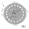
- FIG. 1 shows a sectional view through a Kraftmeßwalze 1, on which a web 2 is deflected.
- the web 2 exerts a force 3 on the Kraftmeßwalze 1, which depends only on the tension of the web 2 and the wrap around the Kraftmeßwalze 1.
- the force measuring roller 1 has a stationary body 4, which is connected via double bending beam 5 with a machine-fixed axis 6. Depending on the load of the force measuring roller 1 by the force 3, the double bending beams 5 are deformed more or less strongly S-shaped.
- force transducer 7 are applied, which are preferably formed by strain gauges. These force transducers are essentially ohmic resistors which change their resistance when bent.
- the force transducer 7 are mounted in the end regions of the double bending beam 5, where the curvature of the double bending beam 5 is strongest.
- the stationary body 4 is connected via a roller bearing 8 with a shell 9, which forms the outer contour of the force measuring roller 1. This shell 9 is detected directly by the web 2.
- the FIG. 2 shows a schematic diagram of a sensor 10, which detects the bearing force of the force measuring roller 1 and thus indirectly the tension of the web 2.
- the sensor 10 has a Wheatstone bridge 11, which is formed by two voltage dividers 12, 13.
- the voltage dividers 12, 13 are formed by the force sensors 7, which are applied to the double bending beam 5.
- the Wheatstone bridge 11 is supplied via a changeover switch 14 'optionally with a supply voltage 14 which is formed stable and low noise. From the Wheatstone bridge 11 go two output lines 15, 16 away, between which a diagonal voltage 17 drops. This diagonal voltage 17 is the actual measurement signal, which is obtained from the force transducers 7.
- the output lines 15, 16 are supplied to an amplifier 18, which is designed as a differential amplifier.
- the amplifier 18 has high-impedance inputs in order not to burden the Wheatstone bridge 11 as possible. In addition, the amplifier 18 can amplify the diagonal voltage 17 by a gain factor that allows easy evaluation of the diagonal voltage 17.
- the amplifier 18 is on the output side with an analog-to-digital converter 19 in operative connection, which generates from the output signal of the amplifier 18, a proportional thereto digital word.
- This digital word is supplied via a bus 20 to a processor 21 in which it is processed.
- the processor 21 can initiate a measurement cycle in the analog-to-digital converter 19 via a control line 22.
- the processor 21 receives the information via a signal line 23 that the measurement cycle of the analog-to-digital converter 19 has been completed and that a new data word is present on the bus 20.
- the two output lines 16, 17 can be loaded with a load resistor 26 via switches 24, 25.
- This load resistor 26 ensures a one-sided detuning of the Wheatstone bridge 11, so that a defined change in the diagonal voltage 17 is to be expected.
- This change in the diagonal voltage 17 is supplied via the amplifier 18 and the analog-to-digital converter 19 via the bus 20 to the processor 21, which applies corresponding mathematical operations on this data word.
- an error signal 28 is output.
- This error signal 28 indicates in the activated state that the Wheatstone bridge 11 is defective and therefore the output tension signal 27 is not usable.
- the processor 21 gives the following components a handshake signal 29 to synchronize with the data output of the processor 21.
- the processor 21 has two control outputs 30, 31, which ensure that the switches 24, 25 are closed only during a test cycle, the switches 24, 25 are not closed simultaneously, but only alternately , During a normal measuring operation, in which a new tension signal 27 is to be determined, the two switches 24, 25 are open.
- the supply voltage 14 of the Wheatstone bridge 11 can be switched by the processor 21.
- This switching causes a proportional change in the diagonal voltage 17, so that the voltage swing caused by the load becomes smaller. It is also thought to change the supply voltage of the Wheatstone bridge 11 so that it counteracts the load exactly. In this case, there is no load-dependent change in the diagonal voltage 17 when the Wheatstone bridge 11 is functional. In the case of a defective Wheatstone bridge 11, however, a characteristic voltage swing of the diagonal voltage 17 results in this case.
- FIG. 3 shows a flowchart for the operation of the processor 21.
- the two switches 24, 25 are opened and the error signal 28 is activated. This prevents a random value at the output 28 from being interpreted as a measured value.
- the switch 25 is first opened and a measuring cycle 34 is started.
- the measurement takes place in this case with unloaded Wheatstone bridge 11.
- the data obtained from the measurement cycle data stored in a variable Z 0 .
- FIG. 3 It would also be possible to start several measuring cycles 34 in succession and to output the measuring results if the error signal 28 is deactivated.
- the variables F 1 and F 2 are compared with predefined lower threshold values U and upper threshold values O. Only in the event that both variables F 1 and F 2 are within the band defined by the thresholds U and O, the sensor 10 is interpreted as functional and the value Z 0 is output. The value of Z 0 contains the measured value with no load Wheatstone bridge 11. In addition, the error signal 28 is reset in this case, to indicate that subsequent components of the output measurement value is reliable.
Landscapes
- Investigating Strength Of Materials By Application Of Mechanical Stress (AREA)
- Force Measurement Appropriate To Specific Purposes (AREA)
- Testing Of Short-Circuits, Discontinuities, Leakage, Or Incorrect Line Connections (AREA)
Claims (15)
- Procédé de mesure de la contrainte de traction dans une courroie (2) en déplacement à l'aide d'au moins un détecteur (10) qui présente au moins un pont de Wheatstone (11) qui contient au moins un détecteur de force (7) sur lequel agit la contrainte de traction de la courroie (2) en déplacement,
une tension diagonale (17) du ou des ponts de Wheatstone (11) étant amplifiée par un amplificateur (18) qui délivre un signal (Z0) de contrainte de traction,
caractérisé en ce que
le ou les ponts de Wheatstone (11) sont chargés périodiquement par au moins une résistance (26) au moyen d'un ou de commutateurs (24, 25) commandés de manière intermittente pendant que la courroie (2) en déplacement est sollicitée par la contrainte de traction, le bon fonctionnement du ou des détecteurs (10) étant déterminé à partir de l'action de la charge sur le signal (Z1) de contrainte de traction et étant délivré sous la forme d'un signal d'erreur (28). - Procédé selon la revendication 1, caractérisé en ce que les deux conducteurs de sortie (15, 16) du pont de Wheatstone (11) sont chargés par au moins une résistance (26) par l'intermédiaire d'au moins un commutateur (24, 25).
- Procédé selon la revendication 2, caractérisé en ce que les conducteurs de sortie (15, 16) du pont de Wheatstone (11) sont chargés en alternance par la ou les résistances (26).
- Procédé selon au moins l'une des revendications 1 à 3, caractérisé en ce que la différence (F1, F2) entre les signaux (Z0, Z1) de contrainte de traction sans et avec application d'une charge sur le pont de Wheatstone (11) est calculée et est comparée à une valeur limite inférieure (U) qui, lorsqu'elle n'est pas atteinte, entraîne l'émission d'un signal d'erreur (28) actif.
- Procédé selon la revendication 4, caractérisé en ce que la valeur limite inférieure (U) est située entre 0,05 fois et 0,5 fois la valeur :

UW représentant la tension d'alimentation du pont de Wheatstone (11), V le facteur d'amplification, RS la résistance de charge et RK la résistance du détecteur de force (7). - Procédé selon les revendications 4 ou 5, caractérisé en ce que la différence (F1, F2) est comparée à une valeur limite supérieure (0) qui, lorsqu'elle est dépassée, entraîne l'émission d'un signal d'erreur (28) actif.
- Procédé selon la revendication 6, caractérisé en ce que la valeur limite supérieure (0) est inférieure à 0,5 UW et inférieure à

UW représentant la tension d'alimentation du pont de Wheatstone (11), V le facteur d'amplification, RS la résistance de charge (26) et RK la résistance du détecteur de force (7). - Procédé selon au moins l'une des revendications 1 à 7, caractérisé en ce que le détecteur (10) délivre des valeurs (Z0) de contrainte de traction uniquement dans les cycles de mesure (34) au cours desquels le ou les commutateurs (24, 25) sont ouverts.
- Procédé selon au moins l'une des revendications 1 à 8, caractérisé en ce que la position du ou des commutateurs (24, 25) est synchronisée par rapport aux cycles de mesure (34, 35, 36) du détecteur (10).
- Procédé selon la revendication 9, caractérisé en ce qu'il prévoit un cycle de révision (33) qui comprend plusieurs cycles de mesure (34, 35, 36) du détecteur (10), au moins un cycle de mesure (35, 36) à commutateurs (24, 25) fermés et au moins un cycle de mesure (34) à commutateurs (24, 25) ouverts étant prévus dans chaque cycle de révision (33).
- Procédé selon la revendication 10, caractérisé en ce qu'au moins un cycle de mesure (35) dans lequel le commutateur (24) du premier conducteur de sortie (15) est fermé et au moins un cycle de mesure (36) dans lequel le commutateur (25) du deuxième conducteur de sortie (16) du pont de Wheatstone (11) est fermé sont prévus dans chaque cycle de révision (33).
- Procédé selon les revendications 10 ou 11, caractérisé en ce qu'un plus grand nombre de cycles de mesure (34) à commutateurs (24, 25) ouverts qu'à commutateurs (24, 25) fermés sont prévus dans chaque cycle de révision (33).
- Procédé selon au moins l'une des revendications 1 à 12, caractérisé en ce que la tension dans la courroie est régulée, le signal (27) de contrainte de traction délivré par le détecteur (10) étant utilisé comme valeur effective, la régulation étant bloquée lorsque le signal d'erreur (28) est actif.
- Procédé selon au moins l'une des revendications 1 à 13, caractérisé en ce que la tension d'alimentation (14) du pont de Wheatstone (11) est également modifiée en même temps que sa sollicitation.
- Procédé selon au moins l'une des revendications 1 à 14, caractérisé en ce qu'au moins deux ponts de Wheatstone (11) sont prévus, et en ce qu'en cas de signal d'erreur (28) d'un des ponts de Wheatstone (11), au moins l'un des autres ponts de Wheatstone (11) délivre le signal (Z0) de contrainte de traction.
Priority Applications (12)
| Application Number | Priority Date | Filing Date | Title |
|---|---|---|---|
| PL06026051T PL1932791T3 (pl) | 2006-12-15 | 2006-12-15 | Sposób pomiaru naprężenia rozciągającego w ruchomej taśmie |
| DE502006004817T DE502006004817D1 (de) | 2006-12-15 | 2006-12-15 | Verfahren zur Messung der Zugspannung einer laufenden Bahn |
| AT06026051T ATE442328T1 (de) | 2006-12-15 | 2006-12-15 | Verfahren zur messung der zugspannung einer laufenden bahn |
| ES06026051T ES2332663T3 (es) | 2006-12-15 | 2006-12-15 | Procedimiento para la medicion del esfuerzo de traccion de una banda movil. |
| EP06026051A EP1932791B1 (fr) | 2006-12-15 | 2006-12-15 | Procédé destiné à la mesure de l'effort de traction d'une bande déroulante |
| JP2009501975A JP2009531680A (ja) | 2006-12-15 | 2007-12-14 | 移動軌道の引張応力を測定する方法 |
| KR1020087022849A KR101050560B1 (ko) | 2006-12-15 | 2007-12-14 | 가동중인 웹의 인장응력 측정 방법 |
| CN2007800089615A CN101400593B (zh) | 2006-12-15 | 2007-12-14 | 用于对行进的网的拉伸应力进行测量的方法 |
| TW096147855A TWI366667B (en) | 2006-12-15 | 2007-12-14 | Method for measuring the tensile stress of a running web |
| US12/308,348 US7895907B2 (en) | 2006-12-15 | 2007-12-14 | Method of measuring the tensile stressing of a moving web |
| CA2642378A CA2642378C (fr) | 2006-12-15 | 2007-12-14 | Procede pour mesurer l'effort de tension d'une bande de materiau defilante |
| PCT/EP2007/010991 WO2008071436A1 (fr) | 2006-12-15 | 2007-12-14 | Procédé pour mesurer la tension d'une bande de matériau défilante |
Applications Claiming Priority (1)
| Application Number | Priority Date | Filing Date | Title |
|---|---|---|---|
| EP06026051A EP1932791B1 (fr) | 2006-12-15 | 2006-12-15 | Procédé destiné à la mesure de l'effort de traction d'une bande déroulante |
Publications (2)
| Publication Number | Publication Date |
|---|---|
| EP1932791A1 EP1932791A1 (fr) | 2008-06-18 |
| EP1932791B1 true EP1932791B1 (fr) | 2009-09-09 |
Family
ID=37943983
Family Applications (1)
| Application Number | Title | Priority Date | Filing Date |
|---|---|---|---|
| EP06026051A Active EP1932791B1 (fr) | 2006-12-15 | 2006-12-15 | Procédé destiné à la mesure de l'effort de traction d'une bande déroulante |
Country Status (12)
| Country | Link |
|---|---|
| US (1) | US7895907B2 (fr) |
| EP (1) | EP1932791B1 (fr) |
| JP (1) | JP2009531680A (fr) |
| KR (1) | KR101050560B1 (fr) |
| CN (1) | CN101400593B (fr) |
| AT (1) | ATE442328T1 (fr) |
| CA (1) | CA2642378C (fr) |
| DE (1) | DE502006004817D1 (fr) |
| ES (1) | ES2332663T3 (fr) |
| PL (1) | PL1932791T3 (fr) |
| TW (1) | TWI366667B (fr) |
| WO (1) | WO2008071436A1 (fr) |
Families Citing this family (5)
| Publication number | Priority date | Publication date | Assignee | Title |
|---|---|---|---|---|
| DE102005003632A1 (de) | 2005-01-20 | 2006-08-17 | Fraunhofer-Gesellschaft zur Förderung der angewandten Forschung e.V. | Katheter für die transvaskuläre Implantation von Herzklappenprothesen |
| PL1927834T3 (pl) * | 2006-12-02 | 2010-10-29 | Texmag Gmbh Vertriebsgesellschaft | Walec z czujnikiem siły |
| CN110054025B (zh) * | 2019-01-17 | 2020-09-22 | 天长市恒鑫机电设备有限公司 | 一种金属线收卷装置 |
| JP7184698B2 (ja) * | 2019-03-29 | 2022-12-06 | 株式会社レプトリノ | 力覚センサ |
| CN110646129B (zh) * | 2019-09-12 | 2024-04-05 | 上海建工集团股份有限公司 | 一种电阻式拉索索力测量装置及方法 |
Family Cites Families (19)
| Publication number | Priority date | Publication date | Assignee | Title |
|---|---|---|---|---|
| GB600085A (en) * | 1945-06-25 | 1948-03-31 | Cyril George Hawkins | Improvements in or relating to electrically-driven web-winding equipment |
| US3828435A (en) * | 1971-12-20 | 1974-08-13 | Linear Devices Inc | Geological movement detectors |
| US4130014A (en) * | 1977-10-11 | 1978-12-19 | W. J. Industries, Incorporated | Tension monitor means |
| DE3336727C2 (de) * | 1983-10-08 | 1985-09-12 | Erhardt & Leimer GmbH, 8900 Augsburg | Vorrichtung zur Linearkraftmessung |
| US4765188A (en) | 1986-11-24 | 1988-08-23 | Bourns Instruments, Inc. | Pressure transducer with integral digital temperature compensation |
| US4766763A (en) | 1987-05-05 | 1988-08-30 | Kulite Semiconductor Products, Inc. | Gas leak detection apparatus and methods |
| JPH01272904A (ja) * | 1988-04-26 | 1989-10-31 | Kayaba Ind Co Ltd | 圧力センサの故障検知回路 |
| JPH02135831A (ja) * | 1988-11-16 | 1990-05-24 | Toshiba Corp | 通信プロトコールの冗長化方式 |
| JP3117769B2 (ja) * | 1991-12-25 | 2000-12-18 | 大和製衡株式会社 | 力または荷重検出センサの故障診断装置及びその自己復帰装置 |
| JPH05180714A (ja) * | 1992-01-07 | 1993-07-23 | Bando Chem Ind Ltd | 張力測定用プーリ装置 |
| DE4226791C2 (de) * | 1992-08-13 | 1995-07-13 | Koenig & Bauer Ag | Einrichtung zum Messen einer Bahnspannung einer Warenbahn |
| JP3302449B2 (ja) * | 1993-06-11 | 2002-07-15 | 大和製衡株式会社 | ロードセルの故障検出装置及び自己補償装置 |
| JP2978441B2 (ja) * | 1996-06-19 | 1999-11-15 | 三ツ星ベルト株式会社 | ベルト荷重測定用プーリ |
| US6532830B1 (en) * | 1999-09-20 | 2003-03-18 | Ut-Battelle, Llc | High payload six-axis load sensor |
| US6679100B2 (en) * | 2001-03-05 | 2004-01-20 | Delphi Technologies, Inc. | Spark plug mounted thick film strain gauge |
| DE10118887C1 (de) | 2001-04-18 | 2002-08-01 | Erhardt & Leimer Gmbh | Vorrichtung zum Erfassen der Spannkraft einer laufenden Warenbahn |
| DE10145655A1 (de) * | 2001-09-15 | 2003-04-10 | Philips Corp Intellectual Pty | Schaltungsanordnung für einen gradiometrischen Stromsensor sowie ein die Schaltungsanordnung aufweisender Sensorchip |
| JP3666749B2 (ja) * | 2003-01-07 | 2005-06-29 | 沖電気工業株式会社 | 半導体装置 |
| US20040244504A1 (en) * | 2003-06-04 | 2004-12-09 | Jing Yuan | Apparatus and method of belt dynamic tension measurement |
-
2006
- 2006-12-15 AT AT06026051T patent/ATE442328T1/de active
- 2006-12-15 EP EP06026051A patent/EP1932791B1/fr active Active
- 2006-12-15 PL PL06026051T patent/PL1932791T3/pl unknown
- 2006-12-15 DE DE502006004817T patent/DE502006004817D1/de active Active
- 2006-12-15 ES ES06026051T patent/ES2332663T3/es active Active
-
2007
- 2007-12-14 JP JP2009501975A patent/JP2009531680A/ja active Pending
- 2007-12-14 CN CN2007800089615A patent/CN101400593B/zh active Active
- 2007-12-14 US US12/308,348 patent/US7895907B2/en active Active
- 2007-12-14 KR KR1020087022849A patent/KR101050560B1/ko active Active
- 2007-12-14 TW TW096147855A patent/TWI366667B/zh not_active IP Right Cessation
- 2007-12-14 WO PCT/EP2007/010991 patent/WO2008071436A1/fr not_active Ceased
- 2007-12-14 CA CA2642378A patent/CA2642378C/fr not_active Expired - Fee Related
Also Published As
| Publication number | Publication date |
|---|---|
| EP1932791A1 (fr) | 2008-06-18 |
| CA2642378C (fr) | 2011-05-31 |
| CA2642378A1 (fr) | 2008-06-19 |
| DE502006004817D1 (de) | 2009-10-22 |
| WO2008071436A8 (fr) | 2008-07-24 |
| CN101400593B (zh) | 2011-03-02 |
| KR20080107419A (ko) | 2008-12-10 |
| CN101400593A (zh) | 2009-04-01 |
| ES2332663T3 (es) | 2010-02-10 |
| WO2008071436A1 (fr) | 2008-06-19 |
| PL1932791T3 (pl) | 2010-02-26 |
| JP2009531680A (ja) | 2009-09-03 |
| TWI366667B (en) | 2012-06-21 |
| TW200842094A (en) | 2008-11-01 |
| ATE442328T1 (de) | 2009-09-15 |
| KR101050560B1 (ko) | 2011-07-19 |
| US7895907B2 (en) | 2011-03-01 |
| US20090288500A1 (en) | 2009-11-26 |
Similar Documents
| Publication | Publication Date | Title |
|---|---|---|
| EP0829720B1 (fr) | Appareil de mesure de la rigidité à la fléxion d'une bande en déplacement | |
| EP2870589B1 (fr) | Calibration d'un capteur magnétique | |
| DE2843810A1 (de) | Verfahren und einrichtung zur guetepruefung und ausschussanzeige beim anziehen von schraubverbindungen | |
| EP3149439A1 (fr) | Capteur de couple et procédé pour détecter des couples s'exerçant sur une articulation d'un robot à bras articulé ou dans cette articulation | |
| DE102019218027B4 (de) | Verfahren zur Prüfung eines Batteriesensors und Batteriesensor | |
| DE102011016322A1 (de) | Anordnung und Verfahren zur Überwachung einer Förderkette für eine Transport- und/oder Speichervorrichtung der Tabak verarbeitenden Industrie | |
| WO2008071436A1 (fr) | Procédé pour mesurer la tension d'une bande de matériau défilante | |
| CH627850A5 (en) | Device for the automatic testing of the strength of yarn | |
| EP0779971A1 (fr) | Dispositif de pesee | |
| DE102007017483B4 (de) | Sensorvorrichtung, Steuersystem hiermit, sowie Offset-Korrekturverfahren | |
| EP4047329B1 (fr) | Procédé et dispositif de vérification de la précision de pesage d'une balance intégrée dans une section de transport lors du fonctionnement | |
| EP3788389B1 (fr) | Dispositif de mesure de courant redondant comportant une détection de coupures de circuit | |
| EP0914617B1 (fr) | Procede pour tester un produit et dispositif pour la mise en oeuvre de ce procede | |
| DE102014219806B4 (de) | Verfahren und Vorrichtung zur Prüfung einer Funktionsfähigkeit eines Stromsensors und Fahrzeug | |
| CH620655A5 (fr) | ||
| DE102007049022B3 (de) | Verfahren zur Bestimmung von Messgerätestörungen sowie eine Vorrichtung zur Ausführung dieses Verfahrens | |
| EP2079612B1 (fr) | Détecteur d'accident et procédé pour traiter au moins un signal de mesure | |
| EP0995122B1 (fr) | Dispositif de reglage du decalage | |
| DE10336763B4 (de) | Verfahren zur Überwachung einer Messung auf Basis eines resistiven Sensors, Überwachungseinrichtung und Industriewaage | |
| DE102010035862B4 (de) | Diagnosefähige resistive Druckmesszelle | |
| DE102009029073B4 (de) | Verfahren zur Durchführung eines Selbsttests für eine mikromechanische Sensorvorrichtung und entsprechende mikromechanische Sensorvorrichtung | |
| WO2024182831A1 (fr) | Procédé de détermination d'un état de vieillissement d'une pile à combustible, d'un empilement de piles à combustible et/ou d'un système de pile à combustible | |
| CH689333A5 (de) | Anordnung zur automatisierten Kompensation von elastischen Antastdeformationen bei Längenmesstastern. | |
| DE102018212845B3 (de) | Diagnoseverfahren und Diagnosevorrichtung zum Verifizieren einer Funktionsfähigkeit einer elektromechanischen Last, sowie ein Computerprogrammprodukt und ein Fahrzeug | |
| DE2830170C2 (de) | Schaltungsanordnung zur Überwachung einer Vielzahl von Wälzlagern |
Legal Events
| Date | Code | Title | Description |
|---|---|---|---|
| PUAI | Public reference made under article 153(3) epc to a published international application that has entered the european phase |
Free format text: ORIGINAL CODE: 0009012 |
|
| 17P | Request for examination filed |
Effective date: 20071123 |
|
| AK | Designated contracting states |
Kind code of ref document: A1 Designated state(s): AT BE BG CH CY CZ DE DK EE ES FI FR GB GR HU IE IS IT LI LT LU LV MC NL PL PT RO SE SI SK TR |
|
| AX | Request for extension of the european patent |
Extension state: AL BA HR MK RS |
|
| AKX | Designation fees paid |
Designated state(s): AT BE BG CH CY CZ DE DK EE ES FI FR GB GR HU IE IS IT LI LT LU LV MC NL PL PT RO SE SI SK TR |
|
| GRAP | Despatch of communication of intention to grant a patent |
Free format text: ORIGINAL CODE: EPIDOSNIGR1 |
|
| GRAS | Grant fee paid |
Free format text: ORIGINAL CODE: EPIDOSNIGR3 |
|
| GRAA | (expected) grant |
Free format text: ORIGINAL CODE: 0009210 |
|
| AK | Designated contracting states |
Kind code of ref document: B1 Designated state(s): AT BE BG CH CY CZ DE DK EE ES FI FR GB GR HU IE IS IT LI LT LU LV MC NL PL PT RO SE SI SK TR |
|
| REG | Reference to a national code |
Ref country code: GB Ref legal event code: FG4D Free format text: NOT ENGLISH |
|
| REG | Reference to a national code |
Ref country code: CH Ref legal event code: EP |
|
| REG | Reference to a national code |
Ref country code: IE Ref legal event code: FG4D |
|
| REF | Corresponds to: |
Ref document number: 502006004817 Country of ref document: DE Date of ref document: 20091022 Kind code of ref document: P |
|
| REG | Reference to a national code |
Ref country code: SE Ref legal event code: TRGR |
|
| PG25 | Lapsed in a contracting state [announced via postgrant information from national office to epo] |
Ref country code: LT Free format text: LAPSE BECAUSE OF FAILURE TO SUBMIT A TRANSLATION OF THE DESCRIPTION OR TO PAY THE FEE WITHIN THE PRESCRIBED TIME-LIMIT Effective date: 20090909 |
|
| NLV1 | Nl: lapsed or annulled due to failure to fulfill the requirements of art. 29p and 29m of the patents act | ||
| REG | Reference to a national code |
Ref country code: ES Ref legal event code: FG2A Ref document number: 2332663 Country of ref document: ES Kind code of ref document: T3 |
|
| LTIE | Lt: invalidation of european patent or patent extension |
Effective date: 20090909 |
|
| PG25 | Lapsed in a contracting state [announced via postgrant information from national office to epo] |
Ref country code: SI Free format text: LAPSE BECAUSE OF FAILURE TO SUBMIT A TRANSLATION OF THE DESCRIPTION OR TO PAY THE FEE WITHIN THE PRESCRIBED TIME-LIMIT Effective date: 20090909 Ref country code: LV Free format text: LAPSE BECAUSE OF FAILURE TO SUBMIT A TRANSLATION OF THE DESCRIPTION OR TO PAY THE FEE WITHIN THE PRESCRIBED TIME-LIMIT Effective date: 20090909 Ref country code: NL Free format text: LAPSE BECAUSE OF FAILURE TO SUBMIT A TRANSLATION OF THE DESCRIPTION OR TO PAY THE FEE WITHIN THE PRESCRIBED TIME-LIMIT Effective date: 20090909 |
|
| REG | Reference to a national code |
Ref country code: PL Ref legal event code: T3 |
|
| PG25 | Lapsed in a contracting state [announced via postgrant information from national office to epo] |
Ref country code: CY Free format text: LAPSE BECAUSE OF FAILURE TO SUBMIT A TRANSLATION OF THE DESCRIPTION OR TO PAY THE FEE WITHIN THE PRESCRIBED TIME-LIMIT Effective date: 20090909 |
|
| REG | Reference to a national code |
Ref country code: IE Ref legal event code: FD4D |
|
| REG | Reference to a national code |
Ref country code: SK Ref legal event code: T3 Ref document number: E 6518 Country of ref document: SK |
|
| PG25 | Lapsed in a contracting state [announced via postgrant information from national office to epo] |
Ref country code: PT Free format text: LAPSE BECAUSE OF FAILURE TO SUBMIT A TRANSLATION OF THE DESCRIPTION OR TO PAY THE FEE WITHIN THE PRESCRIBED TIME-LIMIT Effective date: 20100111 Ref country code: EE Free format text: LAPSE BECAUSE OF FAILURE TO SUBMIT A TRANSLATION OF THE DESCRIPTION OR TO PAY THE FEE WITHIN THE PRESCRIBED TIME-LIMIT Effective date: 20090909 Ref country code: RO Free format text: LAPSE BECAUSE OF FAILURE TO SUBMIT A TRANSLATION OF THE DESCRIPTION OR TO PAY THE FEE WITHIN THE PRESCRIBED TIME-LIMIT Effective date: 20090909 Ref country code: IS Free format text: LAPSE BECAUSE OF FAILURE TO SUBMIT A TRANSLATION OF THE DESCRIPTION OR TO PAY THE FEE WITHIN THE PRESCRIBED TIME-LIMIT Effective date: 20100109 Ref country code: IE Free format text: LAPSE BECAUSE OF FAILURE TO SUBMIT A TRANSLATION OF THE DESCRIPTION OR TO PAY THE FEE WITHIN THE PRESCRIBED TIME-LIMIT Effective date: 20090909 |
|
| BERE | Be: lapsed |
Owner name: TEXMAG GMBH VERTRIEBSGESELLSCHAFT Effective date: 20091231 |
|
| PLBE | No opposition filed within time limit |
Free format text: ORIGINAL CODE: 0009261 |
|
| STAA | Information on the status of an ep patent application or granted ep patent |
Free format text: STATUS: NO OPPOSITION FILED WITHIN TIME LIMIT |
|
| PG25 | Lapsed in a contracting state [announced via postgrant information from national office to epo] |
Ref country code: MC Free format text: LAPSE BECAUSE OF NON-PAYMENT OF DUE FEES Effective date: 20100701 Ref country code: DK Free format text: LAPSE BECAUSE OF FAILURE TO SUBMIT A TRANSLATION OF THE DESCRIPTION OR TO PAY THE FEE WITHIN THE PRESCRIBED TIME-LIMIT Effective date: 20090909 |
|
| 26N | No opposition filed |
Effective date: 20100610 |
|
| PG25 | Lapsed in a contracting state [announced via postgrant information from national office to epo] |
Ref country code: GR Free format text: LAPSE BECAUSE OF FAILURE TO SUBMIT A TRANSLATION OF THE DESCRIPTION OR TO PAY THE FEE WITHIN THE PRESCRIBED TIME-LIMIT Effective date: 20091210 Ref country code: BE Free format text: LAPSE BECAUSE OF NON-PAYMENT OF DUE FEES Effective date: 20091231 |
|
| PG25 | Lapsed in a contracting state [announced via postgrant information from national office to epo] |
Ref country code: BG Free format text: LAPSE BECAUSE OF FAILURE TO SUBMIT A TRANSLATION OF THE DESCRIPTION OR TO PAY THE FEE WITHIN THE PRESCRIBED TIME-LIMIT Effective date: 20091231 |
|
| PG25 | Lapsed in a contracting state [announced via postgrant information from national office to epo] |
Ref country code: LU Free format text: LAPSE BECAUSE OF NON-PAYMENT OF DUE FEES Effective date: 20091215 |
|
| PG25 | Lapsed in a contracting state [announced via postgrant information from national office to epo] |
Ref country code: HU Free format text: LAPSE BECAUSE OF FAILURE TO SUBMIT A TRANSLATION OF THE DESCRIPTION OR TO PAY THE FEE WITHIN THE PRESCRIBED TIME-LIMIT Effective date: 20100310 |
|
| REG | Reference to a national code |
Ref country code: FR Ref legal event code: PLFP Year of fee payment: 10 |
|
| REG | Reference to a national code |
Ref country code: FR Ref legal event code: PLFP Year of fee payment: 11 |
|
| REG | Reference to a national code |
Ref country code: FR Ref legal event code: PLFP Year of fee payment: 12 |
|
| PGFP | Annual fee paid to national office [announced via postgrant information from national office to epo] |
Ref country code: CZ Payment date: 20171121 Year of fee payment: 12 Ref country code: SK Payment date: 20171121 Year of fee payment: 12 |
|
| PGFP | Annual fee paid to national office [announced via postgrant information from national office to epo] |
Ref country code: AT Payment date: 20171221 Year of fee payment: 12 Ref country code: PL Payment date: 20171121 Year of fee payment: 12 Ref country code: GB Payment date: 20171221 Year of fee payment: 12 Ref country code: CH Payment date: 20171221 Year of fee payment: 12 |
|
| PGFP | Annual fee paid to national office [announced via postgrant information from national office to epo] |
Ref country code: ES Payment date: 20180117 Year of fee payment: 12 |
|
| PG25 | Lapsed in a contracting state [announced via postgrant information from national office to epo] |
Ref country code: CZ Free format text: LAPSE BECAUSE OF NON-PAYMENT OF DUE FEES Effective date: 20181215 |
|
| REG | Reference to a national code |
Ref country code: CH Ref legal event code: PL |
|
| REG | Reference to a national code |
Ref country code: AT Ref legal event code: MM01 Ref document number: 442328 Country of ref document: AT Kind code of ref document: T Effective date: 20181215 |
|
| GBPC | Gb: european patent ceased through non-payment of renewal fee |
Effective date: 20181215 |
|
| REG | Reference to a national code |
Ref country code: SK Ref legal event code: MM4A Ref document number: E 6518 Country of ref document: SK Effective date: 20181215 |
|
| PG25 | Lapsed in a contracting state [announced via postgrant information from national office to epo] |
Ref country code: SK Free format text: LAPSE BECAUSE OF NON-PAYMENT OF DUE FEES Effective date: 20181215 |
|
| PG25 | Lapsed in a contracting state [announced via postgrant information from national office to epo] |
Ref country code: AT Free format text: LAPSE BECAUSE OF NON-PAYMENT OF DUE FEES Effective date: 20181215 Ref country code: LI Free format text: LAPSE BECAUSE OF NON-PAYMENT OF DUE FEES Effective date: 20181231 Ref country code: GB Free format text: LAPSE BECAUSE OF NON-PAYMENT OF DUE FEES Effective date: 20181215 Ref country code: CH Free format text: LAPSE BECAUSE OF NON-PAYMENT OF DUE FEES Effective date: 20181231 |
|
| REG | Reference to a national code |
Ref country code: ES Ref legal event code: FD2A Effective date: 20200203 |
|
| PG25 | Lapsed in a contracting state [announced via postgrant information from national office to epo] |
Ref country code: ES Free format text: LAPSE BECAUSE OF NON-PAYMENT OF DUE FEES Effective date: 20181216 |
|
| PG25 | Lapsed in a contracting state [announced via postgrant information from national office to epo] |
Ref country code: PL Free format text: LAPSE BECAUSE OF NON-PAYMENT OF DUE FEES Effective date: 20181215 |
|
| PGFP | Annual fee paid to national office [announced via postgrant information from national office to epo] |
Ref country code: FI Payment date: 20251227 Year of fee payment: 20 |
|
| PGFP | Annual fee paid to national office [announced via postgrant information from national office to epo] |
Ref country code: FR Payment date: 20251223 Year of fee payment: 20 |
|
| PGFP | Annual fee paid to national office [announced via postgrant information from national office to epo] |
Ref country code: TR Payment date: 20251208 Year of fee payment: 20 |
|
| PGFP | Annual fee paid to national office [announced via postgrant information from national office to epo] |
Ref country code: SE Payment date: 20251223 Year of fee payment: 20 |
|
| PGFP | Annual fee paid to national office [announced via postgrant information from national office to epo] |
Ref country code: DE Payment date: 20260226 Year of fee payment: 20 |
|
| PGFP | Annual fee paid to national office [announced via postgrant information from national office to epo] |
Ref country code: IT Payment date: 20251229 Year of fee payment: 20 |