EP1932996A2 - Elément de fermeture - Google Patents
Elément de fermeture Download PDFInfo
- Publication number
- EP1932996A2 EP1932996A2 EP07023790A EP07023790A EP1932996A2 EP 1932996 A2 EP1932996 A2 EP 1932996A2 EP 07023790 A EP07023790 A EP 07023790A EP 07023790 A EP07023790 A EP 07023790A EP 1932996 A2 EP1932996 A2 EP 1932996A2
- Authority
- EP
- European Patent Office
- Prior art keywords
- closing part
- weatherboard
- locking
- door
- threshold
- Prior art date
- Legal status (The legal status is an assumption and is not a legal conclusion. Google has not performed a legal analysis and makes no representation as to the accuracy of the status listed.)
- Withdrawn
Links
Images


Classifications
-
- E—FIXED CONSTRUCTIONS
- E06—DOORS, WINDOWS, SHUTTERS, OR ROLLER BLINDS IN GENERAL; LADDERS
- E06B—FIXED OR MOVABLE CLOSURES FOR OPENINGS IN BUILDINGS, VEHICLES, FENCES OR LIKE ENCLOSURES IN GENERAL, e.g. DOORS, WINDOWS, BLINDS, GATES
- E06B1/00—Border constructions of openings in walls, floors, or ceilings; Frames to be rigidly mounted in such openings
- E06B1/70—Sills; Thresholds
- E06B2001/707—Thresholds with special provision for insulation
Definitions
- the invention relates to a closing part for a made of a metal or plastic weather struts and thus latched in the use state on the door side, forming a thermal separation hollow profile threshold.
- Such closing parts are known in principle. They are placed in or attached to above-mentioned sleepers to receive mushroom bolts from locking bars of the doors or windows for locking them.
- the invention is therefore based on the object to provide a closing part or a locking part of the type mentioned, which opens up a much simpler Abdicht Anlagenkeit.
- closing part of the type mentioned above that the closing part is used as a locking part in the rebate of the threshold, that at least a portion of the locking part can be brought to rest on the end of the weatherboard facing the door side.
- the essence of the invention is to provide on the locking part a projection which rests in use on the weatherboard at least partially. As a result, it is usually unnecessary to provide an additional seal between the weatherboard around the locking part at this point.
- edge is made of plastic and forms an overlapping sealing lip, can be dispensed with the additional introduction of a seal in this area.
- the closing part consists of a box-shaped body which receives a metal or / and resistant material existing plate having at least one recess which is capable of receiving a locking element of a door or window in use.
- a reduction in the manufacturing cost of the locking member is possible when the body is designed to accommodate commercially available plates.
- the plate is riveted to the box-shaped body, screwed, clipped or glued.
- the second alternative also has the advantage that a slip of a role is supported at this point. For example, a wheel or a wheel has wheelchairs.
- the box-shaped body is made of metal, it is possible to design the plastic that surrounds it made of hard or soft plastic. While the hard plastic is used for the thermal separation, it is particularly advantageous in the second alternative, the use of soft plastic as a cladding material, to use this soft plastic at the same time as a seal against the other parts.
- sealing devices are arranged on the end faces and / or on the side facing the weathershank in the use state.
- a seal is not necessary. However, if a seal is necessary, it is particularly advantageous if formations for receiving sealing devices are formed on the side surfaces.
- a particularly adaptable form of a sealing device is given if it is designed as a sealing star.
- venting channels are formed on the side facing the hollow profile in use.
- the threshold on the outside door can better prevent the water from entering when it rains, it is advantageous if, in use, the surface or tread surface is at least partially inclined to the weatherboard.
- a further embodiment provides that a web or detent web pointing in the vicinity of the section in use to the threshold is arranged, which can be connected or latched to one of the two or both threshold elements. This form of training increases the fastening force.
- the latching web is arranged either at the end remote from the door stop side and in a weather stripe or the hollow profile or between the weatherboard and the hollow profile arranged latching groove is latched or consists of a latching device in the use state at the door stop wall of the hollow section is arranged, or consists of the latching web and the latching device, as well as by a wall portion which forms a part of the Matanschlagswand in use.
- the locking part has the same outer contour as a locking strip used in addition to the locking part.
- the locking bar has a pointing away in the use state to the door end of the weatherboard a direction away from the weatherboard leg and the hollow profile projection.
- All closing parts or locking parts 10 are intended for a consisting of a metal or plastic weather leg 12 and thus latched in use on the door side, forming a thermal separation hollow section 14 existing threshold 16.
- Such thresholds are in the FIGS. 8 . 9 . 14 . 15 . 17 . 18 . 20 . 21 and 22 at least partially shown.
- the locking part 10 in a rebate 18 of the threshold 16 can be used such that at least one portion 20 can be brought to rest on the door facing the end of the weatherboard 12.
- This section 20 is several times in the Fig.23 to 31 represented, in which case a water break edge of the weatherboard 12 must be formed. This will be further described below. An even simpler way of producing the desired seal described above is given when this section 20 is completely formed as an edge 20a for breaking water. This is in all FIGS. 1 to 22 as shown.
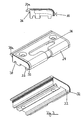
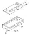
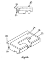
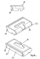
- Fig.1 an embodiment of the locking part 10 is shown, which consists of a box-shaped body 22, the upwardly facing opening is covered by the plate 24.
- This plate 24 has at least one recess 26, which receives a locking element 28 of a door or window 30 in use.
- Fig.1 an existing plastic edge 20a is shown, which overlaps in the use state for this locking part 10 facing end portion of the weatherboard 12.
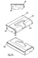
- the Fig.2 shows essentially the embodiment according to Fig.1
- the plate 24 is made of a hard material core, such as metal or glass fiber reinforced plastic, and is coated with a plastic.
- the in use state from above to be seen end edges of the locking part 10 are provided with a sealing device 32 which seals the transition to a locking bar 44, which will be described later.
- FIG. 3 is in addition to the embodiment of Fig.2 also shown a sealing star 36, which rests in use on the weatherboard 12. This increases the seal between weatherboard 12 and locking part 10th
- FIGS. 1 to 3 has a rounded in use state to the door side facing area
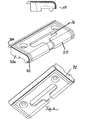
- Figure 4 an embodiment shown in which the box-shaped body 22 also indicates a wall in the door region and therefore also supports the plate 24 there.
- FIG. 5 shows the embodiment according to Figure 4 only with a sealing star 36 already described above.
- sealing devices 32a are still provided on the end faces, which can be used instead of the sealing strip 32 already described above or in addition thereto.
- Figure 6 is a combination of the embodiments according to the 2 to 5 shown.
- the linear sealing device 32 is also added.
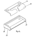
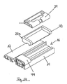
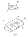
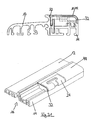
- the Figure 7 shows a locking member 10, wherein the box-shaped body 22 is formed substantially as a plate portion and the plate 24 engages the body 22 in such a bridge-shaped that seen in the longitudinal direction, the two ends of the locking member 10 are not covered by the plate 24.
- this embodiment also has two recesses 26 for receiving a locking element 28, which are formed opposite one another, starting from the free ends of the plate 24 to the center of the plate 24.
- FIG 8 two views of a threshold 16 are shown, with weather leg 12, hollow section 14, the locking part 10 according to Fig.1 and a subsequent locking bar 44th
- FIG 9 shows in a similar way as the Figure 8 the embodiment of the locking bar 44 according to Figure 4 in the installed state as part of the threshold 16.
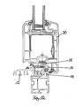
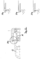
- the Figure 10 is a cross-sectional view of the threshold 16 in the mounted state with a closed door or on a closed window 30. It is clear to see how the locking element 28 engages in the there unspecified recess 26.
- the Figure 11 shows two ways to attach the locking part 10 and the locking bar 44, once with a pin not specified, which engages in an upwardly open cavity of the hollow section 14.
- the other possibility consists of a locking clip 46, which engages latching in the above-described hollow profile.
- the locking parts 10 can also be connected in other ways with the threshold elements.
- the locking part 10 can also be clamped or screwed into the rebate space 18.
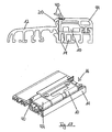
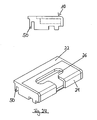
- Figure 12 is clearly shown that in the use state to the hollow profile 14 facing side of the box-shaped body 22 extending in the longitudinal direction venting channels 38 are formed.
- Figure 12 shows the embodiment according to Fig.1 in which the sealing edge 20a is not yet formed.
- the box-shaped body 22 provided with the plate 24 is open at the end sides in the longitudinal direction.
- the abovementioned arrangement is received in a pocket 42 made of soft plastic.
- this bag 42 may also consist of a hard plastic, in which case, however, the end faces are provided with corresponding sealing devices.
- the Figure 16 shows an embodiment according to Fig.2 similar embodiment.
- an additional sealing element 40 is provided above the edge 20a.
- the sealing element 40 is formed in the form of a half shell and extends in the longitudinal direction over the entire length of the locking part 10.
- the locking bar 44 is also provided with a corresponding sealing element 40.
- the sealing element 40 of the locking bar 44 is received in an unspecified groove. This unspecified groove is used when loading the sealing element 40, a portion of the material there so that, for example, a greater resistance is not exercised on a wheelchair.
- sealing elements 40 are in the Figure 18 shown.
- this is a brush or a tube.
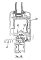
- the cross-sectional view according to Figure 19 shows the embodiment according to Figure 17 when completely installed with closed door or window 30th
- the upwardly-facing surface of the locking part 10 in use may at least partially be inclined in the direction of the edge 20a. This slope helps drain rainwater or condensation.
- the appropriately trained locking bar 44 is in fig.20 shown.
- the Figure 22 represents different cross-sectional views substantially the locking bar 44, the different shapes of the water-breaking edge 20a but also for the locking bar 44 are provided.
- the three enlargements of the area of the water-breaking edge 20a once show a sharp bevel, on the other hand a wedge-shaped groove and, for the third, a tooth shape in the form of a cross section.
- FIGS. 23 to 31 describe in essence embodiments of locking members 10, partially in connection with Arretianssologicaln 44, all of which have the above-mentioned section 20 which can be brought to rest on the end of the weatherboard 12. In this case, only the lengths of the sections 20 are partially different, which, for example, from a comparison of Figures 23 and 25 is recognizable.
- the embodiment corresponds to Fig. 23 essentially that of the Fig.1 , the embodiment according to Figure 24 essentially that of the Figure 4 , the embodiment according to Figure 25 essentially that of the Figure 13 , the embodiment according to Figure 26 essentially according to the locking part Figure 15 and the same applies to the embodiment according to Fig.27 ,
- the Figure 28 shows four views of a further embodiment, although also the web 50 and the section 20 in a somewhat extended manner, but has a completely different shaped body 20 at least on the bottom.
- the downwards in use state and connectable to the hollow section 14 underside is significantly enhanced compared to the other embodiments. This is intended to be able to use this locking part 10 for higher thresholds 16.
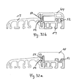
- FIGS. 32a and 32b are shown with respect to the previously described latching web 50 / locking groove 54 compounds.
- a detent groove 54 is used both for the latching web 50 of the closing part 10 and for the locking web 50 of the locking bar 44, which is formed between the weatherboard 12 and the hollow section 14 of corresponding walls.
- both locking devices 52 which are each arranged in the vicinity of the door stop side of the threshold 16, different shapes.
- these locking devices 52 can also take all the forms already described both for the closing part 10 and for the locking bar 44.
- a locking bar 44 Another innovation in this case is illustrated by a locking bar 44.
- This further innovation of course also applies to closing parts 10.
- the illustrated locking bar 44 has in the state of use to the door facing end of the weatherboard 12 a transversely of weatherboard 12 and the hollow part 14 pioneering projection 44a.
- This of course also applies to a non-illustrated closing part 10.
- the projection 44a then forms a Mosanschlagswand when doors are used whose distance from the ground is greater than the threshold arrangements already described.
- the body 22 in such a way that it can also serve for accommodating commercially available plates 24. Further, although not shown, it is possible to fasten, screw, clasp or glue the plate 24 to the box-shaped body.
- a threshold 16 should have a maximum height of 20 mm according to DIN 18025 "Barrier-free apartments". So that this height is not exceeded with the sealing element 40, this is folded away when driving over, for example, with a wheelchair or pressed. This is already above with reference to Figure 18 been mentioned.
- the sealing element 40 of the locking strip 44 can, as in Figure 17 to see, to the sealing element 40 of the locking part 10 projecting on the sides and slightly offset from the position of the sealing element 40 of the locking bar 44.
- both sealing element 40 can overlap in the installed state.
- a very good seal is achieved, which according to the current state of the art has always proved to be very problematic in conventional systems.
Landscapes
- Engineering & Computer Science (AREA)
- Civil Engineering (AREA)
- Structural Engineering (AREA)
- Specific Sealing Or Ventilating Devices For Doors And Windows (AREA)
- Wing Frames And Configurations (AREA)
Applications Claiming Priority (2)
| Application Number | Priority Date | Filing Date | Title |
|---|---|---|---|
| DE202006018782 | 2006-12-11 | ||
| DE202007002319U DE202007002319U1 (de) | 2007-02-13 | 2007-02-13 | Schließteil |
Publications (2)
| Publication Number | Publication Date |
|---|---|
| EP1932996A2 true EP1932996A2 (fr) | 2008-06-18 |
| EP1932996A3 EP1932996A3 (fr) | 2011-01-19 |
Family
ID=39046757
Family Applications (1)
| Application Number | Title | Priority Date | Filing Date |
|---|---|---|---|
| EP07023790A Withdrawn EP1932996A3 (fr) | 2006-12-11 | 2007-12-07 | Elément de fermeture |
Country Status (1)
| Country | Link |
|---|---|
| EP (1) | EP1932996A3 (fr) |
Cited By (1)
| Publication number | Priority date | Publication date | Assignee | Title |
|---|---|---|---|---|
| US20240254826A1 (en) * | 2023-01-27 | 2024-08-01 | Andersen Corporation | Multi-piece sill assembly for fenestrations |
Family Cites Families (3)
| Publication number | Priority date | Publication date | Assignee | Title |
|---|---|---|---|---|
| DE20204563U1 (de) * | 2002-03-21 | 2002-06-27 | Schüring GmbH & Co. Fenster-Technologie KG, 53842 Troisdorf | Thermisch isolierte Türschwelle |
| CA2501317A1 (fr) * | 2002-10-01 | 2004-04-15 | Premdor International Inc. | Ensemble rail reglable pour ensemble seuil de porte exterieur et elements associes |
| DE202005020240U1 (de) * | 2005-07-25 | 2006-12-07 | Frey, Inge | Bodenschwelle |
-
2007
- 2007-12-07 EP EP07023790A patent/EP1932996A3/fr not_active Withdrawn
Cited By (1)
| Publication number | Priority date | Publication date | Assignee | Title |
|---|---|---|---|---|
| US20240254826A1 (en) * | 2023-01-27 | 2024-08-01 | Andersen Corporation | Multi-piece sill assembly for fenestrations |
Also Published As
| Publication number | Publication date |
|---|---|
| EP1932996A3 (fr) | 2011-01-19 |
Similar Documents
| Publication | Publication Date | Title |
|---|---|---|
| EP3862525B1 (fr) | Seuil zéro pour les ascenseurs et les portes coulissantes | |
| EP1932997A2 (fr) | Fermeture supérieure d'un système de fermeture de seuil et seuil | |
| EP3043017B2 (fr) | Systeme de drainage pour des elements de porte et de fenetre | |
| CH676376A5 (en) | Strip-type door-leaf seal | |
| EP3112577B1 (fr) | Joint abaissable | |
| DE4338181C1 (de) | Kunststoff-Hohlprofil | |
| DE202007002319U1 (de) | Schließteil | |
| EP1459651A2 (fr) | Paroi superieure d'un tiroir compose de plusieurs elements individuels | |
| EP0306028B1 (fr) | Vantail de portail ou vantail de porte composé d'un ou de plusieurs parties et muni d'une serrure à barre | |
| EP1932996A2 (fr) | Elément de fermeture | |
| DE202004000817U1 (de) | Rahmenkörper aus einem hohlen, stranggepreßten Kunststoffprofil für Fenster und Türen | |
| DE9404779U1 (de) | Fenster- oder Türrahmen, insbesondere für darüber liegenden Rolladenkasteneinbau | |
| EP1262625A2 (fr) | Profilé de protection contre la pluie avec séparation thermique ou seuil | |
| EP1118744A2 (fr) | Joint d'étanchéité pour fenêtres, portes ou similaires | |
| CH672000A5 (fr) | ||
| DE19943195A1 (de) | Fenster, Tür o. dgl. sowie Rahmenprofil hierfür | |
| DE20306960U1 (de) | Beschlageinheit für Fenster oder Türen | |
| EP2362047B1 (fr) | Porte à levage coulissante ou fenêtre à levage coulissant | |
| EP4060157B1 (fr) | Portail pourvu de portillon | |
| EP4534793B1 (fr) | Ensemble porte ou fenêtre | |
| DE102007007659A1 (de) | Oberer Abschluss einer Schwelle, Abschluss-System sowie Schwelle | |
| DE202018104841U1 (de) | Verschlusselement zum Verschließen einer Öffnung | |
| DE3924054C2 (de) | Fensterrahmen, insbesondere aus Kunststoff und insbesondere für Kellerfenster | |
| DE60000324T2 (de) | Beschlagelement bzw. Schliessblech oder anderes in einer einklemmenden "u" oder "t" formigen Nut zu befestigen | |
| EP2072744A2 (fr) | Profilés dormants pour une porte coulissante relevable |
Legal Events
| Date | Code | Title | Description |
|---|---|---|---|
| PUAI | Public reference made under article 153(3) epc to a published international application that has entered the european phase |
Free format text: ORIGINAL CODE: 0009012 |
|
| AK | Designated contracting states |
Kind code of ref document: A2 Designated state(s): AT BE BG CH CY CZ DE DK EE ES FI FR GB GR HU IE IS IT LI LT LU LV MC MT NL PL PT RO SE SI SK TR |
|
| AX | Request for extension of the european patent |
Extension state: AL BA HR MK RS |
|
| PUAL | Search report despatched |
Free format text: ORIGINAL CODE: 0009013 |
|
| AK | Designated contracting states |
Kind code of ref document: A3 Designated state(s): AT BE BG CH CY CZ DE DK EE ES FI FR GB GR HU IE IS IT LI LT LU LV MC MT NL PL PT RO SE SI SK TR |
|
| AX | Request for extension of the european patent |
Extension state: AL BA HR MK RS |
|
| RAP1 | Party data changed (applicant data changed or rights of an application transferred) |
Owner name: ROTO GLUSKE-BKV GMBH |
|
| AKX | Designation fees paid |
Designated state(s): AT BE BG CH CY CZ DE DK EE ES FI FR GB GR HU IE IS IT LI LT LU LV MC MT NL PL PT RO SE SI SK TR |
|
| STAA | Information on the status of an ep patent application or granted ep patent |
Free format text: STATUS: THE APPLICATION IS DEEMED TO BE WITHDRAWN |
|
| 18D | Application deemed to be withdrawn |
Effective date: 20110720 |