EP1933342A1 - Vorrichtung und Verfahren zur differentialen Erkennung - Google Patents
Vorrichtung und Verfahren zur differentialen Erkennung Download PDFInfo
- Publication number
- EP1933342A1 EP1933342A1 EP07354051A EP07354051A EP1933342A1 EP 1933342 A1 EP1933342 A1 EP 1933342A1 EP 07354051 A EP07354051 A EP 07354051A EP 07354051 A EP07354051 A EP 07354051A EP 1933342 A1 EP1933342 A1 EP 1933342A1
- Authority
- EP
- European Patent Office
- Prior art keywords
- ribbon
- end portion
- torus
- detection
- core
- Prior art date
- Legal status (The legal status is an assumption and is not a legal conclusion. Google has not performed a legal analysis and makes no representation as to the accuracy of the status listed.)
- Granted
Links
Images

Classifications
-
- H—ELECTRICITY
- H01—ELECTRIC ELEMENTS
- H01F—MAGNETS; INDUCTANCES; TRANSFORMERS; SELECTION OF MATERIALS FOR THEIR MAGNETIC PROPERTIES
- H01F38/00—Adaptations of transformers or inductances for specific applications or functions
- H01F38/20—Instruments transformers
- H01F38/22—Instruments transformers for single phase AC
- H01F38/28—Current transformers
- H01F38/30—Constructions
-
- H—ELECTRICITY
- H01—ELECTRIC ELEMENTS
- H01F—MAGNETS; INDUCTANCES; TRANSFORMERS; SELECTION OF MATERIALS FOR THEIR MAGNETIC PROPERTIES
- H01F27/00—Details of transformers or inductances, in general
- H01F27/24—Magnetic cores
- H01F27/25—Magnetic cores made from strips or ribbons
-
- H—ELECTRICITY
- H01—ELECTRIC ELEMENTS
- H01H—ELECTRIC SWITCHES; RELAYS; SELECTORS; EMERGENCY PROTECTIVE DEVICES
- H01H83/00—Protective switches, e.g. circuit-breaking switches, or protective relays operated by abnormal electrical conditions otherwise than solely by excess current
- H01H83/14—Protective switches, e.g. circuit-breaking switches, or protective relays operated by abnormal electrical conditions otherwise than solely by excess current operated by imbalance of two or more currents or voltages, e.g. for differential protection
- H01H83/144—Protective switches, e.g. circuit-breaking switches, or protective relays operated by abnormal electrical conditions otherwise than solely by excess current operated by imbalance of two or more currents or voltages, e.g. for differential protection with differential transformer
-
- H—ELECTRICITY
- H01—ELECTRIC ELEMENTS
- H01F—MAGNETS; INDUCTANCES; TRANSFORMERS; SELECTION OF MATERIALS FOR THEIR MAGNETIC PROPERTIES
- H01F27/00—Details of transformers or inductances, in general
- H01F27/34—Special means for preventing or reducing unwanted electric or magnetic effects, e.g. no-load losses, reactive currents, harmonics, oscillations, leakage fields
-
- H—ELECTRICITY
- H01—ELECTRIC ELEMENTS
- H01H—ELECTRIC SWITCHES; RELAYS; SELECTORS; EMERGENCY PROTECTIVE DEVICES
- H01H83/00—Protective switches, e.g. circuit-breaking switches, or protective relays operated by abnormal electrical conditions otherwise than solely by excess current
- H01H83/14—Protective switches, e.g. circuit-breaking switches, or protective relays operated by abnormal electrical conditions otherwise than solely by excess current operated by imbalance of two or more currents or voltages, e.g. for differential protection
- H01H83/144—Protective switches, e.g. circuit-breaking switches, or protective relays operated by abnormal electrical conditions otherwise than solely by excess current operated by imbalance of two or more currents or voltages, e.g. for differential protection with differential transformer
- H01H2083/146—Provisions for avoiding disadvantages of having asymetrical primaries, e.g. induction of a magnetic field even by zero difference current
Definitions
- the invention relates to the differential interruption of electrical equipment, and in particular the reliability of the high-current trip.
- the invention relates to a toroid used for the detection of differential currents and the optimization of its geometry to reduce parasitic secondary signal generation.
- the invention also relates to a differential detection device and immune protection against inadvertent tripping.
- the vector sum of the departure and return currents should be zero; however, malfunctions may occur, such as a ground fault, and a residual differential current between the line conductors remains.
- the electrical line to be verified is surrounded by a magnetic permeability ring greater than that of the air which concentrates the eventual residual magnetic field.
- a so-called secondary winding around the ring will then be the source of a voltage proportional to the magnetic field in the ring, the signal of which makes it possible to determine the differential primary intensity in the conductors of the line.
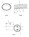
- the detection rings are thus in the form of cores 2, illustrated in Figures 1A and 1B formed of a ribbon 4 of high magnetic permeability material wound on itself.
- the ribbon 4 is of substantially constant section; its length allows the formation of a number of turns, or layers, 6 i depending on the desired capabilities of the ring, between one end 8 of the ribbon becoming an inner end of the core 2, and the other.
- the torus 2 is provided with a secondary winding 10, the turns of which, in a variable number, extend in the frame shown in FIG. figure 1C 360 °.
- the torus 2 is positioned around the line to be checked which, in the illustrated case, consists of two copper bars 12; it is understood that this example is illustrative and that the two bars 12 can in particular be replaced by the primary winding of four son of a three-phase supply with neutral as described in FR 2,749,987 , or any other embodiment.
- a secondary signal is detected in the winding 10 by the processing means 14 which can give an estimate of the secondary signal or the corresponding differential primary current. If a threshold is reached, in particular 30 mA for the primary differential current, a trip relay 16 sends a signal to cut-off systems associated with the primary conductors 12, in order to disconnect the installation concerned.
- the invention aims to overcome the drawbacks of existing systems and in particular to avoid erroneous detection of differential currents that may cause inadvertent tripping of a switchgear.
- the geometry of the detection core is optimized so that the magnetic flux passing through the core is homogenized, and does not generate parasitic secondary signals.
- the invention relates to a torus that can be used for the differential detection in which one of the end portions of the ribbon forming the core is provided with means allowing the magnetic flux to flow more homogeneously, being distributed over an upper length of turn.
- the torus according to the invention comprises a ribbon of magnetic material of substantially constant section and wound, advantageously circularly, to form a succession of turns, which are contiguous to each other by opposite sides of the ribbon.
- the ribbon comprises two ends with associated end portions of predetermined length, advantageously corresponding to a torus turn. At least one of the end portions, corresponding to and extending the inner end of the ribbon in the torus, is provided with means for homogenizing the magnetic flux.
- the homogenization of the magnetic flux is obtained by a modification, and in particular a gradual decrease, preferably a continuous decay, of the apparent density of magnetic material in the volume defined by the ribbon at the end portion and the turn which is adjacent to it in the presence of the homogenization means, with respect to the same value without said homogenization means.
- the homogenization means modify the magnetic coupling between the end portion and the turn adjacent thereto, so that this coupling is increasing from the end.
- the decrease of the relative density can be obtained by "lightening" of the end portion, by removal or reduction in material of the section and / or the surface of the ribbon, that is to say more generally a lightening element.
- the flow homogenization means may for example consist of a recess within the ribbon on the end portion, such as a hole, which may in particular be triangular, so that the end portion contains a decreasing amount of magnetic material. towards the end.
- the recess may be formed of a plurality of orifices, preferably transverse to the ribbon, and of increasing length towards the end of the ribbon.
- the lightening member may be made by cutting the ribbon at an edge of the end portion, or its edges, thereby forming a tip toward the end concerned. A decrease in thickness would also be possible.
- the homogenization means can in particular take the form of a wedge inserted between the end of the ribbon and the adjacent turn.
- the shim is inserted a distance corresponding to the end portion and its profile is adapted for a steady progression in the spacing between the turns. It is also possible to position several spacers of different heights at different levels between the inner turn and the adjacent turn.
- the invention furthermore relates to a device for detecting differential currents comprising a toroid as defined above, surrounded, preferably over its entire circumference, by a secondary winding, and associated with means for processing the secondary signal supplied by said winding. , signal representative of a differential primary current inside the toroid.
- the invention in another aspect, relates to a device for differential breaking of a primary conductor line, preferably integrated.
- the apparatus comprises a device for detecting differential currents as defined above, the primary conductors associated with a cutoff system traversing the torus of the detection device, and a tripping relay controlling the cutoff system according to the data from the processing means of the detection device.
- FIGS. 1A, 1B and 1C already described, show a differential detection torus according to the state of the art and a switchgear.
- the figure 2 illustrates a first embodiment of the invention.
- FIGS. 4A and 4B represent an alternative embodiment of the figure 3 .
- the inventors have found that one of the causes of inadvertent generation of secondary signals relates to the shape of the torus 2 of detection.
- the magnetic flux B from the primary circuit 12 passes through the torus 2 following the layers 6 i of magnetic tape; the very thin air gaps existing between each turn 6 i slow the passage of the flow B from one layer of material to another.
- the flow B flowing in the first layer 6 1 must pass into the second 6 2 , creating a local increase in flux that can not always be absorbed by the following layers 6 i and causes saturation fast of the adjacent layer 6 2 .
- This saturation not symmetrical with respect to the conductors 12, unbalances the magnetic field B of the core 2, causing the appearance of a secondary signal in the winding 10.
- the detection means 14 can deduce, for a primary current of the order of 400 A single phase in the conductors 12, a primary differential current of the order of 12-15 mA, c ' that is, 50% of the conventional trigger.
- the invention proposes to locally reduce the flow irregularity caused by the end of the ribbon 8 by the presence of homogenization means at the corresponding end portion 18 of the ribbon 4.
- the homogenizing means are such that the density of magnetic material (component ribbon 4) present in the volume delimited by the end portion 18 provided with said homogenizing means and the adjacent turn 6 2 (considering for each non-contiguous faces of the ribbon 4) relative to the same volume without the homogenization means decreases gradually towards the end 8. In this way, the magnetic coupling between the end portion 18 and the turn 6 2 increases gradually from the end 8, and its distribution is more homogeneous.
- the homogenization means can take different forms, which can be combined within the same torus 2 and / or accumulated on the same end portion 18; although the various embodiments are presented in relation to the inner end 8 of the torus 2 where the majority of the magnetic flux is concentrated, the homogenization means may concern both ends of the ribbon.
- the preferred embodiments relate to the distribution of the passage of the magnetic flux from the first to the second turn over the entire inner circumference of the core 2; it would however also be possible, in particular according to the length of the secondary winding 10, to arrange the homogenization means on only a part of the circumference of the core 2, for example over at least 45 ° or 90 ° of arc, or even on a turn, or, in some cases, to develop the homogenization means on more than one turn, for example two turns 6 1 , 6 2 of ribbon 4. It should also be understood that, although represented circular, the The winding of the ribbon 4 forming the core 2 is not limited to this geometrical shape and the known alternatives, such as an oblong or rectangular shape, for the differential detection cores are included in this term.
- the homogenization means increase the volume between the end portion 18 and the ribbon 4 of the adjacent turn 6 2 by the spacing of the end portion 18: see figure 2 .
- the volume delimited by the ribbon 4 of the two adjacent turns 6 1 , 6 2 at the end portion 18 is then greater than the corresponding volume without separation due to the homogenizing means, for the same quantity of magnetic material, and the relative density of magnetic material decreases.
- the first turn 6 1 is separated from the adjacent turn 2 , and this over a length of end portion 18, preferably equal to one turn; as the reluctance between the first layer 6 1 and the second 6 2 depends on their spacing (and therefore increases), the flow B transiting from the first turn 6 1 to the second 6 2 is gradually limited.
- the nonmagnetic wedge 20 is made of plastic, of a height of the order of the thickness of the ribbon 4, or half; in particular, the shim 20 has a height of the order of 0.1 mm at the end 8 of a ribbon 4 with a thickness of 100 to 200 ⁇ m for a torus diameter 2 of the order of 4 cm, for example for a torus 2 as previously presented.
- the joining between turns 6 i of the core 2 is retained, and the decrease in inhomogeneities of flux is achieved by a local modification of the shape of the ribbon 4, thanks to the presence of a element of lightening.
- This embodiment is advantageous because it can be implemented upstream: preferably, the actions on the end portion 18 of the ribbon 4 are performed before shaping the core 2, the ribbon 4 being flat, and before the possible annealing phases in a magnetic field that provide the magnetic materials their properties.
- the tape 4 once altered is meanwhile wound in the usual way in the form of torus 2.
- the homogenization means are made by a gradient of the thickness of the ribbon 4 towards the end 8: the usually uniform section of the ribbon 4 is modified on the part of end 18 by cutting or mechanical stress. This results in a decrease in thickness which allows a reduction of field dissymmetries by its distribution throughout the end portion 18.
- the amount of material present is less for the same surface of the ribbon and the density of the material in the space delimited by two thicknesses of ribbon 4 decreases relatively.
- this variant can be difficult to achieve, and a second variant, possibly in combination with the first, recommends performing the lightening material of the end portion 18 in the direction of the width of the ribbon 4 rather than its thickness, gradually reducing its useful width.
- the ribbon 4 is bevelled towards the end 8 to form a substantially triangular tip 28: the homogenizing means 30 are then identified by the "empty" portion complementary to the tip 28.
- the width of the ribbon in the end portion 18 thus gradually decreases, which allows a gradual transfer of magnetic flux B from the first turn 6 1 to the second 6 2 ; the local saturation of the second layer 6 2 is avoided, considerably limiting the parasitic secondary signals and therefore the false differential primary currents.
- the defect in the distribution of the magnetic field B due to the passage of a turn 6 1 to the other 6 2 is actually averaged over the torus 2, and no longer concentrated in a single point 8.
- the lightening element concerns only one side of the ribbon, as illustrated: for a narrow ribbon 4 and a torus 2 of a consequent diameter in which it is desired to form an end portion 18 of length corresponding to the first turn 6 1 , the beveling of a only side of the ribbon 4 increases the cutting angle for more accuracy and ease.
- the available sampling means and the size of the ribbon 4 it is possible to cut the end portion on its two edges, for example by positioning the end 8 at the center of the ribbon 4; this embodiment may also be preferred in the case of a direct manufacture of the ribbon 4 with a profiled end 18.
- the profiled end 28 of the ribbon 4 can twist at the cut.
- the twisted part can be cut or glued to the second layer 6 2 .
- a recess 40 for example of triangular shape, can be created in the end portion 18: the strip of material 42 remaining at the end of the recess 40 at the end 8 can be used to maintain the first turn 6 1 during shaping torus 2, for example by hanging on an axis to wind the ribbon 4.
- the recess 40 is formed by a plurality of orifices 44 i , for example crosswise in the width, which are inscribed therein: see Figure 4B .
- the decrease in relative density is here less regular than in the other embodiments, this option can be particularly advantageous in terms of manufacturing, by "punching" for example the ribbon 4 on the end portion 18.
- the torus 2 according to the invention may be used in any detection system differential 2, 10, 14, in particular for an interruption device as illustrated in FIG. figure 1C .
- the shape and the homogenization length of the stream can be optimized depending on the magnetic material chosen, the expected nominal current, the shape of the torus considered, etc.
Landscapes
- Engineering & Computer Science (AREA)
- Power Engineering (AREA)
- Transformers For Measuring Instruments (AREA)
- Measuring Instrument Details And Bridges, And Automatic Balancing Devices (AREA)
- Measuring Magnetic Variables (AREA)
- Retarders (AREA)
- Analysing Materials By The Use Of Radiation (AREA)
- Investigating Or Analyzing Materials By The Use Of Magnetic Means (AREA)
Applications Claiming Priority (1)
| Application Number | Priority Date | Filing Date | Title |
|---|---|---|---|
| FR0610827A FR2909800B1 (fr) | 2006-12-12 | 2006-12-12 | Tore et dispositif de detection differentielle. |
Publications (2)
| Publication Number | Publication Date |
|---|---|
| EP1933342A1 true EP1933342A1 (de) | 2008-06-18 |
| EP1933342B1 EP1933342B1 (de) | 2009-07-29 |
Family
ID=38325440
Family Applications (1)
| Application Number | Title | Priority Date | Filing Date |
|---|---|---|---|
| EP07354051A Not-in-force EP1933342B1 (de) | 2006-12-12 | 2007-10-03 | Vorrichtung und Verfahren zur differentialen Erkennung |
Country Status (6)
| Country | Link |
|---|---|
| EP (1) | EP1933342B1 (de) |
| CN (1) | CN101226822B (de) |
| AT (1) | ATE438190T1 (de) |
| DE (1) | DE602007001769D1 (de) |
| ES (1) | ES2328415T3 (de) |
| FR (1) | FR2909800B1 (de) |
Citations (8)
| Publication number | Priority date | Publication date | Assignee | Title |
|---|---|---|---|---|
| US2759128A (en) * | 1952-07-31 | 1956-08-14 | I T E Circnit Breaker Company | Reactors |
| FR2502834A1 (fr) * | 1981-03-25 | 1982-10-01 | Magnetic Metals Gmbh | Noyau de transformateur differentiel pour courants pulsatoires et interrupteur de protection contre des courants de fuite utilisant un tel noyau |
| EP0076999A2 (de) * | 1981-10-14 | 1983-04-20 | Siemens Aktiengesellschaft | Anordnung zur Vermeidung von Fehlimpulsen eines Summenstromwandlers |
| EP0813283A1 (de) * | 1996-06-14 | 1997-12-17 | Schneider Electric Sa | Gegen unbeabsichtigtes Auslösen immunisiertes Differentialschutz |
| DE19710742A1 (de) * | 1997-03-14 | 1998-09-24 | Siemens Ag | Summenstrom-Wandleranordnung |
| US6023216A (en) * | 1998-07-20 | 2000-02-08 | Ohio Transformer | Transformer coil and method |
| FR2799840A1 (fr) * | 1999-10-15 | 2001-04-20 | Rs Isolsec | Capteur de courant differentiel |
| EP1596205B1 (de) * | 2004-05-10 | 2007-02-28 | Areva T&D SA | Rogowski-Stromwandler mit zusammengesetzte Teilschaltungen zur Bildung einer Vollschaltung |
Family Cites Families (2)
| Publication number | Priority date | Publication date | Assignee | Title |
|---|---|---|---|---|
| DE10237255C5 (de) * | 2002-08-14 | 2009-05-20 | Deutsch-Französisches Forschungsinstitut Saint-Louis, Saint-Louis | Transformatorspule |
| CN100576376C (zh) * | 2004-03-29 | 2009-12-30 | 达特默斯大学托管会 | 有隙铁芯上的磁性线圈的低交流电阻箔式绕组 |
-
2006
- 2006-12-12 FR FR0610827A patent/FR2909800B1/fr not_active Expired - Fee Related
-
2007
- 2007-10-03 ES ES07354051T patent/ES2328415T3/es active Active
- 2007-10-03 DE DE602007001769T patent/DE602007001769D1/de active Active
- 2007-10-03 EP EP07354051A patent/EP1933342B1/de not_active Not-in-force
- 2007-10-03 AT AT07354051T patent/ATE438190T1/de not_active IP Right Cessation
- 2007-12-12 CN CN2007101997366A patent/CN101226822B/zh not_active Expired - Fee Related
Patent Citations (8)
| Publication number | Priority date | Publication date | Assignee | Title |
|---|---|---|---|---|
| US2759128A (en) * | 1952-07-31 | 1956-08-14 | I T E Circnit Breaker Company | Reactors |
| FR2502834A1 (fr) * | 1981-03-25 | 1982-10-01 | Magnetic Metals Gmbh | Noyau de transformateur differentiel pour courants pulsatoires et interrupteur de protection contre des courants de fuite utilisant un tel noyau |
| EP0076999A2 (de) * | 1981-10-14 | 1983-04-20 | Siemens Aktiengesellschaft | Anordnung zur Vermeidung von Fehlimpulsen eines Summenstromwandlers |
| EP0813283A1 (de) * | 1996-06-14 | 1997-12-17 | Schneider Electric Sa | Gegen unbeabsichtigtes Auslösen immunisiertes Differentialschutz |
| DE19710742A1 (de) * | 1997-03-14 | 1998-09-24 | Siemens Ag | Summenstrom-Wandleranordnung |
| US6023216A (en) * | 1998-07-20 | 2000-02-08 | Ohio Transformer | Transformer coil and method |
| FR2799840A1 (fr) * | 1999-10-15 | 2001-04-20 | Rs Isolsec | Capteur de courant differentiel |
| EP1596205B1 (de) * | 2004-05-10 | 2007-02-28 | Areva T&D SA | Rogowski-Stromwandler mit zusammengesetzte Teilschaltungen zur Bildung einer Vollschaltung |
Non-Patent Citations (1)
| Title |
|---|
| COLIN ET AL: "Effects of magnetic core geometry on false detection in residual current sensor", JOURNAL OF MAGNETISM AND MAGNETIC MATERIALS, ELSEVIER SCIENCE PUBLISHERS, AMSTERDAM, NL, vol. 304, no. 2, September 2006 (2006-09-01), pages e804 - e806, XP005479260, ISSN: 0304-8853 * |
Also Published As
| Publication number | Publication date |
|---|---|
| ATE438190T1 (de) | 2009-08-15 |
| EP1933342B1 (de) | 2009-07-29 |
| DE602007001769D1 (de) | 2009-09-10 |
| ES2328415T3 (es) | 2009-11-12 |
| CN101226822B (zh) | 2011-09-28 |
| CN101226822A (zh) | 2008-07-23 |
| FR2909800A1 (fr) | 2008-06-13 |
| FR2909800B1 (fr) | 2009-01-09 |
Similar Documents
| Publication | Publication Date | Title |
|---|---|---|
| EP1596206B1 (de) | Elektrische Strommessanordnung, Stromsensor, elektrischer Auslöser und Trennschalter mit einer derartigen Strommessanordnung | |
| EP2568301B1 (de) | Stromsensor und Leiterplatte für einen solchen Sensor | |
| EP1596205B1 (de) | Rogowski-Stromwandler mit zusammengesetzte Teilschaltungen zur Bildung einer Vollschaltung | |
| EP2896114B1 (de) | Rotor einer elektrischen rotationsmaschine mit einem läuferkörper mit aussparungen | |
| EP0853766A1 (de) | Magnetfeldsensor mit einer magnetowiderstandsbrücke | |
| EP1971841A2 (de) | Magnetischer kurzhubpositionssensor, im besonderen zur messung von lenksäulendrehungen | |
| FR3044096A1 (fr) | Capteur de courant et dispositif pour la mesure d'un courant electrique | |
| EP2288925A1 (de) | Sensor für permante oder variable magnetfeldzirkulation und stromsensor mit derartigem sensor | |
| EP2887076B1 (de) | Stromsensor mit Rogowskispule, und Herstellungsverfahren eines solchen Stromsensors | |
| EP1852707B1 (de) | Fluxgate-Mikromagnetometer mit verbesserter Anregungswicklung | |
| EP3635753B1 (de) | Vorrichtung zur erkennung eines kurzschlusses, schutzvorrichtung und zugehöriges verfahren für ein hochspannungsgleichstromnetz | |
| EP3290930A1 (de) | Strommesssensor vom typ rogowski-spule, messvorrichtung und elektrischer trennschalter, der einen solchen sensor umfasst, und spulenwicklungsverfahren eines solchen sensors | |
| EP1646126A1 (de) | Rotor für eine elektrische Maschine und diesen enthaltende elektrische Maschine | |
| EP4073916A1 (de) | Supraleitendes pellet, das einen hohlraum umfasst, und zugehörige elektrische maschine | |
| EP1933342B1 (de) | Vorrichtung und Verfahren zur differentialen Erkennung | |
| FR3013500A1 (fr) | Bobine de rogowski et procede de fabrication associe | |
| WO2021099724A1 (fr) | Dispositif d'induction electromagnetique | |
| FR2981761A1 (fr) | Element magneto-plasmonique a non-reciprocite modifiee, exaltee ou inversee, composant integrant de tels elements, et procede de fabrication. | |
| FR2521377A1 (fr) | Appareil d'enregistrement et de lecture optique | |
| FR3068464A1 (fr) | Capteur de position inductif avec spires secondaires traversant une carte de circuit imprime | |
| EP3443365B1 (de) | Vorrichtung zur messung von elektrischen strömen | |
| EP2880453B1 (de) | Gerät zur messung eines in einem leiter fliessenden stroms | |
| EP3977148B1 (de) | Magnetfeldsensor | |
| FR2799840A1 (fr) | Capteur de courant differentiel | |
| EP3899434B1 (de) | Rotor für induktiven winkelbewegungssensor |
Legal Events
| Date | Code | Title | Description |
|---|---|---|---|
| PUAI | Public reference made under article 153(3) epc to a published international application that has entered the european phase |
Free format text: ORIGINAL CODE: 0009012 |
|
| AK | Designated contracting states |
Kind code of ref document: A1 Designated state(s): AT BE BG CH CY CZ DE DK EE ES FI FR GB GR HU IE IS IT LI LT LU LV MC MT NL PL PT RO SE SI SK TR |
|
| AX | Request for extension of the european patent |
Extension state: AL BA HR MK RS |
|
| 17P | Request for examination filed |
Effective date: 20080707 |
|
| AKX | Designation fees paid |
Designated state(s): AT BE BG CH CY CZ DE DK EE ES FI FR GB GR HU IE IS IT LI LT LU LV MC MT NL PL PT RO SE SI SK TR |
|
| GRAP | Despatch of communication of intention to grant a patent |
Free format text: ORIGINAL CODE: EPIDOSNIGR1 |
|
| RAP1 | Party data changed (applicant data changed or rights of an application transferred) |
Owner name: SCHNEIDER ELECTRIC INDUSTRIES SAS |
|
| GRAS | Grant fee paid |
Free format text: ORIGINAL CODE: EPIDOSNIGR3 |
|
| GRAA | (expected) grant |
Free format text: ORIGINAL CODE: 0009210 |
|
| AK | Designated contracting states |
Kind code of ref document: B1 Designated state(s): AT BE BG CH CY CZ DE DK EE ES FI FR GB GR HU IE IS IT LI LT LU LV MC MT NL PL PT RO SE SI SK TR |
|
| REG | Reference to a national code |
Ref country code: GB Ref legal event code: FG4D Free format text: NOT ENGLISH |
|
| REG | Reference to a national code |
Ref country code: CH Ref legal event code: EP |
|
| REG | Reference to a national code |
Ref country code: IE Ref legal event code: FG4D |
|
| REF | Corresponds to: |
Ref document number: 602007001769 Country of ref document: DE Date of ref document: 20090910 Kind code of ref document: P |
|
| REG | Reference to a national code |
Ref country code: ES Ref legal event code: FG2A Ref document number: 2328415 Country of ref document: ES Kind code of ref document: T3 |
|
| NLV1 | Nl: lapsed or annulled due to failure to fulfill the requirements of art. 29p and 29m of the patents act | ||
| PG25 | Lapsed in a contracting state [announced via postgrant information from national office to epo] |
Ref country code: AT Free format text: LAPSE BECAUSE OF FAILURE TO SUBMIT A TRANSLATION OF THE DESCRIPTION OR TO PAY THE FEE WITHIN THE PRESCRIBED TIME-LIMIT Effective date: 20090729 Ref country code: LT Free format text: LAPSE BECAUSE OF FAILURE TO SUBMIT A TRANSLATION OF THE DESCRIPTION OR TO PAY THE FEE WITHIN THE PRESCRIBED TIME-LIMIT Effective date: 20090729 Ref country code: SE Free format text: LAPSE BECAUSE OF FAILURE TO SUBMIT A TRANSLATION OF THE DESCRIPTION OR TO PAY THE FEE WITHIN THE PRESCRIBED TIME-LIMIT Effective date: 20090729 Ref country code: IS Free format text: LAPSE BECAUSE OF FAILURE TO SUBMIT A TRANSLATION OF THE DESCRIPTION OR TO PAY THE FEE WITHIN THE PRESCRIBED TIME-LIMIT Effective date: 20091129 Ref country code: FI Free format text: LAPSE BECAUSE OF FAILURE TO SUBMIT A TRANSLATION OF THE DESCRIPTION OR TO PAY THE FEE WITHIN THE PRESCRIBED TIME-LIMIT Effective date: 20090729 |
|
| PG25 | Lapsed in a contracting state [announced via postgrant information from national office to epo] |
Ref country code: PL Free format text: LAPSE BECAUSE OF FAILURE TO SUBMIT A TRANSLATION OF THE DESCRIPTION OR TO PAY THE FEE WITHIN THE PRESCRIBED TIME-LIMIT Effective date: 20090729 Ref country code: SI Free format text: LAPSE BECAUSE OF FAILURE TO SUBMIT A TRANSLATION OF THE DESCRIPTION OR TO PAY THE FEE WITHIN THE PRESCRIBED TIME-LIMIT Effective date: 20090729 Ref country code: NL Free format text: LAPSE BECAUSE OF FAILURE TO SUBMIT A TRANSLATION OF THE DESCRIPTION OR TO PAY THE FEE WITHIN THE PRESCRIBED TIME-LIMIT Effective date: 20090729 Ref country code: LV Free format text: LAPSE BECAUSE OF FAILURE TO SUBMIT A TRANSLATION OF THE DESCRIPTION OR TO PAY THE FEE WITHIN THE PRESCRIBED TIME-LIMIT Effective date: 20090729 |
|
| REG | Reference to a national code |
Ref country code: IE Ref legal event code: FD4D |
|
| PG25 | Lapsed in a contracting state [announced via postgrant information from national office to epo] |
Ref country code: PT Free format text: LAPSE BECAUSE OF FAILURE TO SUBMIT A TRANSLATION OF THE DESCRIPTION OR TO PAY THE FEE WITHIN THE PRESCRIBED TIME-LIMIT Effective date: 20091129 Ref country code: BG Free format text: LAPSE BECAUSE OF FAILURE TO SUBMIT A TRANSLATION OF THE DESCRIPTION OR TO PAY THE FEE WITHIN THE PRESCRIBED TIME-LIMIT Effective date: 20091029 |
|
| BERE | Be: lapsed |
Owner name: SCHNEIDER ELECTRIC INDUSTRIES SAS Effective date: 20091031 |
|
| PG25 | Lapsed in a contracting state [announced via postgrant information from national office to epo] |
Ref country code: DK Free format text: LAPSE BECAUSE OF FAILURE TO SUBMIT A TRANSLATION OF THE DESCRIPTION OR TO PAY THE FEE WITHIN THE PRESCRIBED TIME-LIMIT Effective date: 20090729 Ref country code: IE Free format text: LAPSE BECAUSE OF FAILURE TO SUBMIT A TRANSLATION OF THE DESCRIPTION OR TO PAY THE FEE WITHIN THE PRESCRIBED TIME-LIMIT Effective date: 20090729 Ref country code: RO Free format text: LAPSE BECAUSE OF FAILURE TO SUBMIT A TRANSLATION OF THE DESCRIPTION OR TO PAY THE FEE WITHIN THE PRESCRIBED TIME-LIMIT Effective date: 20090729 Ref country code: EE Free format text: LAPSE BECAUSE OF FAILURE TO SUBMIT A TRANSLATION OF THE DESCRIPTION OR TO PAY THE FEE WITHIN THE PRESCRIBED TIME-LIMIT Effective date: 20090729 Ref country code: CZ Free format text: LAPSE BECAUSE OF FAILURE TO SUBMIT A TRANSLATION OF THE DESCRIPTION OR TO PAY THE FEE WITHIN THE PRESCRIBED TIME-LIMIT Effective date: 20090729 |
|
| PG25 | Lapsed in a contracting state [announced via postgrant information from national office to epo] |
Ref country code: MC Free format text: LAPSE BECAUSE OF NON-PAYMENT OF DUE FEES Effective date: 20091031 Ref country code: SK Free format text: LAPSE BECAUSE OF FAILURE TO SUBMIT A TRANSLATION OF THE DESCRIPTION OR TO PAY THE FEE WITHIN THE PRESCRIBED TIME-LIMIT Effective date: 20090729 |
|
| PLBE | No opposition filed within time limit |
Free format text: ORIGINAL CODE: 0009261 |
|
| STAA | Information on the status of an ep patent application or granted ep patent |
Free format text: STATUS: NO OPPOSITION FILED WITHIN TIME LIMIT |
|
| 26N | No opposition filed |
Effective date: 20100503 |
|
| PG25 | Lapsed in a contracting state [announced via postgrant information from national office to epo] |
Ref country code: GR Free format text: LAPSE BECAUSE OF FAILURE TO SUBMIT A TRANSLATION OF THE DESCRIPTION OR TO PAY THE FEE WITHIN THE PRESCRIBED TIME-LIMIT Effective date: 20091030 Ref country code: BE Free format text: LAPSE BECAUSE OF NON-PAYMENT OF DUE FEES Effective date: 20091031 |
|
| PG25 | Lapsed in a contracting state [announced via postgrant information from national office to epo] |
Ref country code: LU Free format text: LAPSE BECAUSE OF NON-PAYMENT OF DUE FEES Effective date: 20091003 Ref country code: MT Free format text: LAPSE BECAUSE OF FAILURE TO SUBMIT A TRANSLATION OF THE DESCRIPTION OR TO PAY THE FEE WITHIN THE PRESCRIBED TIME-LIMIT Effective date: 20090729 |
|
| PG25 | Lapsed in a contracting state [announced via postgrant information from national office to epo] |
Ref country code: HU Free format text: LAPSE BECAUSE OF FAILURE TO SUBMIT A TRANSLATION OF THE DESCRIPTION OR TO PAY THE FEE WITHIN THE PRESCRIBED TIME-LIMIT Effective date: 20100130 |
|
| PG25 | Lapsed in a contracting state [announced via postgrant information from national office to epo] |
Ref country code: TR Free format text: LAPSE BECAUSE OF FAILURE TO SUBMIT A TRANSLATION OF THE DESCRIPTION OR TO PAY THE FEE WITHIN THE PRESCRIBED TIME-LIMIT Effective date: 20090729 |
|
| PG25 | Lapsed in a contracting state [announced via postgrant information from national office to epo] |
Ref country code: CY Free format text: LAPSE BECAUSE OF FAILURE TO SUBMIT A TRANSLATION OF THE DESCRIPTION OR TO PAY THE FEE WITHIN THE PRESCRIBED TIME-LIMIT Effective date: 20090729 |
|
| PG25 | Lapsed in a contracting state [announced via postgrant information from national office to epo] |
Ref country code: IT Free format text: LAPSE BECAUSE OF NON-PAYMENT OF DUE FEES Effective date: 20101003 |
|
| REG | Reference to a national code |
Ref country code: CH Ref legal event code: PL |
|
| GBPC | Gb: european patent ceased through non-payment of renewal fee |
Effective date: 20111003 |
|
| PG25 | Lapsed in a contracting state [announced via postgrant information from national office to epo] |
Ref country code: LI Free format text: LAPSE BECAUSE OF NON-PAYMENT OF DUE FEES Effective date: 20111031 Ref country code: CH Free format text: LAPSE BECAUSE OF NON-PAYMENT OF DUE FEES Effective date: 20111031 |
|
| PG25 | Lapsed in a contracting state [announced via postgrant information from national office to epo] |
Ref country code: GB Free format text: LAPSE BECAUSE OF NON-PAYMENT OF DUE FEES Effective date: 20111003 |
|
| REG | Reference to a national code |
Ref country code: FR Ref legal event code: PLFP Year of fee payment: 10 |
|
| REG | Reference to a national code |
Ref country code: FR Ref legal event code: PLFP Year of fee payment: 11 |
|
| REG | Reference to a national code |
Ref country code: FR Ref legal event code: PLFP Year of fee payment: 12 |
|
| PGFP | Annual fee paid to national office [announced via postgrant information from national office to epo] |
Ref country code: FR Payment date: 20221024 Year of fee payment: 16 |
|
| PGFP | Annual fee paid to national office [announced via postgrant information from national office to epo] |
Ref country code: IT Payment date: 20221020 Year of fee payment: 16 Ref country code: ES Payment date: 20221117 Year of fee payment: 16 Ref country code: DE Payment date: 20221028 Year of fee payment: 16 |
|
| REG | Reference to a national code |
Ref country code: DE Ref legal event code: R119 Ref document number: 602007001769 Country of ref document: DE |
|
| PG25 | Lapsed in a contracting state [announced via postgrant information from national office to epo] |
Ref country code: FR Free format text: LAPSE BECAUSE OF NON-PAYMENT OF DUE FEES Effective date: 20231031 Ref country code: DE Free format text: LAPSE BECAUSE OF NON-PAYMENT OF DUE FEES Effective date: 20240501 |
|
| REG | Reference to a national code |
Ref country code: ES Ref legal event code: FD2A Effective date: 20241126 |
|
| PG25 | Lapsed in a contracting state [announced via postgrant information from national office to epo] |
Ref country code: IT Free format text: LAPSE BECAUSE OF NON-PAYMENT OF DUE FEES Effective date: 20231003 |
|
| PG25 | Lapsed in a contracting state [announced via postgrant information from national office to epo] |
Ref country code: IT Free format text: LAPSE BECAUSE OF NON-PAYMENT OF DUE FEES Effective date: 20231003 |
|
| PG25 | Lapsed in a contracting state [announced via postgrant information from national office to epo] |
Ref country code: ES Free format text: LAPSE BECAUSE OF NON-PAYMENT OF DUE FEES Effective date: 20231004 |
|
| PG25 | Lapsed in a contracting state [announced via postgrant information from national office to epo] |
Ref country code: ES Free format text: LAPSE BECAUSE OF NON-PAYMENT OF DUE FEES Effective date: 20231004 |