EP1936076A2 - Serrure anti-panique à verrouillage automatique - Google Patents
Serrure anti-panique à verrouillage automatique Download PDFInfo
- Publication number
- EP1936076A2 EP1936076A2 EP07021275A EP07021275A EP1936076A2 EP 1936076 A2 EP1936076 A2 EP 1936076A2 EP 07021275 A EP07021275 A EP 07021275A EP 07021275 A EP07021275 A EP 07021275A EP 1936076 A2 EP1936076 A2 EP 1936076A2
- Authority
- EP
- European Patent Office
- Prior art keywords
- self
- locking
- lock according
- lock
- panic lock
- Prior art date
- Legal status (The legal status is an assumption and is not a legal conclusion. Google has not performed a legal analysis and makes no representation as to the accuracy of the status listed.)
- Granted
Links
- 230000002426 anti-panic effect Effects 0.000 title 1
- 230000000903 blocking effect Effects 0.000 claims abstract description 46
- 238000013016 damping Methods 0.000 claims description 2
- 238000013475 authorization Methods 0.000 description 6
- 238000010276 construction Methods 0.000 description 3
- 210000003746 feather Anatomy 0.000 description 3
- 230000005540 biological transmission Effects 0.000 description 1
- 238000006243 chemical reaction Methods 0.000 description 1
- 230000008878 coupling Effects 0.000 description 1
- 238000010168 coupling process Methods 0.000 description 1
- 238000005859 coupling reaction Methods 0.000 description 1
- 230000003111 delayed effect Effects 0.000 description 1
- 230000001419 dependent effect Effects 0.000 description 1
- 238000009434 installation Methods 0.000 description 1
- 238000004519 manufacturing process Methods 0.000 description 1
- 238000000034 method Methods 0.000 description 1
Images

Classifications
-
- E—FIXED CONSTRUCTIONS
- E05—LOCKS; KEYS; WINDOW OR DOOR FITTINGS; SAFES
- E05B—LOCKS; ACCESSORIES THEREFOR; HANDCUFFS
- E05B65/00—Locks or fastenings for special use
- E05B65/10—Locks or fastenings for special use for panic or emergency doors
- E05B65/1086—Locks with panic function, e.g. allowing opening from the inside without a ley even when locked from the outside
-
- E—FIXED CONSTRUCTIONS
- E05—LOCKS; KEYS; WINDOW OR DOOR FITTINGS; SAFES
- E05B—LOCKS; ACCESSORIES THEREFOR; HANDCUFFS
- E05B35/00—Locks for use with special keys or a plurality of keys ; keys therefor
- E05B35/08—Locks for use with special keys or a plurality of keys ; keys therefor operable by a plurality of keys
- E05B35/10—Locks for use with special keys or a plurality of keys ; keys therefor operable by a plurality of keys with master and pass keys
-
- E—FIXED CONSTRUCTIONS
- E05—LOCKS; KEYS; WINDOW OR DOOR FITTINGS; SAFES
- E05B—LOCKS; ACCESSORIES THEREFOR; HANDCUFFS
- E05B47/00—Operating or controlling locks or other fastening devices by electric or magnetic means
- E05B47/06—Controlling mechanically-operated bolts by electro-magnetically-operated detents
- E05B47/0676—Controlling mechanically-operated bolts by electro-magnetically-operated detents by disconnecting the handle
- E05B47/0684—Controlling mechanically-operated bolts by electro-magnetically-operated detents by disconnecting the handle radially
- E05B47/0688—Controlling mechanically-operated bolts by electro-magnetically-operated detents by disconnecting the handle radially with a pivotally moveable coupling element
-
- E—FIXED CONSTRUCTIONS
- E05—LOCKS; KEYS; WINDOW OR DOOR FITTINGS; SAFES
- E05B—LOCKS; ACCESSORIES THEREFOR; HANDCUFFS
- E05B63/00—Locks or fastenings with special structural characteristics
- E05B63/18—Locks or fastenings with special structural characteristics with arrangements independent of the locking mechanism for retaining the bolt or latch in the retracted position
- E05B63/20—Locks or fastenings with special structural characteristics with arrangements independent of the locking mechanism for retaining the bolt or latch in the retracted position released automatically when the wing is closed
-
- E—FIXED CONSTRUCTIONS
- E05—LOCKS; KEYS; WINDOW OR DOOR FITTINGS; SAFES
- E05B—LOCKS; ACCESSORIES THEREFOR; HANDCUFFS
- E05B15/00—Other details of locks; Parts for engagement by bolts of fastening devices
- E05B15/10—Bolts of locks or night latches
- E05B15/102—Bolts having movable elements
- E05B2015/105—Two pivoting latch elements with opposite inclined surfaces mounted on one slidable main latch-piece
-
- E—FIXED CONSTRUCTIONS
- E05—LOCKS; KEYS; WINDOW OR DOOR FITTINGS; SAFES
- E05B—LOCKS; ACCESSORIES THEREFOR; HANDCUFFS
- E05B59/00—Locks with latches separate from the lock-bolts or with a plurality of latches or lock-bolts
Definitions
- the invention relates to a self-locking panic lock according to the features of claim 1.
- the CH 473 298 describes a right and left usable door lock.
- This door lock has a lock housing in which slidably in the middle of a latch and a symmetrical with respect to the symmetry line of the trap actuating mechanism for the case.
- a symmetrically formed actuating slide is present, which can act by inserting the lock latch into the lock housing respectively by having at the ends of the actuating hook by nuts on the two-fold via a nose.
- one of the two locking cylinders can be inserted, by means of which locking lug an actuation of the lock catch is possible.
- the present door lock for right and left-hand doors is usable and thus constructed around a central line extending through the lock latch, a mirror image.
- each a nut and one of the lock cylinder are each a nut and one of the lock cylinder.
- lock cylinders can be part of a locking system.
- a locking system is a combination of related locking cylinders and of course their keys.
- Such a staggered arrangement of the lock cylinder makes it possible to assign different groups of persons a hierarchically ordered access authorization.
- door locks which are prepared for receiving a plurality of keys are aligned as manually operated door locks.
- these door locks are very complicated in construction, since closed only over both keys of the bolt back and forth and the change over the case can be operated independently.
- a lock with a second locking device is the DE 199 06 271 C2 to be found in which in addition to the use of a lock cylinder and a waistband key can be used to close.
- the DE 196 30 972 A1 discloses a lock that includes an emergency backup and thus allows easy opening from the inside of the room. However, the door is protected against unauthorized opening from the outside.
- the lock offers the possibility to use two lock cylinders. In addition to a primary trigger latch, there is also a secondary trigger latch.
- EP 0 882 859 B1 discloses a lock fitting system that consists of a mortise lock having a latch, a latch, a first profile cylinder and a second profile cylinder, which is arranged on the side opposite the forend of the first profile cylinder.
- a lock for high security doors will be in the DE 198 26 869 C1 described, wherein the Sperrzuiens and the Sch adoptedzuiens are connected by a releasable for a conversion of the Sch farzuiens coupling with each other, also provided with a secured by the tumbler set change for the operation of a case by a double-bit key with different beards.
- the convertible Sch Strukturzutician is in two parts from an upper part of the closing channel containing upper part and a lower part of the closing channel containing lower part ,
- the DE 101 22 466 A1 refers to a lock with a retractable by a locking lug of a profile cylinder against the force of a spring from the closed position and two counter-moving Basquillstangen that can be transferred only in retracted trap by means of a handle from its closed position to a retracted position, both the case as also the Basquillstangen by means of an emergency release from its closed position or excluded position are movable out.
- a lock has two side by side located profile cylinder.
- the DE 197 13 752 C2 describes a Einstegtsch whose lock bolt by means of a key vor- or gursch dividedbar.
- an electrically actuated, a lock against locking against blocking, provided by means of a linkage locking element is provided.
- the invention is directed to the fact that the linkage rotatably encloses a bearing pin which is arranged between the electrical actuating device and the blocking element in the lock housing and can be reset from the blocking position of the blocking element by means of a leg spring which is supported on the linkage and on the other hand on a further pivot pin.
- the object of the invention is to provide a simple self-locking panic lock, which is simple and inexpensive to manufacture and easy to use in the operation.
- a self-locking panic lock should also be able to be operated by several independent authorized persons and still a locking authorization should be repealed.
- a self-locking panic lock for a door with a spring-loaded double-legged latch and a slidable in the longitudinal direction of the lock housing member which cooperates with a latch, and a spring-loaded control, which fixes the member in retracted into the lock housing latch in a locked position.
- the lock according to the invention has a nut which has a driver connected to the member and thus also allows manual operation of the lock on the nut.
- the operation of the lock with two independent locking cylinders is possible.
- Such self-locking panic locks must automatically extend the latch when closing or closing a door. Thus, such a door is always closed at any time. But to open such a door again over the castle, there are two possibilities. Either from the inside via a pusher in connection with the nut or from the outside via two independent locking cylinders.
- Such a self-locking panic lock with a translationally displaceable member is easy to set up and includes a drain safety device, which ensures that only when retracted latch in the lock housing, the case is unlocked.
- a control is present on the lock, which also cooperates with the translational member.
- the displaceable member Due to the design of the displaceable member, it is possible to constructively arrange a second lock cylinder in the same lock housing in a simple manner. This can be done both side by side and on top of each other.
- a clear simplification results over the known conventional solutions of the prior art in that the closing lug of the second lock cylinder acts directly or indirectly on the same member.
- the translationally displaceable member as a central component controls both the bolt stroke and the case movement. The closing of the bolt is carried out automatically as already described, so that only the latch assembly must be made via one of the two cylinders. In this case, the double-legged trap is unlocked in an upper end position of the slide.
- this unlocked case is spring-loaded pushed back into the lock housing and does not need to be withdrawn as in the known locks via a separate lever assembly through the lock cylinder.
- another lock cylinder can be installed in the simplest way within the lock housing.
- the execution of the lock cylinder can be arranged one above the other or side by side.
- the locking cylinder of the same design and or the same size can be. It is understood that the lock cylinder also unequal design and unequal size can be performed. Such a lock cylinder is preferably designed as a profile cylinder.
- the translationally movable member is formed substantially as a flat slide, which has a running backdrop under a slope.
- a guide pin which is located on a bolt tail of the bolt, out.
- the two positions of the bolt are namely extended or retracted set.
- Such a prescribed lock with two independently operable lock cylinders also provides in the course of the invention, the possibility to shut down one of the lock cylinder, while the second, which of course has a different closing, can be operated.
- Such locks with such a function could be useful, for example, in highly complex locking systems, as they are known from security-sensitive large objects, such as airports, military facilities, government agencies, etc.
- the invention proposes a blocking element which projects at least into one of the closing tracks of the closing nose. With such a blocking element, it is possible to grant certain access authorizations selectively or even in the case of large locking systems, in which one of the two independent profile cylinders can be locked or unlocked.
- the invention provides that preferably the blocking element is located on the translationally displaceable element.
- the blocking device preferably has a blocking element which either an electric motor or an electromagnet can be.
- the armature or plunger is connected to a lever which is designed so that it protrudes in the unlocked state into the closing path of the lock cylinder and thus the locking lug can move the translational member, while a locked state of the lever does not protrude into the closing path of Sch thoroughlyzylindernase and thus virtually empty during a closing movement of the closing lug.
- the panic lock may comprise an electric motor, which is designed as an actuating device which causes a translational movement of the member via a rotational translation of any gear.
- an electric motor which is designed as an actuating device which causes a translational movement of the member via a rotational translation of any gear.
- the electrical actuating device can be designed in addition to an electric motor as a solenoid, which achieves a movement of the member with when driving.
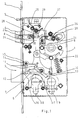
- a lock housing 1 Within a lock housing 1 are located in the FIG. 1 only the actual essential components that are necessary to explain the invention. All other components have been omitted. It will thus affect the function of the illustrated self-locking panic lock in any way.
- the left lateral conclusion of the lock housing 1 forms a face plate 2, which is broken by a control 5 of a case 4 and a bolt 3.
- a nut 9 which is equipped with a driver 21 which is connected via a rotatable connection 20 with a member 8 in operative connection. So that the nut 9, which may be a split nut, remains in its basic position, this spring is loaded by a return spring 22. Likewise, a spring 26 is present, which loads the nut 9.
- first lock cylinder 18 Within the lock housing there is a first lock cylinder 18 and a second lock cylinder 19.
- the bolt 3 is guided with its locking shaft 6 via a guide pin 11 within a gate 10, which is located in the translatory member 8.
- the gate 10 is designed obliquely and has at their ends an upper latch 12 and a lower latching 13. It is clear that by the movement of the translatory member upwards in the drawing of FIG. 1 the bolt 3 is pulled into the lock housing 1 due to the positive guidance on the guide pin 11 within the gate 10.
- case 4 The arranged above the bolt 3 case 4 is designed doppelschenkelig and in their geometrical dimensions wider than the bolt 3. Following the case 4, a case shaft 23 is present, which is loaded by a spring 24. By the spring 24, the case 4 is always pressed to the outside. In the presentation of the FIG. 1 is excluded case of bolt 3, the case 4 via a case locking member 27, ie the case 4 can not be pressed into the lock housing 1. At the same time, the double-legged trap is locked in this position. Only when the translatory member 8 moves the latch 3 into the lock housing, the latch shaft 23 is released via the latch locking member 27, so that the latch can be pressed into the lock housing 1.
- the control element 5 which is loaded by a spring 25.
- the spring 25 always pushes the control 5 out of the forend.
- the control element 5 has in the interior of the lock housing 1, a projection 29 which cooperates with a locking lug 28 which is located approximately at the end of the translatory member 8.
- the projection 29 locks with the locking lug 28 of the member 8.
- the member 8 can not sag back down into the lock housing 1, as it by the projection 29 in conjunction with the locking lug 28th held in this position.
- the control element 5 Only at the moment when the control element 5 comes into contact with a strike plate, not shown, the control element 5 is pressed into the lock housing against the spring 25. As a result, the control element 5 moves into the lock housing 1 and at the same time releases the link 8.
- the translatory member 8 is guided within the lock housing 1 by means of a guide pin 15 in an opening 14. If now causes a rotation of the locking nose over one of the lock cylinder 18 or 19 via a locking lug, not shown, this comes with a Driver 17 or a blocking lug 31, depending on the use of the lock cylinder 18 or 19, together and thus raises the member 8 at.
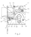
- FIG. 2 shows a partial section of the in FIG. 1 closer described self-locking panic lock. It is contrary to the FIG. 2 only the lock cylinder 18 shown, which cooperates with a blocking device 35.
- the blocking device 35 is mounted on the translatory member 8 in this embodiment.
- the blocking device 35 preferably consists of a blocking element 32, which includes either an electromagnet or a motor.
- a plunger 37 of the blocking element 32 is pivotally attached to a blocking lever 36.
- the blocking lever 36 is designed as an L-shaped lever and has the blocking lug 31 at a free end.
- the other end of the L-shaped blocking lever 36 is rotatably mounted in a pivot point 33 on the member 8.
- the blocking lug 31 is located outside the closing track 38 of the locking lug 30 of the lock cylinder 18.
- the lock shown can not be unlocked by the operation of the lock cylinder 18 in this position on the locking lug 30 in conjunction with the driver 16.
- FIG. 3 In the embodiment of FIG. 3 is in contrast to the embodiment of FIG. 2 the blocking nose 31 is retracted into the closing track 38 of the closing nose 30. This shows that the locking lug 30 coincides with the blocking lug 31 and thus an actuation of the lock via the lock cylinder 18 can take place, because by the locking lug 30, the member 8 is translationally displaced.
- the blocking device 35 can also be subsequently attached to the blocking lever 36 to the translatory member 8.
- the blocking element 32 as an electromagnet this is preferably designed bistable.
Landscapes
- Engineering & Computer Science (AREA)
- Structural Engineering (AREA)
- Business, Economics & Management (AREA)
- Emergency Management (AREA)
- Lock And Its Accessories (AREA)
Applications Claiming Priority (1)
| Application Number | Priority Date | Filing Date | Title |
|---|---|---|---|
| DE102006060449A DE102006060449A1 (de) | 2006-12-19 | 2006-12-19 | Selbstverriegelndes Panikschloss |
Publications (3)
| Publication Number | Publication Date |
|---|---|
| EP1936076A2 true EP1936076A2 (fr) | 2008-06-25 |
| EP1936076A3 EP1936076A3 (fr) | 2010-06-23 |
| EP1936076B1 EP1936076B1 (fr) | 2014-08-20 |
Family
ID=39314981
Family Applications (1)
| Application Number | Title | Priority Date | Filing Date |
|---|---|---|---|
| EP07021275.8A Not-in-force EP1936076B1 (fr) | 2006-12-19 | 2007-10-31 | Serrure anti-panique à verrouillage automatique |
Country Status (2)
| Country | Link |
|---|---|
| EP (1) | EP1936076B1 (fr) |
| DE (1) | DE102006060449A1 (fr) |
Families Citing this family (1)
| Publication number | Priority date | Publication date | Assignee | Title |
|---|---|---|---|---|
| DE102017129177B4 (de) * | 2017-12-07 | 2023-08-17 | Andreas Maier Gmbh & Co. Kg | Doppelzylinderschloss |
Citations (8)
| Publication number | Priority date | Publication date | Assignee | Title |
|---|---|---|---|---|
| CH473298A (de) | 1967-06-09 | 1969-05-31 | Fiand F Gmbh | Rechts und links verwendbares Türschloss |
| DE19630972A1 (de) | 1995-07-31 | 1997-02-06 | Talleres Escoriaza Sa | Schloß |
| DE19713752C2 (de) | 1997-04-04 | 1998-12-24 | Dorma Gmbh & Co Kg | Einsteckschloß |
| DE29905712U1 (de) | 1999-03-22 | 1999-06-02 | Hauff, Torsten, 10245 Berlin | Schloß mit Haupt- und Nebenschließung |
| DE19826869C1 (de) | 1998-06-17 | 2000-01-13 | Steinbach & Vollmann | Schloß für Hochsicherheitstüren |
| EP0882859B1 (fr) | 1997-06-05 | 2002-04-10 | Adolf Dolezel GmbH | Système de serrure et ferrure |
| DE19906271C2 (de) | 1999-02-15 | 2002-07-18 | Volker Sattler | Schloßkasten für eine Tür |
| DE10122466A1 (de) | 2001-05-09 | 2002-11-28 | Steinbach & Vollmann | Schloß |
Family Cites Families (6)
| Publication number | Priority date | Publication date | Assignee | Title |
|---|---|---|---|---|
| DE3008728A1 (de) * | 1980-03-07 | 1981-09-24 | Zeiss Ikon Ag | Durch normal- und hilfsschluessel betaetigbare schliesseinrichtung |
| DE3009166A1 (de) * | 1980-03-10 | 1981-09-24 | Scovill Sicherheitseinrichtungen Gmbh, 5620 Velbert | Tuerschloss, insbesondere einsteckschloss |
| DE19626745C1 (de) * | 1996-07-03 | 1997-10-16 | Dorma Gmbh & Co Kg | Selbstverriegelndes Panikschloß |
| DE19827516C2 (de) * | 1998-06-22 | 2000-05-18 | Dorma Gmbh & Co Kg | Selbstverriegelndes Panikschloß |
| DE19858174C2 (de) * | 1998-12-17 | 2001-05-10 | Dorma Gmbh & Co Kg | Türschloß |
| DE20300394U1 (de) * | 2003-01-10 | 2003-04-30 | Bks Gmbh, 42549 Velbert | Einsteckschloß |
-
2006
- 2006-12-19 DE DE102006060449A patent/DE102006060449A1/de not_active Withdrawn
-
2007
- 2007-10-31 EP EP07021275.8A patent/EP1936076B1/fr not_active Not-in-force
Patent Citations (8)
| Publication number | Priority date | Publication date | Assignee | Title |
|---|---|---|---|---|
| CH473298A (de) | 1967-06-09 | 1969-05-31 | Fiand F Gmbh | Rechts und links verwendbares Türschloss |
| DE19630972A1 (de) | 1995-07-31 | 1997-02-06 | Talleres Escoriaza Sa | Schloß |
| DE19713752C2 (de) | 1997-04-04 | 1998-12-24 | Dorma Gmbh & Co Kg | Einsteckschloß |
| EP0882859B1 (fr) | 1997-06-05 | 2002-04-10 | Adolf Dolezel GmbH | Système de serrure et ferrure |
| DE19826869C1 (de) | 1998-06-17 | 2000-01-13 | Steinbach & Vollmann | Schloß für Hochsicherheitstüren |
| DE19906271C2 (de) | 1999-02-15 | 2002-07-18 | Volker Sattler | Schloßkasten für eine Tür |
| DE29905712U1 (de) | 1999-03-22 | 1999-06-02 | Hauff, Torsten, 10245 Berlin | Schloß mit Haupt- und Nebenschließung |
| DE10122466A1 (de) | 2001-05-09 | 2002-11-28 | Steinbach & Vollmann | Schloß |
Also Published As
| Publication number | Publication date |
|---|---|
| DE102006060449A1 (de) | 2008-06-26 |
| EP1936076A3 (fr) | 2010-06-23 |
| EP1936076B1 (fr) | 2014-08-20 |
Similar Documents
| Publication | Publication Date | Title |
|---|---|---|
| DE102006059565B4 (de) | Schließanlage für Türen, Fenster oder dergleichen, insbesondere Treibstangenschloss mit Panikfunktion und Mehrpunktverriegelung | |
| EP1936075A2 (fr) | Serrure anti-panique électromécanique à verrouillage automatique | |
| EP2474692B2 (fr) | Dispositif de serrure de porte et procédé d'ouverture d'un dispositif de serrure de porte | |
| EP1431481B1 (fr) | Serrure | |
| EP1970507A2 (fr) | Serrure anti-panique | |
| EP1440930B1 (fr) | Serrure de porte à déverrouillage de secours | |
| EP0816603B1 (fr) | Serrure anti-panique autoverrouillante | |
| DE102017208059A1 (de) | Fenster oder Tür mit einbruchsicherer Kippöffnungsbegrenzung | |
| EP2339096B1 (fr) | Serrure à crémone dotée d'une fonction anti-panique et d'un verrouillage multiple | |
| DE19546467C1 (de) | Sicherheitsschloß | |
| DE102010028647B3 (de) | Schloss | |
| EP1936073A2 (fr) | Serrure anti-panique à verrouillage automatique | |
| EP3628801B1 (fr) | Dispositif de fermeture pour une porte et procédé pour ouvrir une porte | |
| EP0716200A1 (fr) | Dispositif de verrouillage pour portes | |
| EP1936076B1 (fr) | Serrure anti-panique à verrouillage automatique | |
| DE10122466A1 (de) | Schloß | |
| EP3748109A1 (fr) | Dispositif de verrouillage | |
| EP1936074A2 (fr) | Serrure anti-panique à verrouillage automatique, et procédé d'utilisation d'une serrure anti-panique à verrouillage automatique | |
| EP3655601B1 (fr) | Serrure | |
| DE102005001312B4 (de) | Fernbetätigter Türöffner | |
| DE19812276C1 (de) | Sicherheitsschloß | |
| EP3536882A1 (fr) | Serrure pour un battant | |
| DE102023122178A1 (de) | Automatisch verriegelndes Treibstangenschloss | |
| EP1816289A1 (fr) | Serrure | |
| EP3543437A1 (fr) | Dispositif formant serrure pourvu d'une serrure pour une porte à battants mobiles |
Legal Events
| Date | Code | Title | Description |
|---|---|---|---|
| PUAI | Public reference made under article 153(3) epc to a published international application that has entered the european phase |
Free format text: ORIGINAL CODE: 0009012 |
|
| AK | Designated contracting states |
Kind code of ref document: A2 Designated state(s): AT BE BG CH CY CZ DE DK EE ES FI FR GB GR HU IE IS IT LI LT LU LV MC MT NL PL PT RO SE SI SK TR |
|
| AX | Request for extension of the european patent |
Extension state: AL BA HR MK RS |
|
| PUAL | Search report despatched |
Free format text: ORIGINAL CODE: 0009013 |
|
| AK | Designated contracting states |
Kind code of ref document: A3 Designated state(s): AT BE BG CH CY CZ DE DK EE ES FI FR GB GR HU IE IS IT LI LT LU LV MC MT NL PL PT RO SE SI SK TR |
|
| AX | Request for extension of the european patent |
Extension state: AL BA HR MK RS |
|
| RAP1 | Party data changed (applicant data changed or rights of an application transferred) |
Owner name: DORMA GMBH + CO. KG |
|
| 17P | Request for examination filed |
Effective date: 20101223 |
|
| AKX | Designation fees paid |
Designated state(s): AT BE BG CH CY CZ DE DK EE ES FI FR GB GR HU IE IS IT LI LT LU LV MC MT NL PL PT RO SE SI SK TR |
|
| RIC1 | Information provided on ipc code assigned before grant |
Ipc: E05B 65/10 20060101ALI20140306BHEP Ipc: E05B 63/20 20060101ALI20140306BHEP Ipc: E05B 35/10 20060101ALN20140306BHEP Ipc: E05B 59/00 20060101ALI20140306BHEP Ipc: E05B 35/08 20060101AFI20140306BHEP Ipc: E05B 47/06 20060101ALN20140306BHEP |
|
| GRAP | Despatch of communication of intention to grant a patent |
Free format text: ORIGINAL CODE: EPIDOSNIGR1 |
|
| INTG | Intention to grant announced |
Effective date: 20140425 |
|
| GRAS | Grant fee paid |
Free format text: ORIGINAL CODE: EPIDOSNIGR3 |
|
| GRAA | (expected) grant |
Free format text: ORIGINAL CODE: 0009210 |
|
| AK | Designated contracting states |
Kind code of ref document: B1 Designated state(s): AT BE BG CH CY CZ DE DK EE ES FI FR GB GR HU IE IS IT LI LT LU LV MC MT NL PL PT RO SE SI SK TR |
|
| REG | Reference to a national code |
Ref country code: GB Ref legal event code: FG4D Free format text: NOT ENGLISH |
|
| REG | Reference to a national code |
Ref country code: CH Ref legal event code: EP |
|
| REG | Reference to a national code |
Ref country code: AT Ref legal event code: REF Ref document number: 683580 Country of ref document: AT Kind code of ref document: T Effective date: 20140915 |
|
| REG | Reference to a national code |
Ref country code: IE Ref legal event code: FG4D Free format text: LANGUAGE OF EP DOCUMENT: GERMAN |
|
| REG | Reference to a national code |
Ref country code: DE Ref legal event code: R096 Ref document number: 502007013374 Country of ref document: DE Effective date: 20141002 |
|
| REG | Reference to a national code |
Ref country code: NL Ref legal event code: VDEP Effective date: 20140820 |
|
| REG | Reference to a national code |
Ref country code: LT Ref legal event code: MG4D |
|
| PG25 | Lapsed in a contracting state [announced via postgrant information from national office to epo] |
Ref country code: PT Free format text: LAPSE BECAUSE OF FAILURE TO SUBMIT A TRANSLATION OF THE DESCRIPTION OR TO PAY THE FEE WITHIN THE PRESCRIBED TIME-LIMIT Effective date: 20141222 Ref country code: SE Free format text: LAPSE BECAUSE OF FAILURE TO SUBMIT A TRANSLATION OF THE DESCRIPTION OR TO PAY THE FEE WITHIN THE PRESCRIBED TIME-LIMIT Effective date: 20140820 Ref country code: GR Free format text: LAPSE BECAUSE OF FAILURE TO SUBMIT A TRANSLATION OF THE DESCRIPTION OR TO PAY THE FEE WITHIN THE PRESCRIBED TIME-LIMIT Effective date: 20141121 Ref country code: ES Free format text: LAPSE BECAUSE OF FAILURE TO SUBMIT A TRANSLATION OF THE DESCRIPTION OR TO PAY THE FEE WITHIN THE PRESCRIBED TIME-LIMIT Effective date: 20140820 Ref country code: FI Free format text: LAPSE BECAUSE OF FAILURE TO SUBMIT A TRANSLATION OF THE DESCRIPTION OR TO PAY THE FEE WITHIN THE PRESCRIBED TIME-LIMIT Effective date: 20140820 Ref country code: LT Free format text: LAPSE BECAUSE OF FAILURE TO SUBMIT A TRANSLATION OF THE DESCRIPTION OR TO PAY THE FEE WITHIN THE PRESCRIBED TIME-LIMIT Effective date: 20140820 Ref country code: BG Free format text: LAPSE BECAUSE OF FAILURE TO SUBMIT A TRANSLATION OF THE DESCRIPTION OR TO PAY THE FEE WITHIN THE PRESCRIBED TIME-LIMIT Effective date: 20141120 |
|
| PG25 | Lapsed in a contracting state [announced via postgrant information from national office to epo] |
Ref country code: IS Free format text: LAPSE BECAUSE OF FAILURE TO SUBMIT A TRANSLATION OF THE DESCRIPTION OR TO PAY THE FEE WITHIN THE PRESCRIBED TIME-LIMIT Effective date: 20141220 Ref country code: LV Free format text: LAPSE BECAUSE OF FAILURE TO SUBMIT A TRANSLATION OF THE DESCRIPTION OR TO PAY THE FEE WITHIN THE PRESCRIBED TIME-LIMIT Effective date: 20140820 |
|
| PG25 | Lapsed in a contracting state [announced via postgrant information from national office to epo] |
Ref country code: NL Free format text: LAPSE BECAUSE OF FAILURE TO SUBMIT A TRANSLATION OF THE DESCRIPTION OR TO PAY THE FEE WITHIN THE PRESCRIBED TIME-LIMIT Effective date: 20140820 |
|
| REG | Reference to a national code |
Ref country code: DE Ref legal event code: R081 Ref document number: 502007013374 Country of ref document: DE Owner name: DORMAKABA DEUTSCHLAND GMBH, DE Free format text: FORMER OWNER: DORMA GMBH + CO. KG, 58256 ENNEPETAL, DE Effective date: 20150224 Ref country code: DE Ref legal event code: R081 Ref document number: 502007013374 Country of ref document: DE Owner name: DORMA DEUTSCHLAND GMBH, DE Free format text: FORMER OWNER: DORMA GMBH + CO. KG, 58256 ENNEPETAL, DE Effective date: 20150224 |
|
| PG25 | Lapsed in a contracting state [announced via postgrant information from national office to epo] |
Ref country code: EE Free format text: LAPSE BECAUSE OF FAILURE TO SUBMIT A TRANSLATION OF THE DESCRIPTION OR TO PAY THE FEE WITHIN THE PRESCRIBED TIME-LIMIT Effective date: 20140820 Ref country code: CZ Free format text: LAPSE BECAUSE OF FAILURE TO SUBMIT A TRANSLATION OF THE DESCRIPTION OR TO PAY THE FEE WITHIN THE PRESCRIBED TIME-LIMIT Effective date: 20140820 Ref country code: RO Free format text: LAPSE BECAUSE OF FAILURE TO SUBMIT A TRANSLATION OF THE DESCRIPTION OR TO PAY THE FEE WITHIN THE PRESCRIBED TIME-LIMIT Effective date: 20140820 Ref country code: IT Free format text: LAPSE BECAUSE OF FAILURE TO SUBMIT A TRANSLATION OF THE DESCRIPTION OR TO PAY THE FEE WITHIN THE PRESCRIBED TIME-LIMIT Effective date: 20140820 Ref country code: DK Free format text: LAPSE BECAUSE OF FAILURE TO SUBMIT A TRANSLATION OF THE DESCRIPTION OR TO PAY THE FEE WITHIN THE PRESCRIBED TIME-LIMIT Effective date: 20140820 Ref country code: SK Free format text: LAPSE BECAUSE OF FAILURE TO SUBMIT A TRANSLATION OF THE DESCRIPTION OR TO PAY THE FEE WITHIN THE PRESCRIBED TIME-LIMIT Effective date: 20140820 |
|
| REG | Reference to a national code |
Ref country code: DE Ref legal event code: R097 Ref document number: 502007013374 Country of ref document: DE |
|
| PG25 | Lapsed in a contracting state [announced via postgrant information from national office to epo] |
Ref country code: MC Free format text: LAPSE BECAUSE OF FAILURE TO SUBMIT A TRANSLATION OF THE DESCRIPTION OR TO PAY THE FEE WITHIN THE PRESCRIBED TIME-LIMIT Effective date: 20140820 Ref country code: LU Free format text: LAPSE BECAUSE OF FAILURE TO SUBMIT A TRANSLATION OF THE DESCRIPTION OR TO PAY THE FEE WITHIN THE PRESCRIBED TIME-LIMIT Effective date: 20141031 Ref country code: PL Free format text: LAPSE BECAUSE OF FAILURE TO SUBMIT A TRANSLATION OF THE DESCRIPTION OR TO PAY THE FEE WITHIN THE PRESCRIBED TIME-LIMIT Effective date: 20140820 |
|
| REG | Reference to a national code |
Ref country code: CH Ref legal event code: PL |
|
| PLBE | No opposition filed within time limit |
Free format text: ORIGINAL CODE: 0009261 |
|
| STAA | Information on the status of an ep patent application or granted ep patent |
Free format text: STATUS: NO OPPOSITION FILED WITHIN TIME LIMIT |
|
| PG25 | Lapsed in a contracting state [announced via postgrant information from national office to epo] |
Ref country code: BE Free format text: LAPSE BECAUSE OF NON-PAYMENT OF DUE FEES Effective date: 20141031 |
|
| 26N | No opposition filed |
Effective date: 20150521 |
|
| GBPC | Gb: european patent ceased through non-payment of renewal fee |
Effective date: 20141120 |
|
| REG | Reference to a national code |
Ref country code: IE Ref legal event code: MM4A |
|
| PG25 | Lapsed in a contracting state [announced via postgrant information from national office to epo] |
Ref country code: CH Free format text: LAPSE BECAUSE OF NON-PAYMENT OF DUE FEES Effective date: 20141031 Ref country code: LI Free format text: LAPSE BECAUSE OF NON-PAYMENT OF DUE FEES Effective date: 20141031 |
|
| REG | Reference to a national code |
Ref country code: FR Ref legal event code: ST Effective date: 20150630 |
|
| PG25 | Lapsed in a contracting state [announced via postgrant information from national office to epo] |
Ref country code: FR Free format text: LAPSE BECAUSE OF NON-PAYMENT OF DUE FEES Effective date: 20141031 |
|
| PG25 | Lapsed in a contracting state [announced via postgrant information from national office to epo] |
Ref country code: GB Free format text: LAPSE BECAUSE OF NON-PAYMENT OF DUE FEES Effective date: 20141120 Ref country code: IE Free format text: LAPSE BECAUSE OF NON-PAYMENT OF DUE FEES Effective date: 20141031 |
|
| PG25 | Lapsed in a contracting state [announced via postgrant information from national office to epo] |
Ref country code: SI Free format text: LAPSE BECAUSE OF FAILURE TO SUBMIT A TRANSLATION OF THE DESCRIPTION OR TO PAY THE FEE WITHIN THE PRESCRIBED TIME-LIMIT Effective date: 20140820 |
|
| REG | Reference to a national code |
Ref country code: AT Ref legal event code: MM01 Ref document number: 683580 Country of ref document: AT Kind code of ref document: T Effective date: 20141031 |
|
| PG25 | Lapsed in a contracting state [announced via postgrant information from national office to epo] |
Ref country code: AT Free format text: LAPSE BECAUSE OF NON-PAYMENT OF DUE FEES Effective date: 20141031 |
|
| PG25 | Lapsed in a contracting state [announced via postgrant information from national office to epo] |
Ref country code: CY Free format text: LAPSE BECAUSE OF FAILURE TO SUBMIT A TRANSLATION OF THE DESCRIPTION OR TO PAY THE FEE WITHIN THE PRESCRIBED TIME-LIMIT Effective date: 20140820 |
|
| PG25 | Lapsed in a contracting state [announced via postgrant information from national office to epo] |
Ref country code: TR Free format text: LAPSE BECAUSE OF FAILURE TO SUBMIT A TRANSLATION OF THE DESCRIPTION OR TO PAY THE FEE WITHIN THE PRESCRIBED TIME-LIMIT Effective date: 20140820 Ref country code: HU Free format text: LAPSE BECAUSE OF FAILURE TO SUBMIT A TRANSLATION OF THE DESCRIPTION OR TO PAY THE FEE WITHIN THE PRESCRIBED TIME-LIMIT; INVALID AB INITIO Effective date: 20071031 Ref country code: MT Free format text: LAPSE BECAUSE OF FAILURE TO SUBMIT A TRANSLATION OF THE DESCRIPTION OR TO PAY THE FEE WITHIN THE PRESCRIBED TIME-LIMIT Effective date: 20140820 |
|
| REG | Reference to a national code |
Ref country code: DE Ref legal event code: R082 Ref document number: 502007013374 Country of ref document: DE Representative=s name: BALDER IP LAW, S.L., ES Ref country code: DE Ref legal event code: R081 Ref document number: 502007013374 Country of ref document: DE Owner name: DORMAKABA DEUTSCHLAND GMBH, DE Free format text: FORMER OWNER: DORMA DEUTSCHLAND GMBH, 58256 ENNEPETAL, DE |
|
| PGFP | Annual fee paid to national office [announced via postgrant information from national office to epo] |
Ref country code: DE Payment date: 20221019 Year of fee payment: 16 |
|
| REG | Reference to a national code |
Ref country code: DE Ref legal event code: R119 Ref document number: 502007013374 Country of ref document: DE |
|
| PG25 | Lapsed in a contracting state [announced via postgrant information from national office to epo] |
Ref country code: DE Free format text: LAPSE BECAUSE OF NON-PAYMENT OF DUE FEES Effective date: 20240501 |