EP1936131B1 - Stützstruktur für eine Nockenwelle sowie Verfahren zur Montage und Herstellung einer Nockenwelle - Google Patents
Stützstruktur für eine Nockenwelle sowie Verfahren zur Montage und Herstellung einer Nockenwelle Download PDFInfo
- Publication number
- EP1936131B1 EP1936131B1 EP07021948A EP07021948A EP1936131B1 EP 1936131 B1 EP1936131 B1 EP 1936131B1 EP 07021948 A EP07021948 A EP 07021948A EP 07021948 A EP07021948 A EP 07021948A EP 1936131 B1 EP1936131 B1 EP 1936131B1
- Authority
- EP
- European Patent Office
- Prior art keywords
- bearing
- shaft body
- cam lobe
- camshaft
- cam
- Prior art date
- Legal status (The legal status is an assumption and is not a legal conclusion. Google has not performed a legal analysis and makes no representation as to the accuracy of the status listed.)
- Revoked
Links
- 238000000034 method Methods 0.000 title claims description 10
- 238000004519 manufacturing process Methods 0.000 title description 2
- 238000003466 welding Methods 0.000 claims description 5
- 230000000149 penetrating effect Effects 0.000 description 8
- 125000006850 spacer group Chemical group 0.000 description 8
- 210000001331 nose Anatomy 0.000 description 7
- 230000003014 reinforcing effect Effects 0.000 description 5
- 238000010438 heat treatment Methods 0.000 description 3
- 229910000838 Al alloy Inorganic materials 0.000 description 2
- XEEYBQQBJWHFJM-UHFFFAOYSA-N Iron Chemical compound [Fe] XEEYBQQBJWHFJM-UHFFFAOYSA-N 0.000 description 2
- 230000000694 effects Effects 0.000 description 2
- 239000007769 metal material Substances 0.000 description 2
- TZRXHJWUDPFEEY-UHFFFAOYSA-N Pentaerythritol Tetranitrate Chemical compound [O-][N+](=O)OCC(CO[N+]([O-])=O)(CO[N+]([O-])=O)CO[N+]([O-])=O TZRXHJWUDPFEEY-UHFFFAOYSA-N 0.000 description 1
- 229910000831 Steel Inorganic materials 0.000 description 1
- 238000005266 casting Methods 0.000 description 1
- 238000003780 insertion Methods 0.000 description 1
- 230000037431 insertion Effects 0.000 description 1
- 230000002452 interceptive effect Effects 0.000 description 1
- 229910052742 iron Inorganic materials 0.000 description 1
- 238000012986 modification Methods 0.000 description 1
- 230000004048 modification Effects 0.000 description 1
- 239000010959 steel Substances 0.000 description 1
Images




Classifications
-
- F—MECHANICAL ENGINEERING; LIGHTING; HEATING; WEAPONS; BLASTING
- F01—MACHINES OR ENGINES IN GENERAL; ENGINE PLANTS IN GENERAL; STEAM ENGINES
- F01L—CYCLICALLY OPERATING VALVES FOR MACHINES OR ENGINES
- F01L1/00—Valve-gear or valve arrangements, e.g. lift-valve gear
- F01L1/02—Valve drive
- F01L1/04—Valve drive by means of cams, camshafts, cam discs, eccentrics or the like
- F01L1/047—Camshafts
- F01L1/053—Camshafts overhead type
-
- B—PERFORMING OPERATIONS; TRANSPORTING
- B21—MECHANICAL METAL-WORKING WITHOUT ESSENTIALLY REMOVING MATERIAL; PUNCHING METAL
- B21D—WORKING OR PROCESSING OF SHEET METAL OR METAL TUBES, RODS OR PROFILES WITHOUT ESSENTIALLY REMOVING MATERIAL; PUNCHING METAL
- B21D53/00—Making other particular articles
- B21D53/84—Making other particular articles other parts for engines, e.g. connecting-rods
- B21D53/845—Making camshafts
-
- F—MECHANICAL ENGINEERING; LIGHTING; HEATING; WEAPONS; BLASTING
- F01—MACHINES OR ENGINES IN GENERAL; ENGINE PLANTS IN GENERAL; STEAM ENGINES
- F01L—CYCLICALLY OPERATING VALVES FOR MACHINES OR ENGINES
- F01L1/00—Valve-gear or valve arrangements, e.g. lift-valve gear
- F01L1/02—Valve drive
- F01L1/04—Valve drive by means of cams, camshafts, cam discs, eccentrics or the like
- F01L1/047—Camshafts
-
- F—MECHANICAL ENGINEERING; LIGHTING; HEATING; WEAPONS; BLASTING
- F01—MACHINES OR ENGINES IN GENERAL; ENGINE PLANTS IN GENERAL; STEAM ENGINES
- F01L—CYCLICALLY OPERATING VALVES FOR MACHINES OR ENGINES
- F01L1/00—Valve-gear or valve arrangements, e.g. lift-valve gear
- F01L1/02—Valve drive
- F01L1/04—Valve drive by means of cams, camshafts, cam discs, eccentrics or the like
- F01L1/047—Camshafts
- F01L2001/0476—Camshaft bearings
-
- Y—GENERAL TAGGING OF NEW TECHNOLOGICAL DEVELOPMENTS; GENERAL TAGGING OF CROSS-SECTIONAL TECHNOLOGIES SPANNING OVER SEVERAL SECTIONS OF THE IPC; TECHNICAL SUBJECTS COVERED BY FORMER USPC CROSS-REFERENCE ART COLLECTIONS [XRACs] AND DIGESTS
- Y10—TECHNICAL SUBJECTS COVERED BY FORMER USPC
- Y10T—TECHNICAL SUBJECTS COVERED BY FORMER US CLASSIFICATION
- Y10T29/00—Metal working
- Y10T29/49—Method of mechanical manufacture
- Y10T29/49229—Prime mover or fluid pump making
- Y10T29/49293—Camshaft making
Definitions
- the present invention relates to a supporting structure for a camshaft, as well as methods for mounting and manufacturing a camshaft.
- the above-mentioned conventional bearing has been having a problem that, when the cap is fitted into the cam housing, the center of axle of the semi-circular arc shaped concave portion in the cap side and the center of axle of the semi-circular arc shaped concave portion in the cam housing would be out of alignment due to dimension tolerance and fitting tolerance. As a result, smooth rotation of the camshaft would have been in danger of disturbance.
- the patent application DE 198 31 772 A1 discloses a cylinder head having a camshaft casing, in which there are cylindrical borings in spaced parallel webs, either in the casing itself or in the casing cover, to form the bearing points for at
- camshaft the cams of which are larger than the borings.
- bearing elements in the bearing points, which are fixed to the cams so that they cannot turn relative to them.
- the camshaft casing has a cover.
- the camshaft consists of parts which can be fitted together in the cylinder head.
- This invention has been completed based on the above situation, and its purpose is to provide a supporting structure of a camshaft which does not disturb smooth rotation of the camshaft.
- the present invention provides a method for mounting a camshaft to a supporting member, wherein the method comprises the steps of:
- said cam lobe includes a cam nose and the step of positioning said cam lobe is performed by using a predetermined jig such that said cam nose is facing to a prescribed direction.
- a bearing member uniting two concave portions in a semi-circular arc shape so as to form a circular shape might disturb smooth rotation of a camshaft since the center of axle of the two concave portions in a semi-circular arc shape would be out of alignment.
- a cam lobe is formed as a single part, not being integrally formed with a shaft body.
- a mounting hole is provided in the cam lobe for allowing the shaft body to penetrate through.
- the shaft body penetrates through a plurality of bearing holes, as well as a mounting hole provided in the cam lobe arranged in between the adjacent bearing holes.
- the bearing hole in a perfect circular shape can be achieved since there is no need to divide the bearing member into two semi-circular arc shaped concave portions. Consequently, the cam shaft can be supported by the bearing member so that it is rotated smoothly.
- the external diameter of the part of the shaft body which fits with the bearing hole needs to be larger than the external diameter of the cam lobe, since the cam lobe needs to penetrate through the bearing hole. Therefore, the bearing structure for supporting the camshaft needs to grow in size.
- the cam lobe there is no need for the cam lobe to penetrate through the bearing hole, since the cam lobe is a single part, not formed integrally with the shaft body. Hence, it is possible to make the external diameter of the bearing hole smaller, thereby enabling downsizing of the bearing structure.
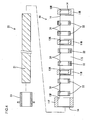
- Embodiment 1 of the present invention is described as referring to Figs. 1 to 5 .
- a supporting member 10 is a single part made of metallic material such as aluminum alloy.
- the supporting member 10 comprised of a pair of right and left side frames 11S, a front frame 11F connecting the side frames 11S at their front ends, a rear frame 11 R connecting the side frames 11S at their rear ends, and a pair of front and rear middle frames 11M dividing the area surrounded by the side frames 11S, the front frame 11 F, and the rear frame 11 R into three in an anteroposterior direction.
- Bolt-holes 12 penetrating through in vertical direction are formed respectively in the front frame 11F, the rear frame 11R, and the pair of middle frames 11M.
- the bolt-holes 12 are formed in three places in each of the frames: at both right and left ends, as well as at the center in horizontal direction.
- the supporting member 10 is fixed onto the top surface of a cylinder head not shown.
- the supporting member 10 is fixed onto the top surface of the cylinder head with a bolt (not shown) inserted into the bolt-hole 12.
- Circular bearing holes 13F, 13M, and 13R penetrating through the interval portion of the adjacent bolt-holes 12 in an anteroposterior direction are formed respectively in the front frame 11F, the rear frame 11R, and the pair of middle frames 11M.
- the circular bearing holes 13F, 13M, and 13R are formed in pairs in horizontal direction.
- the four bearing holes 13F, 13M, and 13R in the right side are concentrically aligned.
- the four bearing holes 13F, 13M, and 13R in the left side are also concentrically aligned.
- the internal diameter of the bearing hole 13F formed in the front frame 11F is larger than those of the bearing holes 13M and 13R formed respectively in the middle frame 11M and the rear frame 11R.
- the internal diameter of the bearing holes 13M formed in the middle frames 11M is the same as that of the bearing hole 13R formed in the rear frame 11R.
- a guide surface 14 in a tapered shape is formed (see Fig. 3 ).
- the thickness of the front frame 11F in an anteroposterior direction is greater than those of the middle frames 11M and the rear frame 11R in an anteroposterior direction.
- Each of the front frame 11F, the middle frames 11M, and the rear frame 11R configures a bearing means (bearing part).
- Two camshafts 20 are mounted in the supporting member 10.
- Each camshaft 20 is comprised of a shaft body 21, six cam lobes 22, and a spacer 23 (see Fig. 3 ).
- the shaft body 21 has a circular cross-section shape.
- the shaft body 21 has a constant external diameter at least in the area from the front end to the rear end of the supporting member 10.
- the external diameter of the shaft body 21 is slightly smaller than the internal diameter of the bearing holes 13M and 13R formed respectively in the middle frame 11M and the rear frame 11R. This size gap enables securing the clearance during insertion of the shaft body 21 into the bearing holes 13M and 13R. And thus, this clearance enables smoothly and rotatably supporting the shaft body 21 without rattling in a radial direction.
- the spacer 23 is cylindrically-shaped.
- the spacer 23 is fitted into, as well as integrally fixed to, the bearing hole 13F formed in the front frame 11F.
- the spacer 23 is fixed to the bearing hole 13F such that it cannot move both in radial and axial directions.
- the internal diameter of the spacer 23 is the same as those of the bearing holes 13M and 13R formed respectively in the middle frame 11M and the rear frame 11R.
- the cam lobe 22 has a nearly oval shape as a whole.
- a circular mounting hole 24 is formed in the cam lobe 22, penetrating through in an anteroposterior direction.
- the shape of the cam lobe 22 is similar to those of well-known cam lobes.
- the internal diameter of the mounting hole 24 is nearly the same as the external diameter of the shaft body 21.
- the shaft body 21 is penetrating through the mounting hole 24.
- the cam lobe 22 is comprised of a cam base in a circular arc shape being concentric with the mounting hole 24 and a cam nose having a longer distance from the center of the mounting hole 24 to the circumferential surface than that of the cam base.
- the maximum distance from the center of the mounting hole 24 to the circumference of the cam nose is longer than the radius of the bearing hole 13F formed in the front frame 11F. In other words, the cam lobe 22 cannot pass through any of the bearing holes 13F, 13M and 13R.
- the camshaft 20 is mounted, and at the same time, built up in the supporting member 10. These assemblings are completed in one process.
- a jig not shown which has a groove in a shape corresponding to the direction of each of the cam noses, is used, since the directions of the cam noses in each of the cam lobes 22 are individually different.
- Each of the cam lobes 22 fitted in the groove of the jig are respectively positioned such that their cam noses are facing to the prescribed directions. Moreover, they are respectively positioned such that the center of axle of the mounting hole 24 provided in the cam lobe 22 coincides with those of the bearing holes 13F, 13M, and 13R.
- each cam lobe 22 in an anteroposterior (axial) direction is fixed with the jig.
- a jig vertically nipping the cam lobe 22 may be used as the jig.
- An escaping part for avoiding interfering with the shaft body 21 is formed in the jig.
- the shaft body 21 sequentially penetrates through the bearing holes 13F, 13M, and 13R in the supporting member 10, as well as the mounting holes 24 in the cam lobes 22.
- the spacer 23 is fitted to the bearing hole 13F in the front frame 11F.
- the front end of the shaft body 21 is rotatably fitted inside of the spacer 23.
- the shaft body 21 penetrates through the bearing holes 13F, 13M, and 13R, the spacer 23, and the mounting holes 24, before each of the cam lobes 22 is fixed to the shaft body 21.
- each of the cam lobes 22 is fixed to the shaft body 21 so that the cam lobes 22 are integrally rotatable along with the shaft body 21.
- an heating means is provided to the jig. This enables heating the cam lobe 22 prior to penetrating the shaft body 21 through the mounting hole 24.
- the internal diameter of the mounting hole 24 is enlarged by heating the cam lobe 22.
- the cam lobe 22 heated, the shaft body 21 at normal temperature penetrates through the mounting hole 24.
- the cam lobe 22 is brought back to the normal temperature.
- the internal diameter of the mounting hole 24 contracts. This allows the inner circumference of the mounting hole 24 to tightly adhere to the outer circumference of the shaft body 21. With this friction on the adhering surface, the cam lobe 22 can be rigidly fixed to the shaft body 21.
- the cam lobe 22 is fixed to the shaft body 21 as described above, before the jig is removed from the cam lobe 22.
- the supporting structure of the camshaft according to the present invention brings about the effect as follows.
- a bearing member combining two semi-circular arc shaped concave portions so as to produce a circular shape might disturb a smooth rotation of a camshaft due to the misalignment of the center of axle of the two semi-circular arc shaped concave portions.
- the cam lobe 22 is formed as a single part, not formed integrally with a shaft body 21.
- a mounting hole 24 is provided in the cam lobe 22 for allowing the shaft body 21 to penetrate there through.
- the shaft body 21 penetrates through four bearing holes 13F, 13M, and 13R, and mounting holes 24 arranged in between adjacent bearing holes 13F, 13M, and 13R.
- the bearing holes 13F, 13M, and 13R each in a perfect circular shape can be achieved, since there is no need to divide the bearing holes 13F, 13M, and 13R into two semi-circular arc shaped concave portions. Consequently, the camshaft 20 can be supported with the bearing holes 13F, 13M, and 13R so as to rotate smoothly.
- the external diameter of the part of the shaft body which fits with the bearing hole needs to be larger than the external diameter of the cam lobe, since the cam lobe needs to penetrate through the bearing hole. Therefore, the bearing structure for supporting the camshaft needs to grow in size.
- the cam lobe 22 there is no need for the cam lobe 22 to penetrate through the bearing holes 13F, 13M, and 13R, since the cam lobe 22 is a single part, not formed integrally with the shaft body 21. Hence, it is possible to make the external diameter of the bearing holes 13F, 13M, and 13R smaller, thereby enabling downsizing of the bearing structure.
- a supporting member 30 has a different structure from that in the above Embodiment 1. Since the other structures are the same as those in Embodiment 1, the same reference numbers are allotted to those of the corresponding structures, omitting descriptions on constitution, working, and effect.
- the supporting member 30 in Embodiment 2 is comprised of four bearing bodies 31 and 32.
- the supporting member 30 supports two camshafts.
- Four bearing bodies 31 and 32 are placed in parallel in an anteroposterior direction, fixed to a cylinder head 50.
- bearing bodies 31 and 32 are made of aluminum alloy.
- the bearing body 31 placed in the very front corresponds to the front frame 11F in Embodiment 1.
- the remaining three bearing bodies 32 correspond to two middle frames 11M and the rear frame 11R in Embodiment 1.
- Bearing bodies 31 and 32 respectively have circular bearing holes 33 and 34 in pair which penetrate through each of the bearing bodies 31 and 32 in an anteroposterior direction.
- Bearing bodies 31 and 32 are comprised respectively of a pair of bearing parts 35, a connecting part 36 connecting the pair of bearing parts 35, and an ear 37 protruding from the circumference of the pair of bearing parts 35 to the opposite direction of the connecting part 36.
- the bearing part 35 is formed in a cylindrical shape, concentric with the bearing holes 33 and 34.
- a bolt-hole 38 is formed in the connecting part 36, penetrating vertically there through.
- These four bearing bodies 31 and 32 are mounted onto the top surface of the cylinder head 50, aligned in an anteroposterior direction. These four bearing bodies 31 and 32 are mounted such that the bearing holes 33 and 34 are on one and the same axis.
- the bearing bodies 31 and 32 are mounted with a bolt (not shown) inserted into the bolt hole 38, then screwed into a female screw hole 51 in the cylinder head 50.
- a projecting portion 39 is formed, projecting downwards.
- the bottom surface of the projecting portion 39 is contacting with the top surface of a receiving portion 52 in the cylinder head 50.
- the above-mentioned female screw hole 51 is formed in the receiving portion 52.
- the bottom surface of the ear 37 is contacting with the upper end of an upstanding portion 53 in the cylinder head 50.
- a positioning groove 54 opening upward is formed at the upper end of the upstanding portion 53.
- the ear 37 is fitting with the positioning groove 54 with its anteroposterior movement restricted.
- the bearing bodies 31 and 32 are mounted to the cylinder head 50 with only a bolt. Also, the both left and right ends of the bearing bodies 31 and 32 are merely placed onto the top surface of the cylinder head 50.
- the connecting part 36 might be deformed when a reaction force from an engine valve not shown affected the cam lobe 22. Moreover, the bearing part 35 might be lifted up due to the reaction force from the engine valve.
- a reinforcing member 40 made of a metallic material (e.g. iron and steel) having rigidity higher than those of the bearing bodies 31 and 32 is embedded inside the connecting part 36.
- the connecting part 36 includes a bolted part and a part extending from the bolted part into left and right sides, continuing to the bearing part 35.
- the reinforcing member 40 is embedded inside the connecting part 36 by metallic casting. This enables increase of the rigidity of the connecting part 36, preventing deformation and curvature of the connecting part 36 caused from the reaction force, which is coming from downside and affecting the cam lobe 22.
- a continuous hole 41 which is coaxial with the bolt hole 18 and having the same circumference as the same is formed. Therefore, no trouble occurs when a bole is inserted into the bolt hole 38.
- bearing bodies 31 and 32 are respectively fixed alone to cylinder head 50
- the bearing bodies 31 and 32 may be united each other with members other than the cylinder head 50.
Landscapes
- Engineering & Computer Science (AREA)
- Mechanical Engineering (AREA)
- General Engineering & Computer Science (AREA)
- Valve-Gear Or Valve Arrangements (AREA)
Claims (2)
- Verfahren zum Montieren einer Nockenwelle (20) an einem Stütz- bzw. Trägerglied (10), wobei das Verfahren die Schritte umfasst:Bereitstellen der Nockenwelle (20), die einen Wellenkörper (21) mit kreisförmigem Querschnitt und eine Nockenerhebung (22) umfasst, wobei die Nokkenerhebung (22) ein einzelnes Teil ist, das nicht integral mit dem Wellenkörper (21) gebildet ist, und ein Montageloch (24) aufweist, um dem Wellenkörper (21) zu erlauben, durch dieses zu penetrieren,Bereitstellen des Stütz- bzw. Trägerglieds (10), das eine Mehrzahl kreisförmiger Lagerlöcher (13F, 13M, 13R) aufweist, die auf ein und derselben Achse angeordnet sind,Positionieren der Nockenerhebung (22) zwischen den angrenzenden bzw. benachbarten Lagerlöchern (13F, 13M, 13R),dadurch gekennzeichnet, dassder Wellenkörper nach dem Positionierschritt durch die Mehrzahl von Lagerlöchern (13F, 13M, 13R), die in dem Stütz- bzw. Trägerglied (10) vorgesehen sind, und das Montageloch (24) penetriert, das in der Nockenerhebung (22) vorgesehen ist, unddie Nockenerhebung durch Schrumpfpassen bzw. -verbinden oder Schweißen integral an dem Wellenkörper befestigt bzw. fixiert ist.
- Verfahren nach Anspruch 1,
wobei die Nockenerhebung (22) eine Nockennase enthält und
wobei der Schritt des Positionierens der Nockenerhebung (22) unter Verwendung eines vorbestimmten Werkzeugs durchgeführt wird, so dass die Nokkennase in eine vorgeschriebene Richtung zeigt.
Applications Claiming Priority (1)
| Application Number | Priority Date | Filing Date | Title |
|---|---|---|---|
| JP2006344513A JP2008157062A (ja) | 2006-12-21 | 2006-12-21 | カムシャフトの支持構造、カムシャフトの取付け方法及びカムシャフトの製造方法 |
Publications (2)
| Publication Number | Publication Date |
|---|---|
| EP1936131A1 EP1936131A1 (de) | 2008-06-25 |
| EP1936131B1 true EP1936131B1 (de) | 2010-10-13 |
Family
ID=39272876
Family Applications (1)
| Application Number | Title | Priority Date | Filing Date |
|---|---|---|---|
| EP07021948A Revoked EP1936131B1 (de) | 2006-12-21 | 2007-11-12 | Stützstruktur für eine Nockenwelle sowie Verfahren zur Montage und Herstellung einer Nockenwelle |
Country Status (5)
| Country | Link |
|---|---|
| US (1) | US7775186B2 (de) |
| EP (1) | EP1936131B1 (de) |
| JP (1) | JP2008157062A (de) |
| AT (1) | ATE484654T1 (de) |
| DE (1) | DE602007009780D1 (de) |
Cited By (1)
| Publication number | Priority date | Publication date | Assignee | Title |
|---|---|---|---|---|
| DE102019214289A1 (de) * | 2019-09-19 | 2021-03-25 | Volkswagen Aktiengesellschaft | Nockenwellenanordnung für ein Kraftfahrzeug und Verfahren zum Zusammenbau einer Nockenwellenanordnung |
Families Citing this family (30)
| Publication number | Priority date | Publication date | Assignee | Title |
|---|---|---|---|---|
| DE102007024092A1 (de) * | 2007-05-22 | 2008-11-27 | Mahle International Gmbh | Nockenwelle |
| US7975381B2 (en) * | 2008-09-10 | 2011-07-12 | Ford Global Technologies | Valve operating camshaft system for internal combustion engine |
| DE102008062187A1 (de) | 2008-12-13 | 2010-06-17 | Volkswagen Ag | Brennkraftmaschine mit zwei Nockenwellen |
| DE102008064194A1 (de) * | 2008-12-22 | 2010-07-01 | Usk Karl Utz Sondermaschinen Gmbh | Verfahren und Vorrichtung zur Positionierung mehrerer Funktionselemente in einer vorbestimmten Winkelposition auf einer Welle |
| GB2467334A (en) * | 2009-01-30 | 2010-08-04 | Mechadyne Plc | Assembled camshaft for i.c. engines |
| SE538122C2 (sv) * | 2010-05-11 | 2016-03-08 | Agap Hb | Kamaxel med demonterbart lagerläge |
| DE102010045047A1 (de) * | 2010-09-10 | 2012-03-15 | Thyssenkrupp Presta Teccenter Ag | Verfahren zum Zusammenbau eines Motormoduls |
| DE102011011803A1 (de) * | 2011-02-19 | 2012-08-23 | Volkswagen Ag | Betätigungsmodul für mindestens ein Gaswechselventil einer Brennkraftmaschine |
| DE102011001123A1 (de) * | 2011-03-07 | 2012-09-13 | Dr. Ing. H.C. F. Porsche Aktiengesellschaft | Brennkraftmaschine |
| DE102011052912B4 (de) | 2011-08-23 | 2023-09-21 | Dr.Ing.H.C.F.Porsche Aktiengesellschaft | Brennkraftmaschine und Ventiltrieb mit Schiebenocken für eine Brennkraftmaschine |
| DE102011081486A1 (de) * | 2011-08-24 | 2013-02-28 | Mahle International Gmbh | Kurbelgehäuse |
| DE102012206499A1 (de) * | 2012-04-19 | 2013-10-24 | Mahle International Gmbh | Nockenwellenmodul und zugehöriges Herstellungsverfahren |
| DE102012016357A1 (de) * | 2012-08-16 | 2014-02-20 | Neumayer Tekfor Holding Gmbh | Verfahren zur Herstellung eines Nockenwellenmoduls und entsprechendes Nockenwellenmodul |
| DE102012217456A1 (de) * | 2012-09-26 | 2014-03-27 | Mahle International Gmbh | Nockenwelle für eine Brennkraftmaschine |
| DE102012217366A1 (de) * | 2012-09-26 | 2014-03-27 | Mahle International Gmbh | Lageranordnung für nebeneinander angeordnete Nockenwellen |
| DE102013107284A1 (de) * | 2012-10-29 | 2014-04-30 | Thyssenkrupp Presta Teccenter Ag | Verfahren zum Zusammenbau eines Motormoduls |
| DE102013200638A1 (de) * | 2013-01-17 | 2014-07-17 | Mahle International Gmbh | Vorrichtung zur Positionierung mehrerer Funktionselemente |
| DE102013207573A1 (de) * | 2013-04-25 | 2014-10-30 | Mahle International Gmbh | Lagerrahmen oder Zylinderkopfhaube |
| DE102014104995A1 (de) * | 2014-04-08 | 2015-10-08 | Thyssenkrupp Presta Teccenter Ag | Modul mit vororientierter Nockenwelle |
| DE102014109751B4 (de) * | 2014-07-11 | 2016-06-30 | Thyssenkrupp Presta Teccenter Ag | Verfahren zur Anordnung einer Nockenwelle in einem Nockenwellenmodul |
| DE102014011067A1 (de) * | 2014-07-23 | 2016-01-28 | Thyssenkrupp Presta Teccenter Ag | Verfahren zum Zusammenbau einer Nockenwelle |
| DE102015101004B4 (de) * | 2015-01-23 | 2017-05-18 | Linamar Gmbh | Verfahren zum Fügen einer Funktionsbaugruppe sowie Funktionsbaugruppe |
| KR101641046B1 (ko) * | 2015-04-03 | 2016-07-20 | 주식회사 서진캠 | 캠 고정용 지그 |
| KR101641044B1 (ko) | 2015-04-03 | 2016-07-29 | 주식회사 서진캠 | 캠샤프트와 일체형 하우징의 조립장치 및 이를 이용한 조립방법 |
| DE102015113520A1 (de) * | 2015-08-17 | 2017-02-23 | Thyssenkrupp Presta Teccenter Ag | Modulbaugruppe |
| DE102015224440A1 (de) * | 2015-12-07 | 2017-06-08 | Mahle International Gmbh | Zylinderkopfhaube |
| DE102018205982A1 (de) * | 2018-04-19 | 2019-10-24 | Mahle International Gmbh | Lagerrahmen oder Zylinderkopfhaube einer Brennkraftmaschine |
| JP2020153362A (ja) * | 2019-03-18 | 2020-09-24 | 株式会社オティックス | 組立カムシャフトの支持構造 |
| US20200300349A1 (en) * | 2019-03-18 | 2020-09-24 | Otics Corporation | Camshaft assembly support structure |
| CN111266851B (zh) * | 2020-02-28 | 2021-10-22 | 绵阳深度数控科技有限公司 | 凸轮轴与缸盖的组装方法 |
Family Cites Families (10)
| Publication number | Priority date | Publication date | Assignee | Title |
|---|---|---|---|---|
| DE3227693C2 (de) | 1982-07-24 | 1985-06-13 | Mahle Gmbh, 7000 Stuttgart | Verfahren zur Herstellung einer Nockenwelle für Verbrennungsmotoren |
| JP2638910B2 (ja) | 1988-03-31 | 1997-08-06 | スズキ株式会社 | 4サイクルエンジンのカムシャフトベアリング支持装置 |
| EP0458341A1 (de) | 1990-05-24 | 1991-11-27 | Mazda Motor Corporation | Zylinderkopf eines Doppelnockenwellenmotors |
| US5201246A (en) | 1992-07-20 | 1993-04-13 | General Motors Corporation | Lightweight composite camshaft |
| JP3354314B2 (ja) * | 1994-09-30 | 2002-12-09 | 本田技研工業株式会社 | エンジンのカム軸支持構造 |
| DE19831772A1 (de) | 1997-07-16 | 1999-01-28 | Stefan Battlogg | Zylinderkopf, Nockenwelle und Verfahren zur Montage einer Nockenwelle in einem Zylinderkopf |
| CA2419804C (en) * | 2000-08-18 | 2009-12-22 | Jesel, Inc. | Modular camshaft assembly |
| US6832587B2 (en) | 2003-01-28 | 2004-12-21 | Dana Corporation | Plastic valve cover with integrated metal |
| JP2005090345A (ja) * | 2003-09-17 | 2005-04-07 | Toyota Motor Corp | 内燃機関用カムシャフトの支持構造 |
| DE112005002784A5 (de) | 2004-11-11 | 2007-09-20 | Avl List Gmbh | Zylinderkopfanordnung für eine Brennkraftmaschine |
-
2006
- 2006-12-21 JP JP2006344513A patent/JP2008157062A/ja active Pending
-
2007
- 2007-11-12 DE DE602007009780T patent/DE602007009780D1/de active Active
- 2007-11-12 AT AT07021948T patent/ATE484654T1/de not_active IP Right Cessation
- 2007-11-12 EP EP07021948A patent/EP1936131B1/de not_active Revoked
- 2007-11-29 US US11/987,344 patent/US7775186B2/en not_active Expired - Fee Related
Cited By (1)
| Publication number | Priority date | Publication date | Assignee | Title |
|---|---|---|---|---|
| DE102019214289A1 (de) * | 2019-09-19 | 2021-03-25 | Volkswagen Aktiengesellschaft | Nockenwellenanordnung für ein Kraftfahrzeug und Verfahren zum Zusammenbau einer Nockenwellenanordnung |
Also Published As
| Publication number | Publication date |
|---|---|
| DE602007009780D1 (de) | 2010-11-25 |
| US20080283018A1 (en) | 2008-11-20 |
| ATE484654T1 (de) | 2010-10-15 |
| US7775186B2 (en) | 2010-08-17 |
| JP2008157062A (ja) | 2008-07-10 |
| EP1936131A1 (de) | 2008-06-25 |
Similar Documents
| Publication | Publication Date | Title |
|---|---|---|
| US7775186B2 (en) | Supporting structure for a camshaft, as well as methods for mounting and manufacturing a camshaft | |
| EP1936130B1 (de) | Stützstruktur und Stützelement für eine Nockenwelle | |
| EP1731720A2 (de) | Montageverfahren einer Nockenwelle | |
| EP2662596B1 (de) | Doppelnockenwellenstruktur und verfahren zum zusammenbau der doppelnockenwellenstruktur | |
| JP2011001878A (ja) | カムシャフト装置及びこれを備えたエンジン、並びにカムシャフト装置の製造方法 | |
| JP2011106544A (ja) | クロスローラベアリング | |
| EP0509541B1 (de) | Steuerungsvorrichtung eines Direktantriebventils für eine Brennkraftmaschine | |
| US8042506B2 (en) | Cylinder head | |
| JP4537705B2 (ja) | 差動装置及び前記差動装置の組立方法 | |
| EP0715680A1 (de) | Kipphebelanordnung | |
| JP3906754B2 (ja) | クランク軸受 | |
| US20220090667A1 (en) | Differential gear assembly and method of assembling the same | |
| US20100231086A1 (en) | Manufacturing method of rotating electric machine and rotating electric machine | |
| US20030072508A1 (en) | Arrangement and method of mounting a camshaft on the cylinder head of an internal combustion engine | |
| JP2719487B2 (ja) | カムシャフトの製造方法 | |
| US20090199795A1 (en) | Camshaft and method for manufacturing a camshaft | |
| JP4181861B2 (ja) | ショックアブソーバ | |
| JP5019100B2 (ja) | クロスジョイントの分解に用いる治具及びクロスジョイントの分解方法 | |
| WO2025125572A1 (en) | Pivotable element | |
| JP2006200440A (ja) | カムシャフト | |
| JP2008045593A (ja) | ピニオン軸支持装置及びピニオンユニット軸受 | |
| JP2020153362A (ja) | 組立カムシャフトの支持構造 | |
| JP2003314665A (ja) | カムフォロワ | |
| JP2005131722A (ja) | シリンダヘッドのカムシャフト穴加工方法 | |
| JP2007263267A (ja) | カム軸用分割型ころ軸受装置、カム軸支持装置、およびカム軸支持装置の組立方法。 |
Legal Events
| Date | Code | Title | Description |
|---|---|---|---|
| PUAI | Public reference made under article 153(3) epc to a published international application that has entered the european phase |
Free format text: ORIGINAL CODE: 0009012 |
|
| AK | Designated contracting states |
Kind code of ref document: A1 Designated state(s): AT BE BG CH CY CZ DE DK EE ES FI FR GB GR HU IE IS IT LI LT LU LV MC MT NL PL PT RO SE SI SK TR |
|
| AX | Request for extension of the european patent |
Extension state: AL BA HR MK RS |
|
| 17P | Request for examination filed |
Effective date: 20081120 |
|
| 17Q | First examination report despatched |
Effective date: 20081217 |
|
| AKX | Designation fees paid |
Designated state(s): AT BE BG CH CY CZ DE DK EE ES FI FR GB GR HU IE IS IT LI LT LU LV MC MT NL PL PT RO SE SI SK TR |
|
| GRAP | Despatch of communication of intention to grant a patent |
Free format text: ORIGINAL CODE: EPIDOSNIGR1 |
|
| GRAC | Information related to communication of intention to grant a patent modified |
Free format text: ORIGINAL CODE: EPIDOSCIGR1 |
|
| RIN1 | Information on inventor provided before grant (corrected) |
Inventor name: SHIBATA, MANABU Inventor name: MOTOSUGI, KATSUHIKO Inventor name: SAKURAI, MASAHIDE |
|
| GRAS | Grant fee paid |
Free format text: ORIGINAL CODE: EPIDOSNIGR3 |
|
| GRAA | (expected) grant |
Free format text: ORIGINAL CODE: 0009210 |
|
| AK | Designated contracting states |
Kind code of ref document: B1 Designated state(s): AT BE BG CH CY CZ DE DK EE ES FI FR GB GR HU IE IS IT LI LT LU LV MC MT NL PL PT RO SE SI SK TR |
|
| REG | Reference to a national code |
Ref country code: GB Ref legal event code: FG4D |
|
| REG | Reference to a national code |
Ref country code: CH Ref legal event code: EP |
|
| REG | Reference to a national code |
Ref country code: IE Ref legal event code: FG4D |
|
| REF | Corresponds to: |
Ref document number: 602007009780 Country of ref document: DE Date of ref document: 20101125 Kind code of ref document: P |
|
| REG | Reference to a national code |
Ref country code: NL Ref legal event code: VDEP Effective date: 20101013 |
|
| PGFP | Annual fee paid to national office [announced via postgrant information from national office to epo] |
Ref country code: DE Payment date: 20101129 Year of fee payment: 4 |
|
| LTIE | Lt: invalidation of european patent or patent extension |
Effective date: 20101013 |
|
| PG25 | Lapsed in a contracting state [announced via postgrant information from national office to epo] |
Ref country code: LT Free format text: LAPSE BECAUSE OF FAILURE TO SUBMIT A TRANSLATION OF THE DESCRIPTION OR TO PAY THE FEE WITHIN THE PRESCRIBED TIME-LIMIT Effective date: 20101013 |
|
| PG25 | Lapsed in a contracting state [announced via postgrant information from national office to epo] |
Ref country code: NL Free format text: LAPSE BECAUSE OF FAILURE TO SUBMIT A TRANSLATION OF THE DESCRIPTION OR TO PAY THE FEE WITHIN THE PRESCRIBED TIME-LIMIT Effective date: 20101013 Ref country code: SE Free format text: LAPSE BECAUSE OF FAILURE TO SUBMIT A TRANSLATION OF THE DESCRIPTION OR TO PAY THE FEE WITHIN THE PRESCRIBED TIME-LIMIT Effective date: 20101013 Ref country code: FI Free format text: LAPSE BECAUSE OF FAILURE TO SUBMIT A TRANSLATION OF THE DESCRIPTION OR TO PAY THE FEE WITHIN THE PRESCRIBED TIME-LIMIT Effective date: 20101013 Ref country code: LV Free format text: LAPSE BECAUSE OF FAILURE TO SUBMIT A TRANSLATION OF THE DESCRIPTION OR TO PAY THE FEE WITHIN THE PRESCRIBED TIME-LIMIT Effective date: 20101013 Ref country code: IS Free format text: LAPSE BECAUSE OF FAILURE TO SUBMIT A TRANSLATION OF THE DESCRIPTION OR TO PAY THE FEE WITHIN THE PRESCRIBED TIME-LIMIT Effective date: 20110213 Ref country code: AT Free format text: LAPSE BECAUSE OF FAILURE TO SUBMIT A TRANSLATION OF THE DESCRIPTION OR TO PAY THE FEE WITHIN THE PRESCRIBED TIME-LIMIT Effective date: 20101013 Ref country code: BG Free format text: LAPSE BECAUSE OF FAILURE TO SUBMIT A TRANSLATION OF THE DESCRIPTION OR TO PAY THE FEE WITHIN THE PRESCRIBED TIME-LIMIT Effective date: 20110113 Ref country code: SI Free format text: LAPSE BECAUSE OF FAILURE TO SUBMIT A TRANSLATION OF THE DESCRIPTION OR TO PAY THE FEE WITHIN THE PRESCRIBED TIME-LIMIT Effective date: 20101013 Ref country code: PT Free format text: LAPSE BECAUSE OF FAILURE TO SUBMIT A TRANSLATION OF THE DESCRIPTION OR TO PAY THE FEE WITHIN THE PRESCRIBED TIME-LIMIT Effective date: 20110214 |
|
| PG25 | Lapsed in a contracting state [announced via postgrant information from national office to epo] |
Ref country code: MC Free format text: LAPSE BECAUSE OF NON-PAYMENT OF DUE FEES Effective date: 20101130 Ref country code: GR Free format text: LAPSE BECAUSE OF FAILURE TO SUBMIT A TRANSLATION OF THE DESCRIPTION OR TO PAY THE FEE WITHIN THE PRESCRIBED TIME-LIMIT Effective date: 20110114 Ref country code: BE Free format text: LAPSE BECAUSE OF FAILURE TO SUBMIT A TRANSLATION OF THE DESCRIPTION OR TO PAY THE FEE WITHIN THE PRESCRIBED TIME-LIMIT Effective date: 20101013 |
|
| PLBI | Opposition filed |
Free format text: ORIGINAL CODE: 0009260 |
|
| PG25 | Lapsed in a contracting state [announced via postgrant information from national office to epo] |
Ref country code: EE Free format text: LAPSE BECAUSE OF FAILURE TO SUBMIT A TRANSLATION OF THE DESCRIPTION OR TO PAY THE FEE WITHIN THE PRESCRIBED TIME-LIMIT Effective date: 20101013 Ref country code: CZ Free format text: LAPSE BECAUSE OF FAILURE TO SUBMIT A TRANSLATION OF THE DESCRIPTION OR TO PAY THE FEE WITHIN THE PRESCRIBED TIME-LIMIT Effective date: 20101013 Ref country code: ES Free format text: LAPSE BECAUSE OF FAILURE TO SUBMIT A TRANSLATION OF THE DESCRIPTION OR TO PAY THE FEE WITHIN THE PRESCRIBED TIME-LIMIT Effective date: 20110124 |
|
| 26 | Opposition filed |
Opponent name: THYSSENKRUPP PRESTA TECCENTER AG Effective date: 20110711 |
|
| PLAX | Notice of opposition and request to file observation + time limit sent |
Free format text: ORIGINAL CODE: EPIDOSNOBS2 |
|
| PG25 | Lapsed in a contracting state [announced via postgrant information from national office to epo] |
Ref country code: DK Free format text: LAPSE BECAUSE OF FAILURE TO SUBMIT A TRANSLATION OF THE DESCRIPTION OR TO PAY THE FEE WITHIN THE PRESCRIBED TIME-LIMIT Effective date: 20101013 Ref country code: PL Free format text: LAPSE BECAUSE OF FAILURE TO SUBMIT A TRANSLATION OF THE DESCRIPTION OR TO PAY THE FEE WITHIN THE PRESCRIBED TIME-LIMIT Effective date: 20101013 Ref country code: SK Free format text: LAPSE BECAUSE OF FAILURE TO SUBMIT A TRANSLATION OF THE DESCRIPTION OR TO PAY THE FEE WITHIN THE PRESCRIBED TIME-LIMIT Effective date: 20101013 Ref country code: RO Free format text: LAPSE BECAUSE OF FAILURE TO SUBMIT A TRANSLATION OF THE DESCRIPTION OR TO PAY THE FEE WITHIN THE PRESCRIBED TIME-LIMIT Effective date: 20101013 |
|
| REG | Reference to a national code |
Ref country code: DE Ref legal event code: R026 Ref document number: 602007009780 Country of ref document: DE Effective date: 20110711 |
|
| PG25 | Lapsed in a contracting state [announced via postgrant information from national office to epo] |
Ref country code: IE Free format text: LAPSE BECAUSE OF NON-PAYMENT OF DUE FEES Effective date: 20101112 |
|
| PLBB | Reply of patent proprietor to notice(s) of opposition received |
Free format text: ORIGINAL CODE: EPIDOSNOBS3 |
|
| PG25 | Lapsed in a contracting state [announced via postgrant information from national office to epo] |
Ref country code: IT Free format text: LAPSE BECAUSE OF NON-PAYMENT OF DUE FEES Effective date: 20101112 Ref country code: MT Free format text: LAPSE BECAUSE OF FAILURE TO SUBMIT A TRANSLATION OF THE DESCRIPTION OR TO PAY THE FEE WITHIN THE PRESCRIBED TIME-LIMIT Effective date: 20101013 |
|
| PGFP | Annual fee paid to national office [announced via postgrant information from national office to epo] |
Ref country code: IT Payment date: 20101130 Year of fee payment: 4 |
|
| PGFP | Annual fee paid to national office [announced via postgrant information from national office to epo] |
Ref country code: FR Payment date: 20111109 Year of fee payment: 5 |
|
| RDAF | Communication despatched that patent is revoked |
Free format text: ORIGINAL CODE: EPIDOSNREV1 |
|
| REG | Reference to a national code |
Ref country code: DE Ref legal event code: R064 Ref document number: 602007009780 Country of ref document: DE Ref country code: DE Ref legal event code: R103 Ref document number: 602007009780 Country of ref document: DE |
|
| RDAG | Patent revoked |
Free format text: ORIGINAL CODE: 0009271 |
|
| STAA | Information on the status of an ep patent application or granted ep patent |
Free format text: STATUS: PATENT REVOKED |
|
| REG | Reference to a national code |
Ref country code: CH Ref legal event code: PL |
|
| 27W | Patent revoked |
Effective date: 20120227 |
|
| GBPR | Gb: patent revoked under art. 102 of the ep convention designating the uk as contracting state |
Effective date: 20120227 |
|
| PG25 | Lapsed in a contracting state [announced via postgrant information from national office to epo] |
Ref country code: LI Free format text: LAPSE BECAUSE OF THE APPLICANT RENOUNCES Effective date: 20101013 Ref country code: CH Free format text: LAPSE BECAUSE OF THE APPLICANT RENOUNCES Effective date: 20101013 |
|
| REG | Reference to a national code |
Ref country code: DE Ref legal event code: R107 Ref document number: 602007009780 Country of ref document: DE Effective date: 20120823 |
|
| PG25 | Lapsed in a contracting state [announced via postgrant information from national office to epo] |
Ref country code: CY Free format text: LAPSE BECAUSE OF FAILURE TO SUBMIT A TRANSLATION OF THE DESCRIPTION OR TO PAY THE FEE WITHIN THE PRESCRIBED TIME-LIMIT Effective date: 20101013 |
|
| PG25 | Lapsed in a contracting state [announced via postgrant information from national office to epo] |
Ref country code: HU Free format text: LAPSE BECAUSE OF FAILURE TO SUBMIT A TRANSLATION OF THE DESCRIPTION OR TO PAY THE FEE WITHIN THE PRESCRIBED TIME-LIMIT Effective date: 20110414 |
|
| PG25 | Lapsed in a contracting state [announced via postgrant information from national office to epo] |
Ref country code: LU Free format text: LAPSE BECAUSE OF NON-PAYMENT OF DUE FEES Effective date: 20101013 |