EP1936183A2 - Procédé destiné à la régulation de la température d'une bougie de préchauffage d'un moteur à combustion interne - Google Patents
Procédé destiné à la régulation de la température d'une bougie de préchauffage d'un moteur à combustion interne Download PDFInfo
- Publication number
- EP1936183A2 EP1936183A2 EP07122064A EP07122064A EP1936183A2 EP 1936183 A2 EP1936183 A2 EP 1936183A2 EP 07122064 A EP07122064 A EP 07122064A EP 07122064 A EP07122064 A EP 07122064A EP 1936183 A2 EP1936183 A2 EP 1936183A2
- Authority
- EP
- European Patent Office
- Prior art keywords
- glow plug
- temperature
- resistance
- current
- control
- Prior art date
- Legal status (The legal status is an assumption and is not a legal conclusion. Google has not performed a legal analysis and makes no representation as to the accuracy of the status listed.)
- Withdrawn
Links
- 238000002485 combustion reaction Methods 0.000 title claims abstract description 21
- 238000000034 method Methods 0.000 title claims abstract description 20
- 230000001105 regulatory effect Effects 0.000 title abstract description 5
- 238000004590 computer program Methods 0.000 claims abstract description 7
- 230000001276 controlling effect Effects 0.000 description 5
- 230000032683 aging Effects 0.000 description 3
- 238000013459 approach Methods 0.000 description 2
- 230000001419 dependent effect Effects 0.000 description 2
- 238000010438 heat treatment Methods 0.000 description 2
- 238000005259 measurement Methods 0.000 description 2
- 238000001816 cooling Methods 0.000 description 1
- 238000012937 correction Methods 0.000 description 1
- 230000006378 damage Effects 0.000 description 1
- 238000010586 diagram Methods 0.000 description 1
- 238000009472 formulation Methods 0.000 description 1
- 238000004519 manufacturing process Methods 0.000 description 1
- 239000000203 mixture Substances 0.000 description 1
- 238000013021 overheating Methods 0.000 description 1
- 239000013589 supplement Substances 0.000 description 1
Images
Classifications
-
- F—MECHANICAL ENGINEERING; LIGHTING; HEATING; WEAPONS; BLASTING
- F02—COMBUSTION ENGINES; HOT-GAS OR COMBUSTION-PRODUCT ENGINE PLANTS
- F02P—IGNITION, OTHER THAN COMPRESSION IGNITION, FOR INTERNAL-COMBUSTION ENGINES; TESTING OF IGNITION TIMING IN COMPRESSION-IGNITION ENGINES
- F02P19/00—Incandescent ignition, e.g. during starting of internal combustion engines; Combination of incandescent and spark ignition
- F02P19/02—Incandescent ignition, e.g. during starting of internal combustion engines; Combination of incandescent and spark ignition electric, e.g. layout of circuits of apparatus having glowing plugs
- F02P19/025—Incandescent ignition, e.g. during starting of internal combustion engines; Combination of incandescent and spark ignition electric, e.g. layout of circuits of apparatus having glowing plugs with means for determining glow plug temperature or glow plug resistance
-
- F—MECHANICAL ENGINEERING; LIGHTING; HEATING; WEAPONS; BLASTING
- F02—COMBUSTION ENGINES; HOT-GAS OR COMBUSTION-PRODUCT ENGINE PLANTS
- F02D—CONTROLLING COMBUSTION ENGINES
- F02D41/00—Electrical control of supply of combustible mixture or its constituents
- F02D41/02—Circuit arrangements for generating control signals
- F02D41/14—Introducing closed-loop corrections
- F02D41/1401—Introducing closed-loop corrections characterised by the control or regulation method
- F02D2041/1413—Controller structures or design
- F02D2041/1418—Several control loops, either as alternatives or simultaneous
- F02D2041/1419—Several control loops, either as alternatives or simultaneous the control loops being cascaded, i.e. being placed in series or nested
-
- F—MECHANICAL ENGINEERING; LIGHTING; HEATING; WEAPONS; BLASTING
- F02—COMBUSTION ENGINES; HOT-GAS OR COMBUSTION-PRODUCT ENGINE PLANTS
- F02P—IGNITION, OTHER THAN COMPRESSION IGNITION, FOR INTERNAL-COMBUSTION ENGINES; TESTING OF IGNITION TIMING IN COMPRESSION-IGNITION ENGINES
- F02P19/00—Incandescent ignition, e.g. during starting of internal combustion engines; Combination of incandescent and spark ignition
- F02P19/02—Incandescent ignition, e.g. during starting of internal combustion engines; Combination of incandescent and spark ignition electric, e.g. layout of circuits of apparatus having glowing plugs
- F02P19/027—Safety devices, e.g. for diagnosing the glow plugs or the related circuits
Definitions
- the invention relates to a method for regulating the temperature of a glow plug of an internal combustion engine according to the preamble of claim 1.
- the invention also relates to a corresponding computer program, a corresponding storage medium and a corresponding control unit.
- a method for controlling the temperature of a glow plug of an internal combustion engine in which two controllers are present.
- the first regulator is designed to regulate the surface temperature of the glow plug to a predefinable setpoint.
- the second regulator is intended to control the filament temperature of the filament.
- the first controller is superior to the second controller and the setpoint of the second controller is limited to a maximum coil temperature.
- the actual values of the surface temperature and the filament temperature of the glow plug must either be measured or calculated using a model of the glow plug.
- the object of the invention is to improve the method of the type mentioned.
- the invention solves this problem by a method for controlling the temperature of a glow plug of an internal combustion engine according to claim 1.
- the invention solves this object is also achieved by a computer program according to claim 10, a storage medium according to claim 11 and a control device according to claim 12.
- Embodiments of the invention are specified in the dependent claims.
- An advantage of the invention is that the resistance of the glow plug is regulated by the second control.
- This resistance represents a measurable parameter of the glow plug, so that the second control is related to a parameter of the glow plug as such and not to a temperature generated by the glow plug.
- Another advantage of the invention is that in the resistance control and the current resistance of the glow plug is determined. From this current resistance, a resistance gradient of the glow plug can be determined over time. For this resistance gradient in particular an aging of the glow plug can be detected. An age-related drifting of the parameters of the glow plugs can then be counteracted by a corresponding influencing of the control according to the invention as a function of the resistance gradient.
- Another advantage of the invention is that the type of glow plug can be determined automatically by determining the actual resistance of the glow plug. This makes it possible to automatically assign the parameters of the detected glow plug type to the glow plug and to operate the control according to the invention with these parameters.
- Another advantage of the invention is that glow plugs of one and the same type have a specific resistance. Due to manufacturing tolerances, this specific resistance in different glow plugs of the same type. Since the current resistance of the glow plug is determined in the resistance control, with a new glow plug, the deviation of the resistance thereof from the inherent resistivity can be determined. This deviation can then be compensated with the aid of corresponding correction factors.
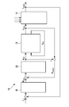
- the single figure of the drawing shows a schematic block diagram of an embodiment of a method according to the invention for controlling the temperature of a glow plug of an internal combustion engine.
- a control 10 is shown, which is composed of a temperature control 11, a resistance control 12, a glow plug 13 and a modeling 14 of the glow plug 13.
- the controller 10 is provided to control the temperature of the glow plug 13.
- the glow plug 13 is provided for operation in an internal combustion engine, in particular a self-igniting internal combustion engine.
- the glow plug 13 has an incandescent filament which is heated to a filament temperature Tglüh during operation. Furthermore, the Glow plug 13 according to the EP 315 034 B1 a surface that is heated in operation to a surface temperature.
- the glow plug 13 is acted upon by a voltage. This voltage is caused by a control voltage Ueff, which, as will be explained, is generated by the resistance control 12.
- Ueff a control voltage
- the voltage across the glow plug 13 causes a current to flow through the glow plug 13. This current is measured directly or indirectly and provided as measurement current Imess of modeling 14.
- the filament temperature Tglüh of the glow plug 13 is not measured or modeled.
- the measurement current Imess is supplied to the modeling 14.
- This modeling 14 is further acted upon by parameters of the glow plug 13 and / or other operating variables of the internal combustion engine. Depending on these input quantities, the modeling 14 determines a quantity which corresponds to the surface temperature of the glow plug 13 and which therefore continues to be used as the modeled surface temperature TModell.
- a setpoint temperature Tsoll is specified.
- This target temperature Tsoll refers to the surface of the glow plug 13.
- the target temperature Tsoll is compared with the modeled surface temperature TModell. The resulting difference acts on the temperature control 11th
- the temperature control 11 determines from the difference mentioned a set resistance Rsoll for the glow plug 13.
- the temperature control 11 are formed as a proportional, integral and / or differential controller.
- the temperature control 11 may include a characteristic map with the aid of which the setpoint resistance Rsoll is additionally influenced as a function of the rotational speed of the internal combustion engine and / or the load applied to the internal combustion engine.
- the determined by the temperature control 11 target resistance Rsoll can be limited to a lower and / or upper resistance, in particular to avoid overheating of the filament of the glow plug 13.
- the target resistance Rsoll is compared with a current resistance Ramid the glow plug 13.
- the determination of the current resistor Ramid will be described later. The difference between the two aforementioned resistors affects the resistance control 12.
- the resistance control 12 determines from the difference mentioned the already mentioned voltage Ueff, according to which, as already explained, the glow plug 13 is acted upon by a voltage.
- the resistance control 12 are designed as a proportional, integral and / or differential controller.
- the resistance control 12 may include a characteristic map with the aid of which the voltage Ueff is additionally influenced as a function of the rotational speed of the internal combustion engine and / or the load applied to the internal combustion engine.
- the determined by the resistance control 11 voltage Ueff can be limited to a lower and / or upper voltage value.
- the glow plug 13 acting on voltage Ueff is present.
- the current flowing through the glow plug 13 is present as measuring current Imess.
- the voltage Ueff is divided by the measuring current Imess. The result of this division represents the already mentioned actual resistance Ra Rail the glow plug 13.
- a desired setpoint temperature Tsoll for the glow plug 13 is predetermined.
- the modeled surface temperature TModell of the glow plug 13 is still low. The difference between the setpoint temperature Tsoll and the modeled surface temperature TModell is thus large, so that the temperature control 11 generates the setpoint resistance Rsoll in such a way that rapid heating of the glow plug 13 is achieved.
- the current through the glow plug 13 is substantially zero. This has a big current resistance.
- the current through the glow plug 13 causes the modeled surface temperature TModell to increase.
- the temperature controller 11 reduces the output-side target resistance Rsoll, so that the modeled surface temperature TModell approaches the desired target temperature Tsoll.
- the modeled surface temperature TModell substantially corresponds to the setpoint temperature Tsoll and the actual resistance Ra brochure substantially corresponds to the setpoint resistance Rsoll.
- the input side of the temperature control 11 and the resistance control 12 applied differences are thus substantially zero.
- the regulation 10 controls the surface temperature of the glow plug 13 to the predefinable setpoint temperature Tset.
- the thermal distance between the incandescent filament and the surface of the glow plug 13 is only slightly dependent on production- or aging-related parameter fluctuations. Furthermore, it is expedient if substantially only the filament has a temperature coefficient, the leads to the filament are substantially temperature-invariant, however.
- the modeling 14 of the glow plug 13 can be supplemented by an aging model.
- the glow phases of the glow plug 13 can be counted and, depending on this, the modeling 14 can be influenced.
- the controller 10 may, as explained, be aligned with a single glow plug. Alternatively, it is also possible that the controller 10 is provided for controlling the temperature of several glow plugs.
- the entire controller 10 may be formed as an analog circuit.
- a computer for example a microprocessor
- a storage medium for example a flash memory
- a computer program is stored, which is programmed so that when it runs on the computer, the method of the controller 10 is performed in a digital manner.
- the analog or digital control 10 may be a component of a control unit which is provided for controlling and / or regulating operating variables of the internal combustion engine.
Landscapes
- Engineering & Computer Science (AREA)
- Chemical & Material Sciences (AREA)
- Combustion & Propulsion (AREA)
- Mechanical Engineering (AREA)
- General Engineering & Computer Science (AREA)
- Combined Controls Of Internal Combustion Engines (AREA)
- Ignition Installations For Internal Combustion Engines (AREA)
Applications Claiming Priority (1)
| Application Number | Priority Date | Filing Date | Title |
|---|---|---|---|
| DE200610060632 DE102006060632A1 (de) | 2006-12-21 | 2006-12-21 | Verfahren zur Regelung der Temperatur einer Glühkerze einer Brennkraftmaschine |
Publications (2)
| Publication Number | Publication Date |
|---|---|
| EP1936183A2 true EP1936183A2 (fr) | 2008-06-25 |
| EP1936183A3 EP1936183A3 (fr) | 2015-03-04 |
Family
ID=39252571
Family Applications (1)
| Application Number | Title | Priority Date | Filing Date |
|---|---|---|---|
| EP07122064.4A Withdrawn EP1936183A3 (fr) | 2006-12-21 | 2007-12-03 | Procédé destiné à la régulation de la température d'une bougie de préchauffage d'un moteur à combustion interne |
Country Status (3)
| Country | Link |
|---|---|
| EP (1) | EP1936183A3 (fr) |
| JP (1) | JP5602341B2 (fr) |
| DE (1) | DE102006060632A1 (fr) |
Cited By (4)
| Publication number | Priority date | Publication date | Assignee | Title |
|---|---|---|---|---|
| EP2327872A3 (fr) * | 2009-11-28 | 2012-07-18 | BorgWarner BERU Systems GmbH | Procédé destiné au chauffage d'une bougie de préchauffage |
| WO2012113653A1 (fr) * | 2011-02-22 | 2012-08-30 | Robert Bosch Gmbh | Procédé et appareil de commande pour régler une température d'une bougie-crayon de préchauffage |
| EP2258939A3 (fr) * | 2009-06-04 | 2015-09-16 | BorgWarner Ludwigsburg GmbH | Procédé de réglage de la température d'une bougie de préchauffage |
| EP2711540A4 (fr) * | 2011-05-19 | 2015-12-30 | Bosch Corp | Procédé de commande d'attaque de bougie à incandescence et dispositif de commande d'attaque de bougie à incandescence |
Families Citing this family (9)
| Publication number | Priority date | Publication date | Assignee | Title |
|---|---|---|---|---|
| DE102008040971B4 (de) * | 2008-08-04 | 2012-12-27 | Robert Bosch Gmbh | Verfahren und Vorrichtung zum Regeln der Temperatur von Glühstiftkerzen in einer Brennkraftmaschine |
| DE102009047650B4 (de) | 2009-11-12 | 2022-10-06 | Robert Bosch Gmbh | Verfahren und Vorrichtung zur Bestimmung einer Temperatur einer Glühstiftkerze in einem Verbrennungsmotor |
| DE102010011044B4 (de) | 2010-03-11 | 2012-12-27 | Borgwarner Beru Systems Gmbh | Verfahren zum Regeln einer Glühkerze |
| JP2011256821A (ja) * | 2010-06-11 | 2011-12-22 | Ngk Spark Plug Co Ltd | グロープラグの通電制御装置 |
| DE102011085435A1 (de) * | 2011-10-28 | 2013-05-02 | Robert Bosch Gmbh | Verfahren und Vorrichtung zur Bestimmung einer Oberflächentemperatur einer Glühstiftkerze in einem Verbrennungsmotor |
| DE102012102013B3 (de) * | 2012-03-09 | 2013-06-13 | Borgwarner Beru Systems Gmbh | Verfahren zur Regelung der Temperatur einer Glühkerze |
| JP5971185B2 (ja) * | 2013-04-23 | 2016-08-17 | トヨタ自動車株式会社 | 発熱素子の表面温度制御方法 |
| DE102017109071B4 (de) | 2017-04-27 | 2022-10-20 | Borgwarner Ludwigsburg Gmbh | Verfahren zum Regeln der Temperatur von Glühkerzen |
| DE102017115917B4 (de) * | 2017-07-14 | 2022-02-10 | Borgwarner Ludwigsburg Gmbh | Verfahren zum Regeln der Oberflächentemperatur einer Glühkerze |
Family Cites Families (13)
| Publication number | Priority date | Publication date | Assignee | Title |
|---|---|---|---|---|
| US4726333A (en) * | 1986-11-28 | 1988-02-23 | Caterpillar Inc. | Glow plug alternator control |
| US4858576A (en) * | 1986-11-28 | 1989-08-22 | Caterpillar Inc. | Glow plug alternator control |
| DE3737745A1 (de) * | 1987-11-06 | 1989-05-18 | Bosch Gmbh Robert | Verfahren und vorrichtung zur regelung der temperatur insbesondere von gluehkerzen |
| JPH05157238A (ja) * | 1991-12-10 | 1993-06-22 | Matsushita Electric Ind Co Ltd | 点火装置 |
| JP3873307B2 (ja) * | 1995-09-20 | 2007-01-24 | 双葉電子工業株式会社 | 模型用グローエンジンの制御装置 |
| JPH1030491A (ja) * | 1996-07-11 | 1998-02-03 | Toyota Motor Corp | ディーゼルエンジンの燃焼異常判定装置 |
| US5724932A (en) * | 1996-10-18 | 1998-03-10 | Caterpillar Inc. | Alternating current control apparatus and method for glow plugs |
| JP2001336468A (ja) * | 2000-03-22 | 2001-12-07 | Ngk Spark Plug Co Ltd | グロープラグ制御装置、グロープラグ、及びエンジンの燃焼室内のイオン検出方法 |
| JP2003121285A (ja) * | 2001-10-19 | 2003-04-23 | Toyota Motor Corp | 圧力センサ |
| JP4047762B2 (ja) * | 2002-05-14 | 2008-02-13 | 日本特殊陶業株式会社 | グロープラグの制御装置 |
| DE10247042B3 (de) * | 2002-10-09 | 2004-05-06 | Beru Ag | Verfahren und Vorrichtung zum Steuern der Aufheizung der Glühkerzen eines Dieselmotors |
| JP3810744B2 (ja) * | 2003-01-29 | 2006-08-16 | 日本特殊陶業株式会社 | グロープラグ通電制御装置及びグロープラグ通電制御方法 |
| JP4723174B2 (ja) * | 2003-01-29 | 2011-07-13 | 日本特殊陶業株式会社 | グロープラグ通電制御装置及びグロープラグ通電制御方法 |
-
2006
- 2006-12-21 DE DE200610060632 patent/DE102006060632A1/de not_active Withdrawn
-
2007
- 2007-12-03 EP EP07122064.4A patent/EP1936183A3/fr not_active Withdrawn
- 2007-12-20 JP JP2007328489A patent/JP5602341B2/ja not_active Expired - Fee Related
Cited By (7)
| Publication number | Priority date | Publication date | Assignee | Title |
|---|---|---|---|---|
| EP2258939A3 (fr) * | 2009-06-04 | 2015-09-16 | BorgWarner Ludwigsburg GmbH | Procédé de réglage de la température d'une bougie de préchauffage |
| EP2327872A3 (fr) * | 2009-11-28 | 2012-07-18 | BorgWarner BERU Systems GmbH | Procédé destiné au chauffage d'une bougie de préchauffage |
| WO2012113653A1 (fr) * | 2011-02-22 | 2012-08-30 | Robert Bosch Gmbh | Procédé et appareil de commande pour régler une température d'une bougie-crayon de préchauffage |
| CN103380293A (zh) * | 2011-02-22 | 2013-10-30 | 罗伯特·博世有限公司 | 用于调节预热塞温度的方法和控制设备 |
| CN103380293B (zh) * | 2011-02-22 | 2016-08-17 | 罗伯特·博世有限公司 | 用于调节预热塞温度的方法和控制设备 |
| US10132288B2 (en) | 2011-02-22 | 2018-11-20 | Robert Bosch Gmbh | Method and control unit for setting a temperature of a glow plug |
| EP2711540A4 (fr) * | 2011-05-19 | 2015-12-30 | Bosch Corp | Procédé de commande d'attaque de bougie à incandescence et dispositif de commande d'attaque de bougie à incandescence |
Also Published As
| Publication number | Publication date |
|---|---|
| JP2008157614A (ja) | 2008-07-10 |
| JP5602341B2 (ja) | 2014-10-08 |
| EP1936183A3 (fr) | 2015-03-04 |
| DE102006060632A1 (de) | 2008-06-26 |
Similar Documents
| Publication | Publication Date | Title |
|---|---|---|
| DE19721176C2 (de) | System zur Überprüfung eines Drucksensors eines Kraftstoffversorgungssystems für eine Brennkraftmaschine insbesondere eines Kraftfahrzeugs | |
| DE10247042B3 (de) | Verfahren und Vorrichtung zum Steuern der Aufheizung der Glühkerzen eines Dieselmotors | |
| DE3638410C2 (fr) | ||
| DE102006060632A1 (de) | Verfahren zur Regelung der Temperatur einer Glühkerze einer Brennkraftmaschine | |
| DE19728814A1 (de) | Kühlanlage für einen Verbrennungsmotor eines Kraftfahrzeuges | |
| DE3237816A1 (de) | Verfahren und vorrichtung zur regelung der luftdurchsatzmenge in einer klimaanlage | |
| EP3045816B1 (fr) | Dispositif de commande d'une installation de brûleur | |
| EP0925434B1 (fr) | Systeme d'exploitation d'un moteur a combustion interne, en particulier d'un vehicule a moteur | |
| DE69124299T2 (de) | Verfahren und Vorrichtung zur Steuerung eines Magnetkraftschalters | |
| EP2678552B1 (fr) | Procédé et appareil de commande pour régler une température d'une bougie-crayon de préchauffage | |
| DE4134522A1 (de) | Einrichtung und verfahren zur elektronischen kraftstoffeinspritzsteuerung fuer verbrennungsmotor | |
| DE4433300C1 (de) | Verfahren und Vorrichtung zur Leerlaufeinstellung einer Brennkraftmaschine | |
| EP0445310A1 (fr) | Procédé et dispositif de régulation de la température "aller" d'un système de chauffage à plusieures chaudières | |
| DE102007035188B4 (de) | Verfahren zum Aufheizen eines Gassensors | |
| DE19707436C2 (de) | Steuergerät für Kraftfahrzeuge | |
| EP1923634A1 (fr) | Réglage du mélange air / gaz combustible sur la température de flamme ou de brûleur d'un appareil de chauffage | |
| DE19847457C2 (de) | Verfahren und Vorrichtung zur Steuerung einer Brennkraftmaschine | |
| DE4420122A1 (de) | Verfahren und Vorrichtung zur Bestimmung einer Endstellung einer Verstelleinrichtung in Fahrzeugen | |
| CH665705A5 (de) | Einrichtung zur beeinflussung eines regelgeraetes einer heizungsanlage von einem raumgeraet aus. | |
| DE102011084194A1 (de) | Verfahren und Recheneinheit zum Betrieb einer Zumesseinheit eines Common-Rail-Kraftstoffeinspritzsystems und Recheneinheit | |
| DE3737745A1 (de) | Verfahren und vorrichtung zur regelung der temperatur insbesondere von gluehkerzen | |
| DE4334720B4 (de) | Verfahren und Vorrichtung zur Steuerung einer Verstelleinrichtung bei Fahrzeugen | |
| WO2017148671A1 (fr) | Procédé et dispositif permettant de déterminer un instant d'injection pour l'injection d'un carburant | |
| DE10138819B4 (de) | Verfahren und System zum Regeln der Heizleistung eines Luftheizgerätes | |
| DE19748354B4 (de) | Verfahren und Vorrichtung zur Steuerung eines Stellelements |
Legal Events
| Date | Code | Title | Description |
|---|---|---|---|
| PUAI | Public reference made under article 153(3) epc to a published international application that has entered the european phase |
Free format text: ORIGINAL CODE: 0009012 |
|
| AK | Designated contracting states |
Kind code of ref document: A2 Designated state(s): AT BE BG CH CY CZ DE DK EE ES FI FR GB GR HU IE IS IT LI LT LU LV MC MT NL PL PT RO SE SI SK TR |
|
| AX | Request for extension of the european patent |
Extension state: AL BA HR MK RS |
|
| PUAL | Search report despatched |
Free format text: ORIGINAL CODE: 0009013 |
|
| AK | Designated contracting states |
Kind code of ref document: A3 Designated state(s): AT BE BG CH CY CZ DE DK EE ES FI FR GB GR HU IE IS IT LI LT LU LV MC MT NL PL PT RO SE SI SK TR |
|
| AX | Request for extension of the european patent |
Extension state: AL BA HR MK RS |
|
| RIC1 | Information provided on ipc code assigned before grant |
Ipc: F02D 41/14 20060101ALI20150126BHEP Ipc: F02P 19/02 20060101AFI20150126BHEP |
|
| AKY | No designation fees paid | ||
| AXX | Extension fees paid |
Extension state: RS Extension state: AL Extension state: MK Extension state: BA Extension state: HR |
|
| REG | Reference to a national code |
Ref country code: DE Ref legal event code: R108 |
|
| STAA | Information on the status of an ep patent application or granted ep patent |
Free format text: STATUS: THE APPLICATION IS DEEMED TO BE WITHDRAWN |
|
| 18D | Application deemed to be withdrawn |
Effective date: 20150905 |