EP1937178B1 - Systeme de planification, de simulation et de controle d'une trajectoire d'outil en 3d - Google Patents
Systeme de planification, de simulation et de controle d'une trajectoire d'outil en 3d Download PDFInfo
- Publication number
- EP1937178B1 EP1937178B1 EP06842407A EP06842407A EP1937178B1 EP 1937178 B1 EP1937178 B1 EP 1937178B1 EP 06842407 A EP06842407 A EP 06842407A EP 06842407 A EP06842407 A EP 06842407A EP 1937178 B1 EP1937178 B1 EP 1937178B1
- Authority
- EP
- European Patent Office
- Prior art keywords
- node
- physical
- cost
- goal
- path
- Prior art date
- Legal status (The legal status is an assumption and is not a legal conclusion. Google has not performed a legal analysis and makes no representation as to the accuracy of the status listed.)
- Ceased
Links
- 238000004088 simulation Methods 0.000 title description 4
- 238000000034 method Methods 0.000 claims abstract description 61
- 230000033001 locomotion Effects 0.000 claims abstract description 18
- 230000007704 transition Effects 0.000 claims description 22
- 230000006870 function Effects 0.000 claims description 9
- 238000004422 calculation algorithm Methods 0.000 claims description 8
- 238000004364 calculation method Methods 0.000 claims description 7
- 238000012545 processing Methods 0.000 claims description 5
- 230000009467 reduction Effects 0.000 claims description 5
- 210000004204 blood vessel Anatomy 0.000 claims description 4
- 230000008859 change Effects 0.000 claims description 4
- 238000013153 catheter ablation Methods 0.000 claims description 3
- 230000001131 transforming effect Effects 0.000 claims 5
- 230000001902 propagating effect Effects 0.000 claims 4
- 238000013507 mapping Methods 0.000 claims 3
- 230000000284 resting effect Effects 0.000 claims 2
- 238000002679 ablation Methods 0.000 abstract description 3
- 238000001356 surgical procedure Methods 0.000 abstract description 2
- 230000008569 process Effects 0.000 description 19
- 210000004072 lung Anatomy 0.000 description 9
- 230000009471 action Effects 0.000 description 8
- 206010028980 Neoplasm Diseases 0.000 description 6
- 238000001574 biopsy Methods 0.000 description 5
- 230000003902 lesion Effects 0.000 description 5
- 230000000747 cardiac effect Effects 0.000 description 4
- 210000001519 tissue Anatomy 0.000 description 4
- 238000002399 angioplasty Methods 0.000 description 3
- 238000013459 approach Methods 0.000 description 3
- 210000000621 bronchi Anatomy 0.000 description 3
- 210000005166 vasculature Anatomy 0.000 description 3
- 238000012937 correction Methods 0.000 description 2
- 238000001514 detection method Methods 0.000 description 2
- 238000005516 engineering process Methods 0.000 description 2
- 210000001105 femoral artery Anatomy 0.000 description 2
- 239000000835 fiber Substances 0.000 description 2
- 238000002594 fluoroscopy Methods 0.000 description 2
- 238000003780 insertion Methods 0.000 description 2
- 230000037431 insertion Effects 0.000 description 2
- 230000003993 interaction Effects 0.000 description 2
- 238000012986 modification Methods 0.000 description 2
- 230000004048 modification Effects 0.000 description 2
- 238000005457 optimization Methods 0.000 description 2
- 230000029058 respiratory gaseous exchange Effects 0.000 description 2
- 230000001953 sensory effect Effects 0.000 description 2
- 210000003437 trachea Anatomy 0.000 description 2
- 238000002604 ultrasonography Methods 0.000 description 2
- 210000001367 artery Anatomy 0.000 description 1
- 210000000988 bone and bone Anatomy 0.000 description 1
- 201000011510 cancer Diseases 0.000 description 1
- 230000001419 dependent effect Effects 0.000 description 1
- 238000013461 design Methods 0.000 description 1
- 238000003745 diagnosis Methods 0.000 description 1
- 238000002059 diagnostic imaging Methods 0.000 description 1
- 238000010586 diagram Methods 0.000 description 1
- 230000000694 effects Effects 0.000 description 1
- 238000002474 experimental method Methods 0.000 description 1
- 238000009472 formulation Methods 0.000 description 1
- 210000001035 gastrointestinal tract Anatomy 0.000 description 1
- 230000006872 improvement Effects 0.000 description 1
- 230000007246 mechanism Effects 0.000 description 1
- 239000000203 mixture Substances 0.000 description 1
- 230000000877 morphologic effect Effects 0.000 description 1
- 238000002428 photodynamic therapy Methods 0.000 description 1
- 238000007674 radiofrequency ablation Methods 0.000 description 1
- 238000009877 rendering Methods 0.000 description 1
- 230000033764 rhythmic process Effects 0.000 description 1
- 238000012360 testing method Methods 0.000 description 1
- 238000002560 therapeutic procedure Methods 0.000 description 1
- 238000012549 training Methods 0.000 description 1
- 230000009466 transformation Effects 0.000 description 1
- 238000000844 transformation Methods 0.000 description 1
- 238000013519 translation Methods 0.000 description 1
- 230000000007 visual effect Effects 0.000 description 1
- 238000011179 visual inspection Methods 0.000 description 1
- 210000000707 wrist Anatomy 0.000 description 1
Images




Classifications
-
- A—HUMAN NECESSITIES
- A61—MEDICAL OR VETERINARY SCIENCE; HYGIENE
- A61B—DIAGNOSIS; SURGERY; IDENTIFICATION
- A61B90/00—Instruments, implements or accessories specially adapted for surgery or diagnosis and not covered by any of the groups A61B1/00 - A61B50/00, e.g. for luxation treatment or for protecting wound edges
- A61B90/36—Image-producing devices or illumination devices not otherwise provided for
-
- A—HUMAN NECESSITIES
- A61—MEDICAL OR VETERINARY SCIENCE; HYGIENE
- A61B—DIAGNOSIS; SURGERY; IDENTIFICATION
- A61B90/00—Instruments, implements or accessories specially adapted for surgery or diagnosis and not covered by any of the groups A61B1/00 - A61B50/00, e.g. for luxation treatment or for protecting wound edges
- A61B90/10—Instruments, implements or accessories specially adapted for surgery or diagnosis and not covered by any of the groups A61B1/00 - A61B50/00, e.g. for luxation treatment or for protecting wound edges for stereotaxic surgery, e.g. frame-based stereotaxis
-
- A—HUMAN NECESSITIES
- A61—MEDICAL OR VETERINARY SCIENCE; HYGIENE
- A61B—DIAGNOSIS; SURGERY; IDENTIFICATION
- A61B17/00—Surgical instruments, devices or methods
- A61B17/00234—Surgical instruments, devices or methods for minimally invasive surgery
- A61B2017/00292—Surgical instruments, devices or methods for minimally invasive surgery mounted on or guided by flexible, e.g. catheter-like, means
- A61B2017/003—Steerable
- A61B2017/00318—Steering mechanisms
- A61B2017/00331—Steering mechanisms with preformed bends
-
- A—HUMAN NECESSITIES
- A61—MEDICAL OR VETERINARY SCIENCE; HYGIENE
- A61B—DIAGNOSIS; SURGERY; IDENTIFICATION
- A61B34/00—Computer-aided surgery; Manipulators or robots specially adapted for use in surgery
- A61B34/10—Computer-aided planning, simulation or modelling of surgical operations
- A61B2034/107—Visualisation of planned trajectories or target regions
-
- A—HUMAN NECESSITIES
- A61—MEDICAL OR VETERINARY SCIENCE; HYGIENE
- A61B—DIAGNOSIS; SURGERY; IDENTIFICATION
- A61B34/00—Computer-aided surgery; Manipulators or robots specially adapted for use in surgery
- A61B34/10—Computer-aided planning, simulation or modelling of surgical operations
Definitions
- the present invention relates to a system, apparatus and method for planning a tool path in a patient.
- Catheters are used to position other devices for balloon angioplasty, stenting, and tumor ablations.
- Today a catheter is maneuvered using visual feedback, often by 'live x-ray' also called fluoroscopy.
- Catheters come in many shapes and sizes with different flexibility. They are chosen for the procedure based on a surgeon's judgment, or sometimes based on statistical norms for the procedure.
- U.S. Patent No. 6,726,675 entitled “Remote control catheterization”, assigned to Navicath Corporation discloses a system that enables the automated control of catheters, which automatically feeds the catheter forward, as well as rotates it.
- catheter for the surgeon, but they may be selected based on statistical norms, rather than patient specific morphology. This non-optimal choice can slow the procedure or increase the risk to the patient.
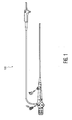
- a bronchoscope is used to examine deep areas of the lung, and an endoscope is used to enter natural body cavities such as either end of the GI tract or through small incisions such as in laparoscopic procedures.
- Colonoscopes and sigmoidoscopes are types of endoscopes.
- the scope is maneuvered for visual inspection, diagnosis, often through biopsy, as well as to deliver some forms of therapy such as Photodynamic therapy.
- a configuration space in the art in particular is considered to be the set of all poses representing the possible states of the tool.
- this is a 6 dimensional problem, including the 3D location and 3D orientation.
- 512x512x240 (X x Y x slices), or 62,914,560 locations.
- the angles can be coarsely discretized at each 10 degrees in rX, rY and rZ (also called roll, pitch, and yaw).
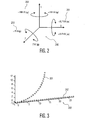
- the system, apparatus and method of the present invention reduce the configuration from 6 degrees of freedom to 3, by using the locations as states and storing the r (roll), p (pitch), w (yaw) angles that provide the orientation setting at the current state and by generating neighborhoods that are used to maintain kinematically correct angles of the catheter's and scope's tip from any orientation.
- This makes the calculation tractable in today's systems, and always faster in tomorrow's computing systems.
- the resulting path is kinematically correct (i.e. achievable with a given tool), collision-free and optimal in the discretized space.
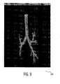
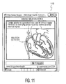
- a plan is generated for a bronchoscope to travel through the lungs to a target location such as for biopsy, and a plan for catheter motion is achieved through the blood vessels.
- Embodiments of the present invention are a non-obvious variation of the path planning technologies described in U.S. Patent Serial No. 6,604,005 to L.Dorst & K.Trovato and in "Method and apparatus for controlling maneuvers of a vehicle," U.S. Patent Serial No. 5,870,303 to K.Trovato and L.Dorst, February 9, 1999 .
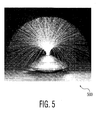
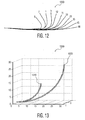
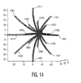
- a neighborhood contains all possible motions that a catheter can make. These are insertion (fwd motion), left and right turn (rotation), with costs weighted by the strain induced by following various turns and catheter rotation.
- step 790 the node is added to the heap. If it is already on the heap, then the value is updated and the heap adjusted.
- the new cost_to_goal is assigned to n, as is a new alpha, theta and phi.
- the values of alpha, theta and phi are calculated by adding the values of the nominal node's alpha, theta and phi to the parent's alpha, theta and phi.
- the revised 'best_parent' leading the best way to the 'seed' node, is assigned 'home'.
- the number of the thread is stored. This minimizes computation later on during path following, since the number of the thread maps directly to the control parameters, that is the amount that the scope is turned up/down and left/right.
- the neighborhood is defined more narrowly than theoretically possible. For example, the turning radius is enlarged beyond the smallest possible. This may compensate for unexpected control or sensing errors by a slight over correction during the procedure.
- the 'goal' node may be 'picked' by the physician, by showing the reachable states in 3 space.
- the physician can then pick a target location, such as the location of a constricted vessel proposed for a stent.
- a Computer Aided Detection system can highlight suspected lesions, and the physician can more easily pick from this subset of points.
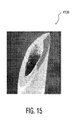
- a plan for the beveled needle is restricted to 2 dimensions, requiring that the needle be turned at 0 degrees or 180 degrees to remain within a single plane.
- the system, apparatus and method of the present invention enables planning in 3 dimensions, including orientation, without requiring a 6 dimensional configuration space.
- the present invention is used with a single arc neighborhood representing the curvature created by inserting a beveled needle into a body.
- a target is selected, along with a preferred orientation of entry.
- the planner uses the present invention to generate an optimal path from the entry area to the target ('goal'). There may be several equivalent ⁇ optimal' paths reachable from the surface, if a heuristic is not used to drive and shorten the search.
- the system can also be used as feedback for practicing a surgery. In a preferred embodiment, this is accomplished by rendering the likely image at the tip of the tool.
- the image may be the orthogonal image to the scope or catheter, or may be an image surrounding the scope or catheter.
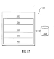
- the system 1600 includes an apparatus 1700, illustrated in FIG. 17 , for optimal path determination comprising a neighborhood generation module 730 to generate all reachable neighbors of a given pose, a transition cost t(n) calculation module 1603 to calculate the cost of transitioning to each neighbor from the given pose, a cost wave propagation module 770 to propagate cost waves from a goal to the given pose and a path determination module 700 that selects the lowest cost neighbor.
- a neighborhood generation module 730 to generate all reachable neighbors of a given pose
- a transition cost t(n) calculation module 1603 to calculate the cost of transitioning to each neighbor from the given pose
- a cost wave propagation module 770 to propagate cost waves from a goal to the given pose
- a path determination module 700 that selects the lowest cost neighbor.
Landscapes
- Health & Medical Sciences (AREA)
- Surgery (AREA)
- Life Sciences & Earth Sciences (AREA)
- Heart & Thoracic Surgery (AREA)
- Molecular Biology (AREA)
- Oral & Maxillofacial Surgery (AREA)
- Engineering & Computer Science (AREA)
- Biomedical Technology (AREA)
- Nuclear Medicine, Radiotherapy & Molecular Imaging (AREA)
- Medical Informatics (AREA)
- Pathology (AREA)
- Animal Behavior & Ethology (AREA)
- General Health & Medical Sciences (AREA)
- Public Health (AREA)
- Veterinary Medicine (AREA)
- Apparatus For Radiation Diagnosis (AREA)
- Instructional Devices (AREA)
- Endoscopes (AREA)
Claims (24)
- Système (1600) pour déterminer au moins un chemin pour un outil physique (1604) ayant un embout dirigeable (1605), comprenant :une mémoire (1608) pour stocker des informations de pose physique d'une pluralité de noeuds définis par une structure de données de noeuds, ladite pluralité de noeuds comprenant au moins un noeud de base qui correspond à un début physique souhaité ou à une pose d'objectif de l'embout dirigeable de l'outil physique lorsque l'embout dirigeable (1605) de l'outil physique est situé au noeud de base, dans lequel chaque noeud est situé à un emplacement discret différent dans un espace de tâche physique et dans lequel ladite structure de données de noeuds fournit pour chaque emplacement de noeud discret un stockage alloué pour stocker des informations d'orientation non discrète d'un chemin optimal passant par l'emplacement discret du noeud respectif dans l'espace de tâche physique, de sorte qu'une seule orientation de l'embout dirigeable (1605) de l'outil physique qui est optimale le long de tout chemin particulier entre un noeud de départ et le noeud de base agissant en tant que noeud d'objectif ou entre le noeud de base agissant en tant que noeud de départ et un noeud d'objectif est stockée à chaque état de configuration de position, ce qui engendre une réduction des exigences de stockage en vertu du mappage du problème non holonomique de direction de l'outil physique (1604) le long dudit chemin, ledit problème étant défini dans un espace de configuration 6D couvert par trois degrés de liberté de translation et par trois degrés de liberté de rotation caractérisant toutes les positions discrètes et toutes les orientations non discrètes pouvant être prises par l'embout dirigeable (1605), dans un espace de configuration 3D ;un module de génération de voisinage (730) pour générer et stocker dans la mémoire (1608) un voisinage d'un noeud d'espace de tâche physique comprenant au moins un noeud voisin de celui-ci, ledit noeud d'espace de tâche physique et ledit noeud voisin ayant au moins une direction de transition permissible entre eux ;un module de calcul de coût de transition (1603) pour calculer et stocker dans la mémoire (1608) le coût du noeud d'espace de tâche physique à l'au moins un noeud voisin généré le long de l'au moins une direction de transition permissible entre eux ;un module de propagation d'onde de coût (770) pour propager au moins une onde de coût calculée de l'au moins un noeud de base et pour assigner à chaque noeud d'espace de tâche physique et stocker dans la mémoire (1608) une valeur de coût et une direction de transition correspondant à un chemin de moindre coût physique d'une pose physique de l'embout dirigeable (1605) correspondant au noeud d'espace de tâche physique respectivement à la pose de départ physique ou à la pose d'objectif ; etun module de détermination de chemin (700) pour la détermination et l'identification dans la mémoire (1608) d'un chemin (1606) comprenant une séquence de noeuds d'espace de tâche physique le long du chemin de moindre coût physique commençant à une pose de départ comprenant un noeud d'espace de tâche physique correspondant à une pose naturelle physique/de repos de l'embout dirigeable (1605) de l'outil physique (1604) à un noeud de départ et suivant le chemin de moindre coût physique à partir de là dans la direction de transition permissible respectivement du noeud de départ à des noeuds qui le suivent jusqu'au noeud de base ou du noeud de base jusqu'à un noeud d'objectif
- Système (1600) selon la revendication 1, dans lequel l'embout dirigeable (1605) de l'outil physique (1604) est en outre configuré pour suivre le chemin déterminé stocké dans la mémoire (1608) par des transitions successives entre des noeuds d'espace de tâche physique de la séquence, en prenant la pose de chaque noeud d'espace de tâche physique dans la séquence de la pose de repos au noeud de départ à la pose d'objectif au noeud d'objectif
- Système (1600) selon la revendication 1, dans lequel le module de génération de voisinage (730) est en outre configuré pour que :l'au moins un noeud voisin comprend six dimensions y compris trois valeurs de position discrète et trois valeurs d'orientation non discrète, etl'au moins un noeud voisin est stocké dans la mémoire (1608) en tant que changement de chacune des trois valeurs de position discrète et des trois valeurs d'orientation non discrète d'un noeud au noeud voisin.
- Système (1600) selon la revendication 1, configuré en outre pour simuler la séquence de noeuds d'espace de tâche physique (1606) en tant que déplacement de l'outil le long du chemin physique stocké dans la mémoire (1608), dans lequel chaque noeud est une pose de l'embout dirigeable (1605) de l'outil (1604).
- Système (1600) selon la revendication 1, dans lequel le noeud de base est un noeud de départ.
- Système (1600) selon la revendication 1, dans lequel le noeud de départ est un noeud d'objectif.
- Système (1600) selon la revendication 1, dans lequel :l'outil (1604) est un cathéter (1000) ; etla séquence de noeuds d'espace de tâche physique (1606) correspond à une séquence d'emplacements de vaisseaux sanguins dérivés de la morphologie d'un patient.
- Système (1600) selon la revendication 1, dans lequel :l'outil (1604) est sélectionné dans le groupe se composant d'un endoscope, un bronchoscope (100), un cathéter (1001), un cathéter d'ablation cardiaque (1101), et une aiguille biseautée (1500) ; etla séquence de noeuds d'espace de tâche physique (1606) correspond à une séquence d'emplacements de passage dérivés de la morphologie d'un patient.
- Système (1600) selon la revendication 1, dans lequel le système comprend en outre un moyen pour transmettre la séquence (1606) à un intervenant (1602) qui utilise l'outil.
- Système (1600) selon la revendication 1, dans lequel le système comprend en outre un moyen pour transmettre la séquence (1606) à un contrôleur automatisé (1607) qui utilise automatiquement l'outil.
- Système (1600) selon la revendication 1, comprenant un appareil (1700) pour planifier un chemin de moindre coût physique pour un outil physique (1604) ayant un embout dirigeable (1605), comprenant :au moins un support de stockage lisible par ordinateur (1608) pour stocker des informations représentant une structure de données de noeuds définissant une pluralité de noeuds, chaque noeud étant situé à un emplacement discret différent dans un espace de tâche physique qui entoure un emplacement de l'embout dirigeable (1605) de l'outil physique (1604), dans lequel ladite structure de données de noeuds fournit pour chaque emplacement de noeud discret un stockage alloué pour stocker des informations d'orientation non discrète d'un chemin optimal passant par l'emplacement discret du noeud respectif dans l'espace de tâche physique, de sorte qu'une seule orientation de l'embout dirigeable (1605) de l'outil physique qui est optimale le long de tout chemin particulier entre un noeud de départ et un noeud de base agissant en tant que noeud d'objectif ou entre un noeud de base agissant en tant que noeud de départ et un noeud d'objectif est stockée à chaque état de configuration de position, ce qui engendre une réduction des exigences de stockage en vertu du mappage du problème non holonomique de direction de l'outil physique (1604) le long dudit chemin, ledit problème étant défini dans un espace de configuration 6D couvert par trois degrés de liberté de translation et par trois degrés de liberté de rotation caractérisant toutes les positions discrètes et toutes les orientations non discrètes pouvant être prises par l'embout dirigeable (1605), dans un espace de configuration 3D ;un moyen (1603, 770) pour assigner un coût à l'au moins une position voisine d'une position donnée de l'embout dirigeable (1605) dans l'espace de tâche physique, sur la base d'une mesure (1603) qui varie en fonction de la position dans la représentation de structure de données de noeuds rendue discrète, le coût correspondant à au moins un aspect physique de l'espace de tâche physique afin d'établir un coût de l'au moins une position voisine à la position donnée ;un moyen pour démarrer le moyen d'assignation à une position de départ ;un moyen (700) pour provoquer l'itération du moyen d'assignation afin d'assigner des coûts respectifs à toutes les positions atteignables dans la représentation rendue discrète en ondes se propageant vers une position de départ à partir d'une position d'objectif; etun moyen (770) pour identifier un chemin de moindre coût entre la position de départ et la position d'objectif dans la représentation rendue discrète sur la base des coûts assignés.
- Procédé (700) pour déterminer au moins une spécification de déplacement physique pour un outil physique (1604) ayant un embout dirigeable (1605), comprenant les étapes de :l'exécution des étapes suivantes dans au moins une unité de traitement de données numériques (1601) et au moins un support de stockage lisible par ordinateur (1608) qui est inclus dans ou couplé à l'au moins une unité de traitement de données numériques (1601) ;la représentation, dans l'au moins un support de stockage lisible par ordinateur, d'une structure de données de noeuds définissant une pluralité de noeuds, chacun d'eux étant situé à un emplacement discret différent dans un espace de tâche physique qui entoure l'embout dirigeable (1605) dans la réalité physique, dans lequel pour chaque emplacement de noeud discret des informations d'orientation non discrètes d'un chemin optimal passant par l'emplacement discret du noeud respectif dans l'espace de tâche physique sont définies par ladite structure de données de noeuds, de sorte qu'une seule orientation de l'embout dirigeable (1605) de l'outil physique qui est optimale le long de tout chemin particulier entre un noeud de départ et un noeud de base agissant en tant que noeud d'objectif ou entre un noeud de base agissant en tant que noeud de départ et un noeud d'objectif est stockée à chaque état de configuration de position, ce qui engendre une réduction des exigences de stockage en vertu du mappage du problème non holonomique de direction de l'outil physique (1604) le long dudit chemin, ledit problème étant défini dans un espace de configuration 6D couvert par trois degrés de liberté de translation et par trois degrés de liberté de rotation caractérisant toutes les positions discrètes et toutes les orientations non discrètes pouvant être prises par l'embout dirigeable (1605), dans un espace de configuration 3D ; etla propagation d'ondes de coût (770), dans la structure de données de noeuds, pour remplir une partie de la structure de données de noeuds entre le noeud de départ et le noeud d'objectif avec des valeurs de coût en fonction d'une métrique variant dans l'espace, les valeurs de coût représentant des aspects physiques de l'espace de tâche physique par rapport au déplacement physique de l'embout dirigeable (1605).
- Procédé (700) selon la revendication 12, dans lequel l'étape de propagation d'ondes (770) comprend en outre l'étape de guidage par une heuristique.
- Procédé (700) selon la revendication 12, comprend en outre les étapes de :la dérivation (701) d'une séquence de représentations de poses d'embout dirigeable dans la structure de données de noeuds (1608), en utilisant les valeurs de coût, lesquelles représentations représentent des poses physiques définissant un chemin de moindre coût (1606) d'une pose de départ à une pose d'objectif dans l'espace de tâche physique ; etla fourniture de la séquence (1606) sous une forme électronique utilisable par l'outil (1604) pour suivre le chemin (1606).
- Procédé (700) selon la revendication 12, dans lequel l'étape de
la propagation d'ondes de coût (770) dans la structure de données de noeuds comprend les étapes de :a) la détermination d'un objectif de coût pour chaque voisin d'un noeud d'origine dans la structure de données de noeuds (1608) ; etb) lorsqu'une valeur d'objectif de coût améliorée est déterminée pour un voisin, l'exécution des étapes de :i. l'assignation (1603) de l'objectif de coût déterminé amélioré au voisin du noeud d'origine, lequel objectif de coût détermine des aspects physiques de l'espace de tâche physique et le déplacement physique de l'embout dirigeable (1605) et l'objectif de coût ; etii. la mise à jour des voisins (770) avec l'objectif de coût déterminé amélioré et un pointeur vers le noeud d'origine en tant que meilleur parent dans la structure de données de noeuds (1608). - Procédé (700) selon la revendication 15, comprenant en outre les étapes de :la dérivation d'une séquence (1606) de représentations de poses d'embout dirigeable dans la structure de données de noeuds, en utilisant les valeurs de coût, lesquelles représentations représentent des poses physiques définissant un chemin de moindre coût (1606) d'une pose de départ à une pose d'objectif dans l'espace de tâche physique ; etla fourniture de la séquence (1606) sous une forme électronique utilisable par un contrôleur (1602, 1607) de l'embout dirigeable (1001) pour suivre le chemin (1606).
- Procédé (700) selon la revendication 15, comprenant en outre les étapes de :la première transformation de la pose d'objectif physique en informations d'au moins un état d'objectif dans la structure de données de noeuds ;la deuxième transformation d'une pose de départ physique en informations d'un état de départ ; en assignant des coûts à des états dans la structure de données de noeuds afin que, à chaque état atteignable respectif, il soit assigné une valeur de coût représentant le coût d'un chemin optimal de l'état de départ à l'état d'obj ectif ; etle suivi de l'état de départ à l'état d'objectif pour obtenir une séquence (1606) de représentations de pose d'objet dans la structure de données de noeuds, lesquelles représentations représentent des poses physiques définissant un chemin de moindre coût (1606) de la pose de départ à la pose d'objectif dans l'espace de tâche physique.
- Procédé (700) selon la revendication 17, comprenant en outre les étapes de :la détermination, après l'étape de la deuxième transformation, si le chemin existe en utilisant un algorithme prédéterminé ; etl'arrêt du procédé après l'étape de détermination, lorsqu'il est déterminé qu'il n'existe pas de chemin.
- Procédé (700) selon la revendication 17, dans lequel l'étape d'assignation comprend en outre l'évaluation du coût d'après une fonction de métrique variant dans l'espace.
- Procédé (700) selon la revendication 17, dans lequel l'étape d'assignation comprend en outre l'étape de mesure (1603) de valeurs de coûts de transitions entre des états voisins avec une métrique.
- Procédé (700) selon la revendication 20, dans lequel l'étape d'assignation comprend en outre l'étape de minimisation d'une fonction de tension et de contrainte sur l'embout dirigeable (1605) dans l'espace de tâche en augmentant le coût d'après une fonction de coût prédéterminée de tension et de contrainte sur l'embout dirigeable (1605).
- Procédé (700) selon la revendication 17, dans lequel l'étape d'assignation comprend en outre l'étape d'évaluation de coût d'après une fonction de métrique variant dans l'espace, dans lequel des points contraints dans l'espace de tâche physique sont exprimés comme nécessitant des transitions de coûts supérieurs dans la structure de données de noeuds.
- Procédé (700) selon la revendication 17, comprenant en outre l'étape de :la troisième transformation d'au moins un obstacle physique dans l'espace de tâche physique en au moins un noeud d'obstacle dans la structure de données de noeuds ; etdans lequel, l'étape d'assignation comprend en outre l'étape d'assignation de coût afin que chaque chemin optimal évite l'au moins un noeud d'obstacle de sorte que l'étape de suivi engendre un chemin évitant l'obstacle.
- Procédé (700) selon la revendication 23, dans lequel l'étape de la troisième transformation comprend en outre l'assignation d'une valeur sensiblement infinie de coût à l'au moins un noeud d'obstacle, de telle manière que l'au moins un noeud d'obstacle fasse partie d'une fonction de métrique variant dans l'espace qui mesure le coût.
Applications Claiming Priority (2)
| Application Number | Priority Date | Filing Date | Title |
|---|---|---|---|
| US72518505P | 2005-10-11 | 2005-10-11 | |
| PCT/IB2006/053672 WO2007042986A2 (fr) | 2005-10-11 | 2006-10-06 | Systeme de planification, de simulation et de controle d'une trajectoire d'outil en 3d |
Publications (2)
| Publication Number | Publication Date |
|---|---|
| EP1937178A2 EP1937178A2 (fr) | 2008-07-02 |
| EP1937178B1 true EP1937178B1 (fr) | 2011-12-14 |
Family
ID=37943195
Family Applications (1)
| Application Number | Title | Priority Date | Filing Date |
|---|---|---|---|
| EP06842407A Ceased EP1937178B1 (fr) | 2005-10-11 | 2006-10-06 | Systeme de planification, de simulation et de controle d'une trajectoire d'outil en 3d |
Country Status (6)
| Country | Link |
|---|---|
| US (1) | US8417491B2 (fr) |
| EP (1) | EP1937178B1 (fr) |
| JP (1) | JP5442993B2 (fr) |
| CN (1) | CN101282693B (fr) |
| AT (1) | ATE536829T1 (fr) |
| WO (1) | WO2007042986A2 (fr) |
Cited By (1)
| Publication number | Priority date | Publication date | Assignee | Title |
|---|---|---|---|---|
| US9700292B2 (en) | 2012-09-17 | 2017-07-11 | DePuy Synthes Products, Inc. | Systems and methods for surgical and interventional planning, support, post-operative follow-up, and functional recovery tracking |
Families Citing this family (91)
| Publication number | Priority date | Publication date | Assignee | Title |
|---|---|---|---|---|
| US9867530B2 (en) | 2006-08-14 | 2018-01-16 | Volcano Corporation | Telescopic side port catheter device with imaging system and method for accessing side branch occlusions |
| US9037215B2 (en) * | 2007-01-31 | 2015-05-19 | The Penn State Research Foundation | Methods and apparatus for 3D route planning through hollow organs |
| US10219780B2 (en) | 2007-07-12 | 2019-03-05 | Volcano Corporation | OCT-IVUS catheter for concurrent luminal imaging |
| US9596993B2 (en) | 2007-07-12 | 2017-03-21 | Volcano Corporation | Automatic calibration systems and methods of use |
| EP2178442B1 (fr) | 2007-07-12 | 2017-09-06 | Volcano Corporation | Cathéter pour imagerie in-vivo |
| WO2009146176A1 (fr) * | 2008-04-14 | 2009-12-03 | Blake Larson | Dispositif et méthode de chirurgie du mammaire guidée par irm |
| JP2011525984A (ja) * | 2008-06-26 | 2011-09-29 | コーニンクレッカ フィリップス エレクトロニクス エヌ ヴィ | 高速且つ正確な経路プランニングのための方法及びシステム |
| RU2011120186A (ru) | 2008-10-20 | 2012-11-27 | Конинклейке Филипс Электроникс, Н.В. | Способ и система локализации на основе изображений |
| US8568302B2 (en) * | 2008-11-11 | 2013-10-29 | Intuitive Surgical Operations, Inc. | Method and system for steerable medical device path definition and following during insertion and retraction |
| US20100121148A1 (en) | 2008-11-11 | 2010-05-13 | Intuitive Surgical, Inc. | Method and system for steerable medical device path definition and following during insertion and retraction |
| US9055865B2 (en) | 2008-11-11 | 2015-06-16 | Intuitive Surgical Operations, Inc. | Method and system for measuring inserted length of a medical device using internal referenced sensors |
| EP2381868A1 (fr) * | 2008-12-29 | 2011-11-02 | Koninklijke Philips Electronics B.V. | Planification des interactions de courbure, multiples rayons de courbure et voisinages adaptatifs |
| RU2596882C2 (ru) * | 2008-12-29 | 2016-09-10 | Конинклейке Филипс Электроникс Н.В. | Планирование траектории для уменьшения повреждения тканей в процессе минимально инвазивной хирургии |
| CN102264313A (zh) * | 2008-12-29 | 2011-11-30 | 皇家飞利浦电子股份有限公司 | 补偿同轴插管的规划和装配 |
| WO2010125481A1 (fr) | 2009-04-29 | 2010-11-04 | Koninklijke Philips Electronics, N.V. | Estimation de la profondeur en temps réel à partir d'images endoscopiques monoculaires |
| IT1395018B1 (it) | 2009-07-22 | 2012-09-05 | Surgica Robotica S R L | Apparecchiatura per procedure chirurgiche minimamente invasive |
| CA2807614C (fr) * | 2009-08-18 | 2018-10-30 | Airway Limited | Simulateur d'endoscope |
| FR2959409B1 (fr) | 2010-05-03 | 2012-06-29 | Gen Electric | Procede de determination d'un trajet d'insertion d'un outil dans une matricee tissulaire pouvant se deformer et systeme robotise mettant en oeuvre le procede |
| CN103209653B (zh) * | 2010-11-18 | 2017-04-26 | 皇家飞利浦电子股份有限公司 | 用于概率消融规划的系统 |
| US11141063B2 (en) | 2010-12-23 | 2021-10-12 | Philips Image Guided Therapy Corporation | Integrated system architectures and methods of use |
| US11040140B2 (en) | 2010-12-31 | 2021-06-22 | Philips Image Guided Therapy Corporation | Deep vein thrombosis therapeutic methods |
| WO2012106310A1 (fr) * | 2011-02-04 | 2012-08-09 | The Penn State Research Foundation | Procédé et dispositif pour déterminer l'emplacement d'un endoscope |
| EP2731532B1 (fr) * | 2011-07-11 | 2019-03-27 | Koninklijke Philips N.V. | Appareil de planification d'application d'énergie |
| WO2013033592A1 (fr) | 2011-08-31 | 2013-03-07 | Volcano Corporation | Joint rotatif électro-optique et procédés d'utilisation |
| TWI463964B (zh) * | 2012-03-03 | 2014-12-11 | Univ China Medical | 手術影像導引定位裝置及其系統 |
| ES2387785B1 (es) * | 2012-05-14 | 2013-05-08 | Universitat Politècnica De Catalunya | Procedimiento y sistema de generación de un recorrido para una broncoscopia virtual |
| RU2666580C2 (ru) | 2012-10-02 | 2018-09-11 | Конинклейке Филипс Н.В. | Отображение объема с использованием оптических датчиков формы |
| US9292918B2 (en) | 2012-10-05 | 2016-03-22 | Volcano Corporation | Methods and systems for transforming luminal images |
| US10568586B2 (en) | 2012-10-05 | 2020-02-25 | Volcano Corporation | Systems for indicating parameters in an imaging data set and methods of use |
| US20140100454A1 (en) | 2012-10-05 | 2014-04-10 | Volcano Corporation | Methods and systems for establishing parameters for three-dimensional imaging |
| CA2887421A1 (fr) | 2012-10-05 | 2014-04-10 | David Welford | Systemes et procedes pour amplifier la lumiere |
| US9324141B2 (en) | 2012-10-05 | 2016-04-26 | Volcano Corporation | Removal of A-scan streaking artifact |
| US9367965B2 (en) | 2012-10-05 | 2016-06-14 | Volcano Corporation | Systems and methods for generating images of tissue |
| US9286673B2 (en) | 2012-10-05 | 2016-03-15 | Volcano Corporation | Systems for correcting distortions in a medical image and methods of use thereof |
| US10070827B2 (en) | 2012-10-05 | 2018-09-11 | Volcano Corporation | Automatic image playback |
| US11272845B2 (en) | 2012-10-05 | 2022-03-15 | Philips Image Guided Therapy Corporation | System and method for instant and automatic border detection |
| US9858668B2 (en) | 2012-10-05 | 2018-01-02 | Volcano Corporation | Guidewire artifact removal in images |
| US9307926B2 (en) | 2012-10-05 | 2016-04-12 | Volcano Corporation | Automatic stent detection |
| US9840734B2 (en) | 2012-10-22 | 2017-12-12 | Raindance Technologies, Inc. | Methods for analyzing DNA |
| JP6322210B2 (ja) | 2012-12-13 | 2018-05-09 | ボルケーノ コーポレイション | 標的化された挿管のためのデバイス、システム、および方法 |
| US9709379B2 (en) | 2012-12-20 | 2017-07-18 | Volcano Corporation | Optical coherence tomography system that is reconfigurable between different imaging modes |
| US11406498B2 (en) | 2012-12-20 | 2022-08-09 | Philips Image Guided Therapy Corporation | Implant delivery system and implants |
| US10939826B2 (en) | 2012-12-20 | 2021-03-09 | Philips Image Guided Therapy Corporation | Aspirating and removing biological material |
| US10942022B2 (en) | 2012-12-20 | 2021-03-09 | Philips Image Guided Therapy Corporation | Manual calibration of imaging system |
| WO2014113188A2 (fr) | 2012-12-20 | 2014-07-24 | Jeremy Stigall | Localisation d'images intravasculaires |
| US10595820B2 (en) | 2012-12-20 | 2020-03-24 | Philips Image Guided Therapy Corporation | Smooth transition catheters |
| US10058284B2 (en) | 2012-12-21 | 2018-08-28 | Volcano Corporation | Simultaneous imaging, monitoring, and therapy |
| CA2896004A1 (fr) | 2012-12-21 | 2014-06-26 | Nathaniel J. Kemp | Mise en tampon optique efficace en energie utilisant un commutateur optique |
| EP2936626A4 (fr) | 2012-12-21 | 2016-08-17 | David Welford | Systèmes et procédés permettant de réduire une émission de longueur d'onde de lumière |
| WO2014100530A1 (fr) * | 2012-12-21 | 2014-06-26 | Whiseant Chester | Système et procédé pour l'orientation et le fonctionnement de cathéter |
| JP2016502884A (ja) | 2012-12-21 | 2016-02-01 | ダグラス メイヤー, | 延在カテーテル本体テレスコープを有する回転可能超音波撮像カテーテル |
| EP2934280B1 (fr) | 2012-12-21 | 2022-10-19 | Mai, Jerome | Imagerie à ultrasons pourvue d'une densité de ligne variable |
| WO2014099672A1 (fr) | 2012-12-21 | 2014-06-26 | Andrew Hancock | Système et procédé pour le traitement multivoie de signaux d'image |
| US9612105B2 (en) | 2012-12-21 | 2017-04-04 | Volcano Corporation | Polarization sensitive optical coherence tomography system |
| US9486143B2 (en) | 2012-12-21 | 2016-11-08 | Volcano Corporation | Intravascular forward imaging device |
| EP2936426B1 (fr) | 2012-12-21 | 2021-10-13 | Jason Spencer | Système et procédé de traitement graphique de données médicales |
| JP6030435B2 (ja) | 2012-12-25 | 2016-11-24 | 富士フイルム株式会社 | 画像処理装置および画像処理方法、並びに画像処理プログラム |
| US10226597B2 (en) | 2013-03-07 | 2019-03-12 | Volcano Corporation | Guidewire with centering mechanism |
| WO2014138555A1 (fr) | 2013-03-07 | 2014-09-12 | Bernhard Sturm | Segmentation multimodale dans des images intravasculaires |
| US10638939B2 (en) | 2013-03-12 | 2020-05-05 | Philips Image Guided Therapy Corporation | Systems and methods for diagnosing coronary microvascular disease |
| US20140276923A1 (en) | 2013-03-12 | 2014-09-18 | Volcano Corporation | Vibrating catheter and methods of use |
| US11026591B2 (en) | 2013-03-13 | 2021-06-08 | Philips Image Guided Therapy Corporation | Intravascular pressure sensor calibration |
| JP6339170B2 (ja) | 2013-03-13 | 2018-06-06 | ジンヒョン パーク | 回転式血管内超音波装置から画像を生成するためのシステム及び方法 |
| US9301687B2 (en) | 2013-03-13 | 2016-04-05 | Volcano Corporation | System and method for OCT depth calibration |
| US12343198B2 (en) | 2013-03-14 | 2025-07-01 | Philips Image Guided Therapy Corporation | Delivery catheter having imaging capabilities |
| US10292677B2 (en) | 2013-03-14 | 2019-05-21 | Volcano Corporation | Endoluminal filter having enhanced echogenic properties |
| US20160030151A1 (en) | 2013-03-14 | 2016-02-04 | Volcano Corporation | Filters with echogenic characteristics |
| US10219887B2 (en) | 2013-03-14 | 2019-03-05 | Volcano Corporation | Filters with echogenic characteristics |
| US10449002B2 (en) * | 2013-09-20 | 2019-10-22 | Innovative Surgical Solutions, Llc | Method of mapping a nerve |
| US10376208B2 (en) * | 2013-09-20 | 2019-08-13 | Innovative Surgical Solutions, Llc | Nerve mapping system |
| US10376209B2 (en) * | 2013-09-20 | 2019-08-13 | Innovative Surgical Solutions, Llc | Neural locating method |
| CN106062822B (zh) | 2014-03-04 | 2020-11-03 | 赞克特机器人有限公司 | 用于针插入的动态规划方法 |
| CN106659374B (zh) | 2014-07-02 | 2021-04-02 | 柯惠有限合伙公司 | 在3d导航时提供距离和取向反馈的系统和方法 |
| JP6521707B2 (ja) | 2014-07-10 | 2019-05-29 | キヤノン株式会社 | 穿刺プランニング装置及び穿刺システム |
| JP6356623B2 (ja) | 2015-03-18 | 2018-07-11 | 富士フイルム株式会社 | 画像処理装置、方法、及びプログラム |
| US10278616B2 (en) | 2015-05-12 | 2019-05-07 | Navix International Limited | Systems and methods for tracking an intrabody catheter |
| US10188465B2 (en) * | 2015-08-26 | 2019-01-29 | Biosense Webster (Israel) Ltd. | Automatic ENT surgery preplanning using a backtracking maze problem solution |
| CN105559887B (zh) * | 2015-12-11 | 2018-01-30 | 哈尔滨工业大学 | 用于手术机器人的基于力反馈的手术切割训练系统及方法 |
| EP3416581B1 (fr) * | 2016-02-16 | 2024-01-03 | Mentice AB | Systèmes d'acheminement d'un cathéter dans un vaisseau |
| WO2018011757A1 (fr) * | 2016-07-14 | 2018-01-18 | Navix International Limited | Navigation par cathéter à suivi caractéristique |
| US10631933B2 (en) | 2016-08-31 | 2020-04-28 | Covidien Lp | Pathway planning for use with a navigation planning and procedure system |
| US10321833B2 (en) | 2016-10-05 | 2019-06-18 | Innovative Surgical Solutions. | Neural locating method |
| CN106856067B (zh) * | 2017-01-18 | 2019-04-02 | 北京大学人民医院 | 一种智能化电子模拟纤维支气管镜训练装置 |
| JP7144408B2 (ja) * | 2017-06-02 | 2022-09-29 | テルモ株式会社 | 経路選択支援システム、経路選択支援プログラムを記録した記録媒体、および経路選択支援方法 |
| JP7214631B2 (ja) * | 2017-06-02 | 2023-01-30 | テルモ株式会社 | 経路選択支援システム、および経路選択支援プログラムを記録した記録媒体 |
| US11317972B2 (en) | 2018-03-17 | 2022-05-03 | Canon U.S.A., Inc. | Method for virtual device positioning on skin surface in 3D medical image data |
| JP7384160B2 (ja) * | 2018-07-26 | 2023-11-21 | ソニーグループ株式会社 | 情報処理装置、情報処理方法及びプログラム |
| US12082883B2 (en) | 2020-01-09 | 2024-09-10 | Canon U.S.A., Inc. | Enhanced planning and visualization with curved instrument pathway and its curved instrument |
| CN113282077B (zh) * | 2021-04-08 | 2022-06-17 | 浙江工业大学 | 基于正态分布和雅可比矩阵的同心管机器人运动规划方法 |
| CN116421311B (zh) * | 2023-04-14 | 2026-06-26 | 合肥工业大学 | 基于术前术中三维网格融合的术中危险区域生成系统 |
| CN121059279B (zh) * | 2025-08-25 | 2026-05-01 | 广东工业大学 | 一种融合改进a算法与人工势场法的柔性针穿刺路径规划方法 |
Family Cites Families (11)
| Publication number | Priority date | Publication date | Assignee | Title |
|---|---|---|---|---|
| US5870303A (en) * | 1987-11-20 | 1999-02-09 | Philips Electronics North America Corporation | Method and apparatus for controlling maneuvers of a vehicle |
| EP0317020B1 (fr) * | 1987-11-20 | 1995-04-19 | Koninklijke Philips Electronics N.V. | Méthode et dispositif pour l'établissement de route |
| US6015414A (en) * | 1997-08-29 | 2000-01-18 | Stereotaxis, Inc. | Method and apparatus for magnetically controlling motion direction of a mechanically pushed catheter |
| JP4053117B2 (ja) | 1997-10-17 | 2008-02-27 | 東芝医用システムエンジニアリング株式会社 | 画像処理装置 |
| IL123646A (en) * | 1998-03-11 | 2010-05-31 | Refael Beyar | Remote control catheterization |
| US7778688B2 (en) * | 1999-05-18 | 2010-08-17 | MediGuide, Ltd. | System and method for delivering a stent to a selected position within a lumen |
| US6695774B2 (en) * | 2001-01-19 | 2004-02-24 | Endactive, Inc. | Apparatus and method for controlling endoscopic instruments |
| EP1499235B1 (fr) * | 2002-04-17 | 2016-08-17 | Covidien LP | Structures et techniques associees a un endoscope permettant de naviguer jusqu'a une cible dans une structure ramifiee |
| US7822461B2 (en) * | 2003-07-11 | 2010-10-26 | Siemens Medical Solutions Usa, Inc. | System and method for endoscopic path planning |
| US7280863B2 (en) * | 2003-10-20 | 2007-10-09 | Magnetecs, Inc. | System and method for radar-assisted catheter guidance and control |
| JP4323288B2 (ja) * | 2003-10-31 | 2009-09-02 | オリンパス株式会社 | 挿入支援システム |
-
2006
- 2006-10-06 EP EP06842407A patent/EP1937178B1/fr not_active Ceased
- 2006-10-06 JP JP2008535158A patent/JP5442993B2/ja not_active Expired - Fee Related
- 2006-10-06 AT AT06842407T patent/ATE536829T1/de active
- 2006-10-06 WO PCT/IB2006/053672 patent/WO2007042986A2/fr not_active Ceased
- 2006-10-06 CN CN2006800377092A patent/CN101282693B/zh not_active Expired - Fee Related
- 2006-10-06 US US12/088,870 patent/US8417491B2/en not_active Expired - Fee Related
Cited By (6)
| Publication number | Priority date | Publication date | Assignee | Title |
|---|---|---|---|---|
| US9700292B2 (en) | 2012-09-17 | 2017-07-11 | DePuy Synthes Products, Inc. | Systems and methods for surgical and interventional planning, support, post-operative follow-up, and functional recovery tracking |
| US10166019B2 (en) | 2012-09-17 | 2019-01-01 | DePuy Synthes Products, Inc. | Systems and methods for surgical and interventional planning, support, post-operative follow-up, and, functional recovery tracking |
| US10595844B2 (en) | 2012-09-17 | 2020-03-24 | DePuy Synthes Products, Inc. | Systems and methods for surgical and interventional planning, support, post-operative follow-up, and functional recovery tracking |
| US11749396B2 (en) | 2012-09-17 | 2023-09-05 | DePuy Synthes Products, Inc. | Systems and methods for surgical and interventional planning, support, post-operative follow-up, and, functional recovery tracking |
| US11798676B2 (en) | 2012-09-17 | 2023-10-24 | DePuy Synthes Products, Inc. | Systems and methods for surgical and interventional planning, support, post-operative follow-up, and functional recovery tracking |
| US11923068B2 (en) | 2012-09-17 | 2024-03-05 | DePuy Synthes Products, Inc. | Systems and methods for surgical and interventional planning, support, post-operative follow-up, and functional recovery tracking |
Also Published As
| Publication number | Publication date |
|---|---|
| JP2009511155A (ja) | 2009-03-19 |
| CN101282693A (zh) | 2008-10-08 |
| CN101282693B (zh) | 2011-07-06 |
| WO2007042986A3 (fr) | 2007-10-11 |
| WO2007042986A2 (fr) | 2007-04-19 |
| ATE536829T1 (de) | 2011-12-15 |
| EP1937178A2 (fr) | 2008-07-02 |
| US8417491B2 (en) | 2013-04-09 |
| US20080234700A1 (en) | 2008-09-25 |
| JP5442993B2 (ja) | 2014-03-19 |
Similar Documents
| Publication | Publication Date | Title |
|---|---|---|
| US8417491B2 (en) | 3D tool path planning, simulation and control system | |
| JP7816722B2 (ja) | センサベースのナビゲーションと内視鏡検査との組み合わせを用いた外科用システム | |
| US12364552B2 (en) | Path-based navigation of tubular networks | |
| CN105979899B (zh) | 用于设备感知柔性工具配准的系统和方法 | |
| JP2020526254A (ja) | 器具挿入補償 | |
| CN107072717A (zh) | 用于自适应输入映射的系统和方法 | |
| JP2022546421A (ja) | 位置センサの重みベースの位置合わせのためのシステム及び方法 | |
| KR20230027240A (ko) | 의료 기구를 위한 제어 스킴 교정 | |
| US10959785B2 (en) | Tissue shaving instrument with navigation sensor | |
| US20240366247A1 (en) | Hollow tube surgical instrument with single axis sensor | |
| US20110295199A1 (en) | Planning and assembly of compensating concentric cannulas | |
| Wu et al. | Motion planning of continuum tubular robots based on centerlines extracted from statistical atlas | |
| WO2023150162A1 (fr) | Système de cathéter robotique et procédés d'affichage d'actions correctives pour celui-ci | |
| CN116829089A (zh) | 用于基于术中成像更新图形用户界面的系统 | |
| JP2026502809A (ja) | ガイド付きツール交換の復元性のためのシステム及び方法 | |
| US20110270040A1 (en) | Planning for curvature interactions, multiple radii of curvature and adaptive neighborhoods | |
| CN115005979B (zh) | 计算机可读存储介质、电子设备及手术机器人系统 | |
| US20240252260A1 (en) | Method, equipment and storage medium for navigating a tubular component in a multifurcated channel | |
| US12502223B2 (en) | Systems and methods for updating a target location using intraoperative image data | |
| Alambeigi | Dexterity and autonomy in minimally invasive surgical robotics interventions | |
| Fritsch | Inverse Kinematic Modeling of Continuum and Hyper-redundant Robots in the Context of Minimally Invasive Surgery | |
| WO2023089100A1 (fr) | Procédé de positionnement d'un dispositif de coupe impliqué dans un processus de coupe chirurgicale réalisé dans un espace d'opération | |
| WO2026038225A1 (fr) | Système et procédé d'aide à la planification et de réalisation d'une procédure | |
| WO2023154246A1 (fr) | Interface utilisateur graphique de bronchoscope à navigation améliorée | |
| CN121041031A (zh) | 定义和显示患者解剖体的警报区域的系统和方法 |
Legal Events
| Date | Code | Title | Description |
|---|---|---|---|
| PUAI | Public reference made under article 153(3) epc to a published international application that has entered the european phase |
Free format text: ORIGINAL CODE: 0009012 |
|
| 17P | Request for examination filed |
Effective date: 20080513 |
|
| AK | Designated contracting states |
Kind code of ref document: A2 Designated state(s): AT BE BG CH CY CZ DE DK EE ES FI FR GB GR HU IE IS IT LI LT LU LV MC NL PL PT RO SE SI SK TR |
|
| 17Q | First examination report despatched |
Effective date: 20090105 |
|
| GRAP | Despatch of communication of intention to grant a patent |
Free format text: ORIGINAL CODE: EPIDOSNIGR1 |
|
| DAX | Request for extension of the european patent (deleted) | ||
| GRAS | Grant fee paid |
Free format text: ORIGINAL CODE: EPIDOSNIGR3 |
|
| GRAA | (expected) grant |
Free format text: ORIGINAL CODE: 0009210 |
|
| AK | Designated contracting states |
Kind code of ref document: B1 Designated state(s): AT BE BG CH CY CZ DE DK EE ES FI FR GB GR HU IE IS IT LI LT LU LV MC NL PL PT RO SE SI SK TR |
|
| REG | Reference to a national code |
Ref country code: GB Ref legal event code: FG4D |
|
| REG | Reference to a national code |
Ref country code: CH Ref legal event code: EP |
|
| REG | Reference to a national code |
Ref country code: IE Ref legal event code: FG4D |
|
| REG | Reference to a national code |
Ref country code: DE Ref legal event code: R096 Ref document number: 602006026453 Country of ref document: DE Effective date: 20120209 |
|
| REG | Reference to a national code |
Ref country code: NL Ref legal event code: VDEP Effective date: 20111214 |
|
| PG25 | Lapsed in a contracting state [announced via postgrant information from national office to epo] |
Ref country code: LT Free format text: LAPSE BECAUSE OF FAILURE TO SUBMIT A TRANSLATION OF THE DESCRIPTION OR TO PAY THE FEE WITHIN THE PRESCRIBED TIME-LIMIT Effective date: 20111214 |
|
| LTIE | Lt: invalidation of european patent or patent extension |
Effective date: 20111214 |
|
| PG25 | Lapsed in a contracting state [announced via postgrant information from national office to epo] |
Ref country code: GR Free format text: LAPSE BECAUSE OF FAILURE TO SUBMIT A TRANSLATION OF THE DESCRIPTION OR TO PAY THE FEE WITHIN THE PRESCRIBED TIME-LIMIT Effective date: 20120315 Ref country code: SI Free format text: LAPSE BECAUSE OF FAILURE TO SUBMIT A TRANSLATION OF THE DESCRIPTION OR TO PAY THE FEE WITHIN THE PRESCRIBED TIME-LIMIT Effective date: 20111214 Ref country code: SE Free format text: LAPSE BECAUSE OF FAILURE TO SUBMIT A TRANSLATION OF THE DESCRIPTION OR TO PAY THE FEE WITHIN THE PRESCRIBED TIME-LIMIT Effective date: 20111214 Ref country code: NL Free format text: LAPSE BECAUSE OF FAILURE TO SUBMIT A TRANSLATION OF THE DESCRIPTION OR TO PAY THE FEE WITHIN THE PRESCRIBED TIME-LIMIT Effective date: 20111214 Ref country code: LV Free format text: LAPSE BECAUSE OF FAILURE TO SUBMIT A TRANSLATION OF THE DESCRIPTION OR TO PAY THE FEE WITHIN THE PRESCRIBED TIME-LIMIT Effective date: 20111214 |
|
| PG25 | Lapsed in a contracting state [announced via postgrant information from national office to epo] |
Ref country code: CY Free format text: LAPSE BECAUSE OF FAILURE TO SUBMIT A TRANSLATION OF THE DESCRIPTION OR TO PAY THE FEE WITHIN THE PRESCRIBED TIME-LIMIT Effective date: 20111214 Ref country code: BE Free format text: LAPSE BECAUSE OF FAILURE TO SUBMIT A TRANSLATION OF THE DESCRIPTION OR TO PAY THE FEE WITHIN THE PRESCRIBED TIME-LIMIT Effective date: 20111214 |
|
| PG25 | Lapsed in a contracting state [announced via postgrant information from national office to epo] |
Ref country code: CZ Free format text: LAPSE BECAUSE OF FAILURE TO SUBMIT A TRANSLATION OF THE DESCRIPTION OR TO PAY THE FEE WITHIN THE PRESCRIBED TIME-LIMIT Effective date: 20111214 Ref country code: EE Free format text: LAPSE BECAUSE OF FAILURE TO SUBMIT A TRANSLATION OF THE DESCRIPTION OR TO PAY THE FEE WITHIN THE PRESCRIBED TIME-LIMIT Effective date: 20111214 Ref country code: IS Free format text: LAPSE BECAUSE OF FAILURE TO SUBMIT A TRANSLATION OF THE DESCRIPTION OR TO PAY THE FEE WITHIN THE PRESCRIBED TIME-LIMIT Effective date: 20120414 Ref country code: SK Free format text: LAPSE BECAUSE OF FAILURE TO SUBMIT A TRANSLATION OF THE DESCRIPTION OR TO PAY THE FEE WITHIN THE PRESCRIBED TIME-LIMIT Effective date: 20111214 Ref country code: BG Free format text: LAPSE BECAUSE OF FAILURE TO SUBMIT A TRANSLATION OF THE DESCRIPTION OR TO PAY THE FEE WITHIN THE PRESCRIBED TIME-LIMIT Effective date: 20120314 |
|
| PG25 | Lapsed in a contracting state [announced via postgrant information from national office to epo] |
Ref country code: PT Free format text: LAPSE BECAUSE OF FAILURE TO SUBMIT A TRANSLATION OF THE DESCRIPTION OR TO PAY THE FEE WITHIN THE PRESCRIBED TIME-LIMIT Effective date: 20120416 Ref country code: RO Free format text: LAPSE BECAUSE OF FAILURE TO SUBMIT A TRANSLATION OF THE DESCRIPTION OR TO PAY THE FEE WITHIN THE PRESCRIBED TIME-LIMIT Effective date: 20111214 Ref country code: PL Free format text: LAPSE BECAUSE OF FAILURE TO SUBMIT A TRANSLATION OF THE DESCRIPTION OR TO PAY THE FEE WITHIN THE PRESCRIBED TIME-LIMIT Effective date: 20111214 |
|
| REG | Reference to a national code |
Ref country code: AT Ref legal event code: MK05 Ref document number: 536829 Country of ref document: AT Kind code of ref document: T Effective date: 20111214 |
|
| PLBE | No opposition filed within time limit |
Free format text: ORIGINAL CODE: 0009261 |
|
| STAA | Information on the status of an ep patent application or granted ep patent |
Free format text: STATUS: NO OPPOSITION FILED WITHIN TIME LIMIT |
|
| PG25 | Lapsed in a contracting state [announced via postgrant information from national office to epo] |
Ref country code: DK Free format text: LAPSE BECAUSE OF FAILURE TO SUBMIT A TRANSLATION OF THE DESCRIPTION OR TO PAY THE FEE WITHIN THE PRESCRIBED TIME-LIMIT Effective date: 20111214 |
|
| 26N | No opposition filed |
Effective date: 20120917 |
|
| PG25 | Lapsed in a contracting state [announced via postgrant information from national office to epo] |
Ref country code: IT Free format text: LAPSE BECAUSE OF FAILURE TO SUBMIT A TRANSLATION OF THE DESCRIPTION OR TO PAY THE FEE WITHIN THE PRESCRIBED TIME-LIMIT Effective date: 20111214 |
|
| REG | Reference to a national code |
Ref country code: DE Ref legal event code: R097 Ref document number: 602006026453 Country of ref document: DE Effective date: 20120917 |
|
| PG25 | Lapsed in a contracting state [announced via postgrant information from national office to epo] |
Ref country code: AT Free format text: LAPSE BECAUSE OF FAILURE TO SUBMIT A TRANSLATION OF THE DESCRIPTION OR TO PAY THE FEE WITHIN THE PRESCRIBED TIME-LIMIT Effective date: 20111214 |
|
| PG25 | Lapsed in a contracting state [announced via postgrant information from national office to epo] |
Ref country code: ES Free format text: LAPSE BECAUSE OF FAILURE TO SUBMIT A TRANSLATION OF THE DESCRIPTION OR TO PAY THE FEE WITHIN THE PRESCRIBED TIME-LIMIT Effective date: 20120325 |
|
| PG25 | Lapsed in a contracting state [announced via postgrant information from national office to epo] |
Ref country code: MC Free format text: LAPSE BECAUSE OF NON-PAYMENT OF DUE FEES Effective date: 20121031 |
|
| REG | Reference to a national code |
Ref country code: CH Ref legal event code: PL |
|
| PG25 | Lapsed in a contracting state [announced via postgrant information from national office to epo] |
Ref country code: FI Free format text: LAPSE BECAUSE OF FAILURE TO SUBMIT A TRANSLATION OF THE DESCRIPTION OR TO PAY THE FEE WITHIN THE PRESCRIBED TIME-LIMIT Effective date: 20111214 |
|
| PG25 | Lapsed in a contracting state [announced via postgrant information from national office to epo] |
Ref country code: IE Free format text: LAPSE BECAUSE OF NON-PAYMENT OF DUE FEES Effective date: 20121006 Ref country code: CH Free format text: LAPSE BECAUSE OF NON-PAYMENT OF DUE FEES Effective date: 20121031 Ref country code: LI Free format text: LAPSE BECAUSE OF NON-PAYMENT OF DUE FEES Effective date: 20121031 |
|
| REG | Reference to a national code |
Ref country code: DE Ref legal event code: R082 Ref document number: 602006026453 Country of ref document: DE Representative=s name: VOLMER, GEORG, DIPL.-ING., DE |
|
| PG25 | Lapsed in a contracting state [announced via postgrant information from national office to epo] |
Ref country code: TR Free format text: LAPSE BECAUSE OF FAILURE TO SUBMIT A TRANSLATION OF THE DESCRIPTION OR TO PAY THE FEE WITHIN THE PRESCRIBED TIME-LIMIT Effective date: 20111214 |
|
| REG | Reference to a national code |
Ref country code: DE Ref legal event code: R081 Ref document number: 602006026453 Country of ref document: DE Owner name: KONINKLIJKE PHILIPS N.V., NL Free format text: FORMER OWNER: KONINKLIJKE PHILIPS ELECTRONICS N.V., EINDHOVEN, NL Effective date: 20140331 Ref country code: DE Ref legal event code: R082 Ref document number: 602006026453 Country of ref document: DE Representative=s name: VOLMER, GEORG, DIPL.-ING., DE Effective date: 20140331 Ref country code: DE Ref legal event code: R082 Ref document number: 602006026453 Country of ref document: DE Representative=s name: MEISSNER BOLTE PATENTANWAELTE RECHTSANWAELTE P, DE Effective date: 20140331 |
|
| PG25 | Lapsed in a contracting state [announced via postgrant information from national office to epo] |
Ref country code: LU Free format text: LAPSE BECAUSE OF NON-PAYMENT OF DUE FEES Effective date: 20121006 |
|
| PG25 | Lapsed in a contracting state [announced via postgrant information from national office to epo] |
Ref country code: HU Free format text: LAPSE BECAUSE OF FAILURE TO SUBMIT A TRANSLATION OF THE DESCRIPTION OR TO PAY THE FEE WITHIN THE PRESCRIBED TIME-LIMIT Effective date: 20061006 |
|
| REG | Reference to a national code |
Ref country code: FR Ref legal event code: CA Effective date: 20141126 Ref country code: FR Ref legal event code: CD Owner name: KONINKLIJKE PHILIPS ELECTRONICS N.V., NL Effective date: 20141126 |
|
| REG | Reference to a national code |
Ref country code: FR Ref legal event code: PLFP Year of fee payment: 10 |
|
| REG | Reference to a national code |
Ref country code: FR Ref legal event code: PLFP Year of fee payment: 11 |
|
| REG | Reference to a national code |
Ref country code: DE Ref legal event code: R082 Ref document number: 602006026453 Country of ref document: DE Representative=s name: MEISSNER BOLTE PATENTANWAELTE RECHTSANWAELTE P, DE |
|
| REG | Reference to a national code |
Ref country code: FR Ref legal event code: PLFP Year of fee payment: 12 |
|
| PGFP | Annual fee paid to national office [announced via postgrant information from national office to epo] |
Ref country code: FR Payment date: 20171031 Year of fee payment: 12 |
|
| PGFP | Annual fee paid to national office [announced via postgrant information from national office to epo] |
Ref country code: GB Payment date: 20171101 Year of fee payment: 12 |
|
| PGFP | Annual fee paid to national office [announced via postgrant information from national office to epo] |
Ref country code: DE Payment date: 20171229 Year of fee payment: 12 |
|
| REG | Reference to a national code |
Ref country code: DE Ref legal event code: R119 Ref document number: 602006026453 Country of ref document: DE |
|
| GBPC | Gb: european patent ceased through non-payment of renewal fee |
Effective date: 20181006 |
|
| PG25 | Lapsed in a contracting state [announced via postgrant information from national office to epo] |
Ref country code: DE Free format text: LAPSE BECAUSE OF NON-PAYMENT OF DUE FEES Effective date: 20190501 |
|
| PG25 | Lapsed in a contracting state [announced via postgrant information from national office to epo] |
Ref country code: FR Free format text: LAPSE BECAUSE OF NON-PAYMENT OF DUE FEES Effective date: 20181031 |
|
| PG25 | Lapsed in a contracting state [announced via postgrant information from national office to epo] |
Ref country code: GB Free format text: LAPSE BECAUSE OF NON-PAYMENT OF DUE FEES Effective date: 20181006 |