EP1939449A2 - Compresseur - Google Patents
Compresseur Download PDFInfo
- Publication number
- EP1939449A2 EP1939449A2 EP07119094A EP07119094A EP1939449A2 EP 1939449 A2 EP1939449 A2 EP 1939449A2 EP 07119094 A EP07119094 A EP 07119094A EP 07119094 A EP07119094 A EP 07119094A EP 1939449 A2 EP1939449 A2 EP 1939449A2
- Authority
- EP
- European Patent Office
- Prior art keywords
- drain bolt
- compressor
- detected body
- drive shaft
- permanent magnet
- Prior art date
- Legal status (The legal status is an assumption and is not a legal conclusion. Google has not performed a legal analysis and makes no representation as to the accuracy of the status listed.)
- Withdrawn
Links
- 230000006835 compression Effects 0.000 claims abstract description 13
- 238000007906 compression Methods 0.000 claims abstract description 13
- 239000012530 fluid Substances 0.000 claims abstract description 9
- 230000004907 flux Effects 0.000 claims description 44
- 230000007246 mechanism Effects 0.000 abstract description 11
- 238000003754 machining Methods 0.000 abstract description 9
- 230000008859 change Effects 0.000 description 7
- 238000004519 manufacturing process Methods 0.000 description 6
- 238000001514 detection method Methods 0.000 description 5
- 239000000463 material Substances 0.000 description 5
- CWYNVVGOOAEACU-UHFFFAOYSA-N Fe2+ Chemical compound [Fe+2] CWYNVVGOOAEACU-UHFFFAOYSA-N 0.000 description 4
- 239000000356 contaminant Substances 0.000 description 4
- 238000006073 displacement reaction Methods 0.000 description 4
- 229910052751 metal Inorganic materials 0.000 description 4
- 239000002184 metal Substances 0.000 description 4
- 239000000758 substrate Substances 0.000 description 3
- 230000008901 benefit Effects 0.000 description 2
- 239000002826 coolant Substances 0.000 description 2
- 230000000694 effects Effects 0.000 description 2
- 238000009434 installation Methods 0.000 description 2
- 238000000034 method Methods 0.000 description 2
- 238000007789 sealing Methods 0.000 description 2
- 229910052782 aluminium Inorganic materials 0.000 description 1
- XAGFODPZIPBFFR-UHFFFAOYSA-N aluminium Chemical compound [Al] XAGFODPZIPBFFR-UHFFFAOYSA-N 0.000 description 1
- 238000002485 combustion reaction Methods 0.000 description 1
- 230000008878 coupling Effects 0.000 description 1
- 238000010168 coupling process Methods 0.000 description 1
- 238000005859 coupling reaction Methods 0.000 description 1
- 230000007257 malfunction Effects 0.000 description 1
- 230000000149 penetrating effect Effects 0.000 description 1
- 230000000737 periodic effect Effects 0.000 description 1
Images


Classifications
-
- F—MECHANICAL ENGINEERING; LIGHTING; HEATING; WEAPONS; BLASTING
- F04—POSITIVE - DISPLACEMENT MACHINES FOR LIQUIDS; PUMPS FOR LIQUIDS OR ELASTIC FLUIDS
- F04B—POSITIVE-DISPLACEMENT MACHINES FOR LIQUIDS; PUMPS
- F04B27/00—Multi-cylinder pumps specially adapted for elastic fluids and characterised by number or arrangement of cylinders
- F04B27/08—Multi-cylinder pumps specially adapted for elastic fluids and characterised by number or arrangement of cylinders having cylinders coaxial with, or parallel or inclined to, main shaft axis
- F04B27/10—Multi-cylinder pumps specially adapted for elastic fluids and characterised by number or arrangement of cylinders having cylinders coaxial with, or parallel or inclined to, main shaft axis having stationary cylinders
- F04B27/1036—Component parts, details, e.g. sealings, lubrication
-
- F—MECHANICAL ENGINEERING; LIGHTING; HEATING; WEAPONS; BLASTING
- F04—POSITIVE - DISPLACEMENT MACHINES FOR LIQUIDS; PUMPS FOR LIQUIDS OR ELASTIC FLUIDS
- F04B—POSITIVE-DISPLACEMENT MACHINES FOR LIQUIDS; PUMPS
- F04B27/00—Multi-cylinder pumps specially adapted for elastic fluids and characterised by number or arrangement of cylinders
- F04B27/08—Multi-cylinder pumps specially adapted for elastic fluids and characterised by number or arrangement of cylinders having cylinders coaxial with, or parallel or inclined to, main shaft axis
- F04B27/10—Multi-cylinder pumps specially adapted for elastic fluids and characterised by number or arrangement of cylinders having cylinders coaxial with, or parallel or inclined to, main shaft axis having stationary cylinders
- F04B27/1036—Component parts, details, e.g. sealings, lubrication
- F04B27/1054—Actuating elements
-
- F—MECHANICAL ENGINEERING; LIGHTING; HEATING; WEAPONS; BLASTING
- F04—POSITIVE - DISPLACEMENT MACHINES FOR LIQUIDS; PUMPS FOR LIQUIDS OR ELASTIC FLUIDS
- F04B—POSITIVE-DISPLACEMENT MACHINES FOR LIQUIDS; PUMPS
- F04B27/00—Multi-cylinder pumps specially adapted for elastic fluids and characterised by number or arrangement of cylinders
- F04B27/08—Multi-cylinder pumps specially adapted for elastic fluids and characterised by number or arrangement of cylinders having cylinders coaxial with, or parallel or inclined to, main shaft axis
- F04B27/10—Multi-cylinder pumps specially adapted for elastic fluids and characterised by number or arrangement of cylinders having cylinders coaxial with, or parallel or inclined to, main shaft axis having stationary cylinders
- F04B27/1036—Component parts, details, e.g. sealings, lubrication
- F04B27/1081—Casings, housings
-
- F—MECHANICAL ENGINEERING; LIGHTING; HEATING; WEAPONS; BLASTING
- F04—POSITIVE - DISPLACEMENT MACHINES FOR LIQUIDS; PUMPS FOR LIQUIDS OR ELASTIC FLUIDS
- F04B—POSITIVE-DISPLACEMENT MACHINES FOR LIQUIDS; PUMPS
- F04B49/00—Control, e.g. of pump delivery, or pump pressure of, or safety measures for, machines, pumps, or pumping installations, not otherwise provided for, or of interest apart from, groups F04B1/00 - F04B47/00
- F04B49/06—Control using electricity
-
- F—MECHANICAL ENGINEERING; LIGHTING; HEATING; WEAPONS; BLASTING
- F04—POSITIVE - DISPLACEMENT MACHINES FOR LIQUIDS; PUMPS FOR LIQUIDS OR ELASTIC FLUIDS
- F04B—POSITIVE-DISPLACEMENT MACHINES FOR LIQUIDS; PUMPS
- F04B49/00—Control, e.g. of pump delivery, or pump pressure of, or safety measures for, machines, pumps, or pumping installations, not otherwise provided for, or of interest apart from, groups F04B1/00 - F04B47/00
- F04B49/10—Other safety measures
- F04B49/103—Responsive to speed
-
- F—MECHANICAL ENGINEERING; LIGHTING; HEATING; WEAPONS; BLASTING
- F04—POSITIVE - DISPLACEMENT MACHINES FOR LIQUIDS; PUMPS FOR LIQUIDS OR ELASTIC FLUIDS
- F04B—POSITIVE-DISPLACEMENT MACHINES FOR LIQUIDS; PUMPS
- F04B2201/00—Pump parameters
- F04B2201/12—Parameters of driving or driven means
- F04B2201/1206—Rotational speed of a rotating inclined plate
Definitions
- the present invention relates to compressors for vehicle air conditioners, and in particular, relates to a compressor that can be provided with a rotation detecting mechanism that does not require the machining of a hole in the compressor body only in order to provide the rotation detecting mechanism, and that is compact and inexpensively manufactured.
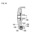
- compressors for vehicle air conditioners are known that are provided with a rotation detecting mechanism in order to detect rotation malfunctions due to seizing and the like.
- a rotation detecting mechanism in this rotation detecting mechanism, a through hole 102 is formed in a non-magnetic housing member 101, and a detecting sensor 104 is mounted in this through hole 102 via an O-ring 103.
- the change in the magnetic flux that flows from the magnet 106 to the core 107 accompanying the rotation of a detected body 105 is converted to a voltage by a pickup coil 108, and the detecting sensor 104 detects the result as the rotational state.
- JP-A-H8-319944 disclose structures that provide a detector on the outside of the compressor body, and forms a circulating magnetic circuit by causing a leakage magnetic flux from an electromagnetic clutch to be conducted in sequence from the drive shaft, to a rotating substrate (detected body) that moves in cooperation with this drive shaft, and then to bolts (fastening fixtures) that hold the compressor body together. Changes in the magnetic flux between a bolt and the rotating substrate occur due to the periodic movement of the rotating substrate. These changes in magnetic flux are then detected by the detector, and the rotation speed of the compressor is detected based on the detected result. Thereby, there is the advantage that it is possible to achieve a high detection accuracy with a simple structure.
- JP-AH8-319944 provides a permanent magnet for amplifying the magnetic flux changes in the housing member in proximity to the detector. Thereby, there is the advantage that it is possible to attain a higher detection accuracy than Japanese Patent Application Publication No. JP-A-H6-299960 .
- the magnetic sensor is placed at the head portion of the fastening fixtures or on the stator side of an electromagnetic clutch that is opposite to the fastening fixtures, and there is a problem in that the overall length of the compressor in the axial direction is increased due to the space for the sensor installation.
- the shape of the housing member is changed in order to provide the permanent magnet, and thus a new magnetic flux generating source is necessary.
- a strong and high cost magnet is necessary in order to amplify the magnetic flux, which takes the form of a large circulating magnetic flux circuit. For these reasons, there is the problem, for example, that the production cost of the compressor is increased.
- the present invention is described as follows.
- the rotation state of the compressor is detected by providing a permanent magnet on a drain bolt, which is normally provided, in order to form a circulating magnetic circuit via the drain bolt, and by detecting the magnetic flux changes in this circulating magnetic circuit from the outside of the housing member by using a magnetic sensor that is provided at the head portion of the drain bolt.
- the detecting device because it is possible to avoid the inclusion of contaminants that accompanies the placement of the detecting device, it is possible to provide a compact and inexpensively manufactured compressor.
- a circulating magnetic circuit which is due to the magnetic flux of a permanent magnet, is conducted through the detected body and the drain bolt, it is possible to form a stronger circulating magnetic circuit, and it is possible thereby to detect the magnetic flux changes in the circulating magnetic circuit more reliably.
- the permanent magnet is provided at the distal end of the drain bolt, it is possible to form a stronger circulating magnetic circuit, and it is possible thereby to detect the magnetic flux changes in the circulating magnetic circuit more reliably.
- the permanent magnet is provided at the head portion of the drain bolt, it is possible to form a stronger circulating magnetic circuit, and it is possible thereby to detect the magnetic flux changes in the circulating magnetic circuit more reliably.
- the detecting device is provided with a magnetic member that covers the head portion of the drain bolt, it is possible to form a stronger circulating magnetic circuit, and it is possible thereby to detect the magnetic flux changes in the circulating magnetic circuit more reliably.
- the magnetic flux from a magnet that is provided in a detected body forms a circulating magnetic circuit via a drain bolt
- the rotation state of the compressor is detected by detecting the magnetic flux changes in this circulating magnetic circuit from the outside of the housing member by using a magnetic sensor that is provided at the head portion of the drain bolt.
- the detecting device because it is possible to avoid the inclusion of contaminants that accompanies the placement of the detecting device, it is possible to provide thereby a compact and inexpensively manufactured compressor.
- a circulating magnetic circuit that is caused by the magnetic flux of a permanent magnet is conducted through the detected body and the drain bolt, it is possible to form a stronger circulating magnetic circuit, and it is possible thereby to detect the magnetic flux changes in the circulating magnetic circuit more reliably.
- the detecting device is provided with a magnetic member that covers the head portion of the drain bolt, it is possible to form a stronger circulating magnetic circuit, and it is possible thereby to detect the magnetic flux changes in the circulating magnetic circuit more reliably.
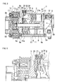
- compressor, 2 compressor body, 3; front housing, 4; cylinder block, 5; rear housing, 6; bolt member, 7; electromagnetic clutch, 8; drive shaft, 9; detected body, 11; piston, 20; magnetic sensor, 31; drain bolt hole, 32; drain bolt, 33; permanent magnet, and 34; yoke member.
- the compressor according to the present invention is provided with a housing member, a drive shaft, movable members, a detected body, a drain bolt hole, a drain bolt, and a detecting device, which will be described below. Furthermore, for example, the compressor can be further provided with a skew plate, which will be described below. Note that it is possible to select freely the compression configuration of the compressor, and examples thereof include reciprocating-type, scroll-type, screw-type, or vane-type compressors.
- housing member The material, shape, and number and the like of the "housing member" described above are not limited in particular on the condition that the body of the compressor can be formed by combining a plurality of members.
- This housing member may be made of, for example, a non-magnetic body.
- examples of a housing member can include a front housing, a cylinder block, and a rear housing and the like.
- the material, shape, and length and the like of the "drive shaft” described above are not limited in particular on the conditions that the drive shaft can be inserted into the compressor body and can be linked to a drive power source via an electromagnetic clutch.
- This drive shaft is normally supported so as to rotate freely inside the compressor body.
- this drive shaft can be made of, for example, a magnetic body.
- the electromagnetic clutch is supported so as to rotate freely at the distal end side of a front housing, which normally serves as a housing member.
- examples of the drive power source include an internal combustion engine, an electrical motor, and the like.
- movable members are not limited in particular on the conditions that the movable members move in cooperation with the drive shaft and they are able to carry out the compression of a fluid.
- These movable members may be appropriately used depending on the compression configuration and the like of the compressor, and examples include piston-type, scroll-type, screw-type, and vane-type compressors.
- the material, shape, and movement configuration and the like of the "detected body” are not limited in particular on the condition that the detected body can move in cooperation with the drive shaft described above.
- This detected body can cause magnetic flux changes in a circulating magnetic circuit A (refer, for example, to FIG. 2 ) and a circulating magnetic circuit B (refer, for example, to FIG. 15 ), for example, by moving in cooperation with the drive shaft to produce changes in the gap between the detected body and the drain bolt.
- This circulating magnetic circuit A is formed by a magnetic flux, which is from a permanent magnet that is normally provided at a drain bolt, being conducted through the detected body and the drain bolt.
- the circulating magnetic circuit B is formed by a magnetic flux, which is from a permanent magnet that is normally provided at the detected body, being conducted through the detected body and the drain bolt.
- the detected body may be, for example, installed on the drive shaft and can rotate along with the drive shaft.
- this detected body can, for example, be made of a magnetic body.
- this detected body may be, for example, formed into a disk shape, and one or more reduced diameter portions or increased diameter portions may be formed on the outer circumferential side thereof in order to generate magnetic flux changes.
- the detected body may be disposed, for example, between the electromagnetic clutch and the movable members. From the viewpoint of detection precision, preferably this detected body is disposed at a position that is in proximity to the electromagnetic clutch inside the front housing, which serves as the housing member.
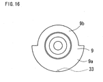
- a permanent magnet is installed on the detected body, as shown, for example, in FIG. 15 and FIG. 16 , preferably a permanent magnet 33 is provided at the circumferential edge side of a detected body 9.
- the term "circumferential edge side" denotes not only providing a permanent magnet along the circumferential edge of the detected body 9, but also denotes, as shown in FIG. 17 and FIG. 18 , providing a permanent magnet more toward the inside than the circumferential edge of the detected body.
- the "drain bolt hole” described above is a threaded through hole that is provided in the housing (below, the front housing) at a position in proximity to the detected body, and is a hole that is normally provided in order to inject a fluid into the compressor or to drain the fluid.
- the size of the drain bolt hole may be a normally used size, and is not limited in particular.
- the position of the drain bolt hole should allow detecting the magnetic flux changes due to the position of the detected body. Examples of such a position include the front housing that is positioned at the circumferential edge of the detected body.
- the "drain bolt” described above is a bolt that is normally provided by being screwed into the drain bolt hole in order to seal the hole.
- the material and shape and the like of the drain bolt are not limited in particular on the condition that the drain bolt is a magnetic body.
- the position at which the permanent magnet 33 is provided at the drain bolt and the method by which the permanent magnet 33 is provided at the drain bolt are not limited in particular.
- a bottomed hole may be provided, for example, in the distal end (refer, for example, to FIG. 2 and FIG. 11 ) or the head portion (refer, for example, to FIG. 8 ) of the drain bolt, and the permanent magnet 33 may be inserted and attached therein.
- the permanent magnet 33 may be attached to the distal end (refer, for example, to FIG.
- the permanent magnet 33 may be provided at the circumference of the drain bolt (refer, for example, to FIG. 12 ).
- the permanent magnet 33 may be embedded in the drain bolt (not illustrated).
- examples of a disposition method include attaching by fitting, by adhesion, or by the magnetic force of the permanent magnet itself.
- a yoke member 34 made of a magnetic member that covers the head portion of the drain bolt may be installed, and the permanent magnet 33 may be provided in this yoke member 34.
- the "detecting device” described above detects the rotation state of the drive shaft by detecting the magnetic flux changes in the circulating magnetic circuits A and B that are due to the detected body.
- This detecting device is structured by a magnetic sensor.
- the shape, size, and number and the like of the "magnetic sensor” described above are not limited in particular on the condition that the magnetic sensor is provided at the head portion of the drain bolt.
- the type of the magnetic sensor is not limited in particular, and examples include a pickup coil, a Hall element, and the like.
- this magnetic sensor may be disposed such that, for example, the magneto-sensitive direction P is aligned in a direction that is perpendicular to the axial direction of compressor body (refer to FIG. 2 and FIG. 3 ), or can be disposed such that this magneto-sensitive direction P is aligned in the axial direction of compressor body (refer to FIG. 4 ).
- the term "proximity" described above denotes a position at which a change in the magnetic flux, which is caused by the gap between the detected body and the drain bolt changing, can be detected when the detected body rotates.
- the material, shape, and movement configuration of the "skew plate” is not limited in particular on the condition that the skew plate can move in cooperation with the drive shaft.
- This skew plate is normally supported by the drive shaft so as to tilt freely, and accompanying the rotation of the drive shaft, the skew plate tilts with respect to the drive shaft to move the movable members.
- the compressor according to the present invention is illustrated by a variable displacement compressor for a vehicle air conditioner that is provided with a detecting device on the head portion of a drain bolt and in which the compression capacity changes depending on the change of the tilt of the skew plate, which will be described below.
- a compressor 1 has a body 2 that includes a tubular aluminum (non-magnetic body) front housing 3, a cylinder block 4, and a rear housing 5 (provided as an example of the "housing member" according to the present invention). While the back end of the front housing 3 abuts the front end of this cylinder block 4 and the front end of the rear housing 5 abuts the back end of the cylinder block 4 via a valve plate 12, the threaded portions (not illustrated) of a plurality of bolt members 6 made of a ferrous metal (magnetic body) are screwed into the rear housing 5, and a head portion 6a of each of the bolt members 6 is secured to the outer end surface of the front housing 3. Thereby, the front housing 3, the cylinder block 4, and the rear housing 5 are joined together integrally.
- This drive shaft 8 is supported so as to rotate freely inside the cylinder block 4 and the front housing 3 via a bearing.
- a disk-shaped ferrous metal (magnetic body) detected body 9 is attached to this drive shaft 8. This detected body 9 is positioned between the electromagnetic clutch 7 and the pistons, which will be described below, and is disposed at a position in proximity to the electromagnetic clutch 7 inside the front housing 3.
- an increased diameter portion 9a and a reduced diameter portion 9b having a predetermined interval (180 degrees) are formed in the circumferential direction on the outer circumferential side of this detected body 9 in order to generate the magnetic flux changes in the circulating magnetic circuit that are caused by the rotation (refer to FIG. 3 ), which will be disclosed below (refer to FIG. 3 ).
- a skew plate 10 is provided so as to tilt freely on the drive shaft 8, and this skew plate 10 is guided by a guiding portion 9c of the rotating detected body 9 so as to tilt within a predetermined angle range.
- the front housing 3 has a drain bolt hole 31 and a drain bolt 32 that is screwed into this drain bolt hole 31.
- the position of the drain bolt hole 31 in the axial direction with respect to compressor body 2 is located opposed to the detected body 9 in the radial direction.
- a permanent magnet 33 is provided at the distal end of the drain bolt 32. The position of this permanent magnet 33 is located at a distance that enables detecting the changes in magnetic flux that are caused by the gap between the circumferential edge of the detected body 9 and the drain bolt 32 changing when the detected body 9 rotates.
- Pistons 11 are supported so as to move freely in the axial direction of compressor body 2 inside a plurality of cylinder chambers 4a that are formed in the cylinder block 4.
- the outer circumferential end portions of the skew plate 10 are linked to the linking portions 11a that are formed on the front sides of these pistons 11. Therefore, the skew plate 10 tilts to impart a reciprocating movement to these pistons 11 inside the cylinder chambers 4a due to the rotation of the drive shaft 8 and the detected body 9.
- the electromagnetic clutch 7 is supported so as to rotate freely via a bearing on a boss portion 3b of the front housing 3.
- This electromagnetic clutch 7 is structured by being provided with a pulley 13 that is linked to the crank pulley of the engine (provided as an example of the "power source” according to the present invention) via a V-belt (not illustrated); a rotor 14 that is attached to the inner circumferential side of the pulley 13; a stator 16 that is attached to this rotor 14 and has an electromagnetic coil 15 built therein; a disc-shaped armature 17 that is disposed opposed to the conducting friction surface of this rotor 14; and a hub 18 that couples this armature 17 to the drive shaft 8.
- a magnetic sensor 20 (provided as an example of the "detecting device” according to the present invention) that can detect magnetic flux changes is formed on the outside surface of the front housing 3 and is provided at the head portion of the drain bolt 32.
- This magnetic sensor 20 has an element 21 that is made of a pickup coil or the like.
- this magnetic sensor 20 is disposed such that the magneto-sensitive direction P thereof is orthogonal to the axial direction of the compressor body 2.
- a circulating magnetic circuit A (shown by the dashed line in the figure) is formed by the magnetic flux from the permanent magnet 33 being conducted through the detected body 9 and the drain bolt 32.
- the skew plate 10 is tilted by the rotation of the detected body 9 to impart a reciprocating movement to the pistons 11 in the cylinder chambers 4a, the coolant gas, which flows from the intake chamber 5a of the rear housing 5 into the cylinder chamber 4a, is compressed, and this compressed gas is discharged into the discharge chamber 5b of the rear housing 5.
- the circulating magnetic circuit A (refer to FIG. 2 ) is formed by the magnetic flux of the permanent magnet 33.
- the detected body 9 is provided with locations at which the diameter differs (refer to FIG. 3 ).
- the gap (air gap) between the permanent magnet 33 and the detected body 9 changes, and the magnetic flux density of the circulating magnetic circuit A is thereby changed.
- the output voltage of the magnetic sensor 20, which is detecting the magnetic flux changes in the circulating magnetic circuit A changes, it is possible to detect the rotation state of the compressor 1 based on this change in the output voltage.
- the compressor 1 is structured by providing the magnetic sensor 20 at the head portion of the drain bolt 32, which is on the outside surface of the front housing 3 that forms the compressor body 2.
- the circulating magnetic circuit A is formed by a magnetic flux from the permanent magnet 33 being conducted through the detected body 9 and the drain bolt 32, and the magnetic sensor 20 detects the rotating state of the compressor 1 by detecting the magnetic flux changes in this circulating magnetic circuit A from the outside surface of the front housing 3.
- the compressor according to the present invention is exemplified by a variable displacement compressor for a vehicle air conditioner that is provided with a magnetic member that covers the head portion of the drain bolt and in which the compression capacity changes depending on the change of the tilt of the skew plate, which will be described below.
- the compressor 1 according to the second embodiment is provided with a structure that is similar to the first embodiment, and differs in being provided with the yoke member 34, which is a magnetic member according to the present invention.
- This yoke member 34 is provided on the head portion of the drain bolt 32 along with the magnetic sensor 20, and is provided with a shape that is in contact with the portion of the head portion of the drain bolt 32 that is not covered by the magnetic sensor 20.
- the yoke member 34 is made of a ferrous metal, which is a magnetic body.
- such a yoke member 34 strengthens the coupling between the magnetic sensor 20 and the drain bolt 32, which are portions of the circulating magnetic circuit A, and can further strengthen the capacity of the magnetic sensor 20 to detect the magnetic flux changes.
- it is possible to detect the magnetic flux changes that are due to the rotation of the detected body 9 even if a permanent magnet is used that has a weaker magnetic power and is inexpensive, and it is possible thereby to suppress the production costs further.
- the compressor according to the present invention is exemplified by a variable displacement compressor for a vehicle air conditioner that is provided with a magnetic member that covers the head portion of the drain bolt and in which the compression capacity changes depending on the change of the tilt of the skew plate, which will be described below.
- the compressor 1 according to third embodiment is provided with a structure that is similar to the first embodiment, and differs in that the placement position for the permanent magnet 33 that is embedded in the head portion of the drain bolt 32. In this manner, similar to the first embodiment, in the third embodiment as well, in which a placement position for the permanent magnet 33 that is embedded in the head portion of the drain bolt 32, it is possible to detect the magnetic flux changes that are due to the rotation of the detected body 9.
- the compressor according to the present invention is exemplified by a variable displacement compressor for a vehicle air conditioner that is provided with a permanent magnet on the circumferential edge side of the detected body 9, and in which the compression capacity changes depending on the change in the tilt of the skew plate, which will be described below.
- the compressor 1 according to fourth embodiment is provided with a structure that is similar to the first embodiment, and differs in that the placement position for the permanent magnet 33 that is embedded in the circumferential edge side of the detected body 9. In this manner, as shown in FIG.
- the circulating magnetic circuit B (shown by the dashed line in the figure) is formed due to the magnetic flux from the permanent magnet 33 being conducted through the detected body 9 and the drain bolt 32.
- the magnetic sensor 20 is disposed such that the magneto-sensitive direction P is aligned with the axial direction of the compressor body 2 of the compressor 1.
- the element 21 in the magnetic sensor 20 may be disposed such that the magneto-sensitive direction P is aligned with a direction that is substantially orthogonal to the axial direction of compressor body 2 of the compressor 1, or is aligned at a predetermined angle.
- a detected body 9 that includes an increased diameter portion 9a and a reduced diameter portion 9b pair was provided as an example.
- a plurality of concave portions (or reduced diameter portions) may be formed at predetermined intervals along the circumferential direction on the outer circumferential side of the detected body 9.
- the compressor of the present invention is used as a compressor for a vehicle.
- the compressor of the present invention is advantageously used as a compressor for a vehicle air conditioner.
- This compressor includes housing members that form a body; a drive shaft linked to a drive power source via an electromagnetic clutch; movable members moving in cooperation with the drive shaft and carrying out the compression of a fluid; a detected body moving in cooperation with the drive shaft; a drain bolt screwed into a drain bolt hole provided in a housing member in proximity to the detected body; and a detecting device detecting the rotation state of the drive shaft by the detected body.
- the drain bolt is provided with a permanent magnet
- the detecting device is structured by a magnetic sensor that includes a magnetic impedance element, and the magnetic sensor is provided at the head portion of the drain bolt.
Landscapes
- Engineering & Computer Science (AREA)
- Mechanical Engineering (AREA)
- General Engineering & Computer Science (AREA)
- Compressors, Vaccum Pumps And Other Relevant Systems (AREA)
- Compressor (AREA)
- Control Of Positive-Displacement Pumps (AREA)
- Applications Or Details Of Rotary Compressors (AREA)
Applications Claiming Priority (1)
| Application Number | Priority Date | Filing Date | Title |
|---|---|---|---|
| JP2006356803A JP4803027B2 (ja) | 2006-12-29 | 2006-12-29 | コンプレッサ |
Publications (2)
| Publication Number | Publication Date |
|---|---|
| EP1939449A2 true EP1939449A2 (fr) | 2008-07-02 |
| EP1939449A3 EP1939449A3 (fr) | 2011-04-06 |
Family
ID=39154237
Family Applications (1)
| Application Number | Title | Priority Date | Filing Date |
|---|---|---|---|
| EP07119094A Withdrawn EP1939449A3 (fr) | 2006-12-29 | 2007-10-23 | Compresseur |
Country Status (3)
| Country | Link |
|---|---|
| US (1) | US20080159878A1 (fr) |
| EP (1) | EP1939449A3 (fr) |
| JP (1) | JP4803027B2 (fr) |
Cited By (2)
| Publication number | Priority date | Publication date | Assignee | Title |
|---|---|---|---|---|
| EP2372153A1 (fr) * | 2010-03-17 | 2011-10-05 | Valeo Compressor Europe, s.r.o. | Geschwindigkeitssensor |
| EP3358185A1 (fr) * | 2017-02-03 | 2018-08-08 | Okenseiko Co., Ltd. | Pompe a diaphragme |
Families Citing this family (5)
| Publication number | Priority date | Publication date | Assignee | Title |
|---|---|---|---|---|
| KR100943994B1 (ko) | 2009-07-10 | 2010-02-26 | 주식회사 성진엠텍 | 소화가스 교반 송풍기의 압축기 |
| CN102937431B (zh) * | 2012-10-29 | 2015-07-15 | 昆山市力格自动化设备有限公司 | 一种汽车压缩机后端盖垫片距离测试治具 |
| KR102582391B1 (ko) * | 2016-12-29 | 2023-09-26 | 한온시스템 주식회사 | 압축기 |
| JP6868703B2 (ja) * | 2017-03-24 | 2021-05-12 | ハンオン システムズ | 圧縮機 |
| DE102017220256A1 (de) | 2017-11-14 | 2019-05-16 | Mahle International Gmbh | Axialkolbenmaschine zur Regulierung einer Kraftfahrzeugklimatisierung |
Citations (2)
| Publication number | Priority date | Publication date | Assignee | Title |
|---|---|---|---|---|
| US4355959A (en) | 1979-10-26 | 1982-10-26 | Kabushiki Kaisha Toyoda Jidoshokki Seisakusho | Rotation sensor of a swash-plate type compressor |
| GB2194821A (en) | 1986-09-04 | 1988-03-16 | Sanden Corp | Refrigerant compressor |
Family Cites Families (15)
| Publication number | Priority date | Publication date | Assignee | Title |
|---|---|---|---|---|
| US2365309A (en) * | 1943-07-12 | 1944-12-19 | Robert E Barry | High-pressure pump |
| US2622942A (en) * | 1947-04-24 | 1952-12-23 | Munoz Alfred | Compressor |
| US3687233A (en) * | 1970-07-23 | 1972-08-29 | Garrett Corp | Integral lubrication system |
| JPS57139677U (fr) * | 1981-02-26 | 1982-09-01 | ||
| JPS5882082A (ja) * | 1981-11-11 | 1983-05-17 | Toyoda Autom Loom Works Ltd | 斜板式圧縮機における異常検出機構 |
| US4561223A (en) * | 1983-02-03 | 1985-12-31 | Defender Energy Of Connecticut, Inc. | Panel fastener system and retaining member |
| DE3347307A1 (de) * | 1983-12-28 | 1985-07-11 | Speck-Kolbenpumpen-Fabrik Otto Speck Kg, 8192 Geretsried | Plungerpumpe |
| JPS63191914A (ja) * | 1987-02-05 | 1988-08-09 | Fuji Koki Seisakusho:Kk | 圧縮機駆動部の回転検出装置 |
| JPH0245688A (ja) * | 1988-08-05 | 1990-02-15 | Hitachi Ltd | 回転式圧縮機の回転数検出機構 |
| US5027755A (en) * | 1990-05-24 | 1991-07-02 | Henry Jr Weston W | Wobble plate internal combustion engine |
| US5540560A (en) * | 1993-04-14 | 1996-07-30 | Kabushiki Kaisha Toyoda Jidoshokki Seisakusho | Compressor with rotation detecting mechanism |
| JPH07259732A (ja) * | 1994-03-28 | 1995-10-09 | Calsonic Corp | コンプレッサにおける回転・温度検出装置 |
| US5465078A (en) * | 1995-02-23 | 1995-11-07 | Illinois Tool Works Inc. | Magnetic drain bolt |
| JPH08319944A (ja) * | 1995-05-26 | 1996-12-03 | Toyota Autom Loom Works Ltd | 圧縮機 |
| US7357225B2 (en) * | 2004-08-05 | 2008-04-15 | Dorian George P | Two part oil or fluid drain plug with magnet |
-
2006
- 2006-12-29 JP JP2006356803A patent/JP4803027B2/ja not_active Expired - Fee Related
-
2007
- 2007-10-23 EP EP07119094A patent/EP1939449A3/fr not_active Withdrawn
- 2007-12-06 US US11/951,686 patent/US20080159878A1/en not_active Abandoned
Patent Citations (2)
| Publication number | Priority date | Publication date | Assignee | Title |
|---|---|---|---|---|
| US4355959A (en) | 1979-10-26 | 1982-10-26 | Kabushiki Kaisha Toyoda Jidoshokki Seisakusho | Rotation sensor of a swash-plate type compressor |
| GB2194821A (en) | 1986-09-04 | 1988-03-16 | Sanden Corp | Refrigerant compressor |
Cited By (7)
| Publication number | Priority date | Publication date | Assignee | Title |
|---|---|---|---|---|
| EP2372153A1 (fr) * | 2010-03-17 | 2011-10-05 | Valeo Compressor Europe, s.r.o. | Geschwindigkeitssensor |
| EP2372155A3 (fr) * | 2010-03-17 | 2012-02-01 | Valeo Compressor Europe, s.r.o. | Système à sécurité intégrée d'embrayage |
| EP2372154A3 (fr) * | 2010-03-17 | 2012-02-01 | Valeo Compressor Europe, s.r.o. | Capteur de vitesse |
| EP3358185A1 (fr) * | 2017-02-03 | 2018-08-08 | Okenseiko Co., Ltd. | Pompe a diaphragme |
| CN108386345A (zh) * | 2017-02-03 | 2018-08-10 | 应研精工株式会社 | 隔膜泵 |
| CN108386345B (zh) * | 2017-02-03 | 2019-10-25 | 应研精工株式会社 | 隔膜泵 |
| US10550832B2 (en) | 2017-02-03 | 2020-02-04 | Okenseiko Co., Ltd. | Diaphragm pump |
Also Published As
| Publication number | Publication date |
|---|---|
| US20080159878A1 (en) | 2008-07-03 |
| JP2008163914A (ja) | 2008-07-17 |
| JP4803027B2 (ja) | 2011-10-26 |
| EP1939449A3 (fr) | 2011-04-06 |
Similar Documents
| Publication | Publication Date | Title |
|---|---|---|
| EP1939449A2 (fr) | Compresseur | |
| US5540560A (en) | Compressor with rotation detecting mechanism | |
| KR100212525B1 (ko) | 압축기 | |
| JP6514406B2 (ja) | 電気的な駆動モータを備えた自動車の補助装置 | |
| US4502853A (en) | Rotational speed sensor for vane compressors | |
| CN103683601B (zh) | 电动马达及电动泵 | |
| US7785079B2 (en) | Compressor and method of using compressor | |
| KR102130409B1 (ko) | 압축기 | |
| US11143174B2 (en) | Compressor | |
| US20070017771A1 (en) | Rotating machine having electro-magnetic clutch | |
| EP0508823B1 (fr) | Compresseur à plateau en biais avec dispositif à déplacement variable | |
| JP4652225B2 (ja) | コンプレッサ | |
| CN217415733U (zh) | 用于制动系统的泵系统 | |
| JPH0424662B2 (fr) | ||
| WO2011078016A1 (fr) | Compresseur à aubes | |
| GB2156906A (en) | Fluid compressor | |
| JPH0335891Y2 (fr) | ||
| JP2687835B2 (ja) | 圧縮機 | |
| JPS625659Y2 (fr) | ||
| KR102198516B1 (ko) | 압축기 | |
| JP2000249062A (ja) | 圧縮機に接続される線状部品の固定構造及び固定方法 | |
| JP3296512B2 (ja) | 圧縮機 | |
| JPH0533741Y2 (fr) | ||
| JPH0245688A (ja) | 回転式圧縮機の回転数検出機構 | |
| KR0139930Y1 (ko) | 압축기의 회전속도 검출장치 |
Legal Events
| Date | Code | Title | Description |
|---|---|---|---|
| PUAI | Public reference made under article 153(3) epc to a published international application that has entered the european phase |
Free format text: ORIGINAL CODE: 0009012 |
|
| 17P | Request for examination filed |
Effective date: 20071023 |
|
| AK | Designated contracting states |
Kind code of ref document: A2 Designated state(s): AT BE BG CH CY CZ DE DK EE ES FI FR GB GR HU IE IS IT LI LT LU LV MC MT NL PL PT RO SE SI SK TR |
|
| AX | Request for extension of the european patent |
Extension state: AL BA HR MK RS |
|
| PUAL | Search report despatched |
Free format text: ORIGINAL CODE: 0009013 |
|
| AK | Designated contracting states |
Kind code of ref document: A3 Designated state(s): AT BE BG CH CY CZ DE DK EE ES FI FR GB GR HU IE IS IT LI LT LU LV MC MT NL PL PT RO SE SI SK TR |
|
| AX | Request for extension of the european patent |
Extension state: AL BA HR MK RS |
|
| 17Q | First examination report despatched |
Effective date: 20111114 |
|
| AKX | Designation fees paid |
Designated state(s): DE FR GB |
|
| GRAP | Despatch of communication of intention to grant a patent |
Free format text: ORIGINAL CODE: EPIDOSNIGR1 |
|
| INTG | Intention to grant announced |
Effective date: 20160126 |
|
| STAA | Information on the status of an ep patent application or granted ep patent |
Free format text: STATUS: THE APPLICATION IS DEEMED TO BE WITHDRAWN |
|
| 18D | Application deemed to be withdrawn |
Effective date: 20160607 |