EP1939923A2 - Probenhalter für ein Elektronenmikroskop - Google Patents
Probenhalter für ein Elektronenmikroskop Download PDFInfo
- Publication number
- EP1939923A2 EP1939923A2 EP07255043A EP07255043A EP1939923A2 EP 1939923 A2 EP1939923 A2 EP 1939923A2 EP 07255043 A EP07255043 A EP 07255043A EP 07255043 A EP07255043 A EP 07255043A EP 1939923 A2 EP1939923 A2 EP 1939923A2
- Authority
- EP
- European Patent Office
- Prior art keywords
- specimen
- holder
- plate member
- view
- retainer
- Prior art date
- Legal status (The legal status is an assumption and is not a legal conclusion. Google has not performed a legal analysis and makes no representation as to the accuracy of the status listed.)
- Granted
Links
- 238000010894 electron beam technology Methods 0.000 claims description 6
- 238000000034 method Methods 0.000 description 4
- 238000003325 tomography Methods 0.000 description 2
- 239000004020 conductor Substances 0.000 description 1
- 238000003780 insertion Methods 0.000 description 1
- 230000037431 insertion Effects 0.000 description 1
- 230000033001 locomotion Effects 0.000 description 1
Images




Classifications
-
- H—ELECTRICITY
- H01—ELECTRIC ELEMENTS
- H01J—ELECTRIC DISCHARGE TUBES OR DISCHARGE LAMPS
- H01J37/00—Discharge tubes with provision for introducing objects or material to be exposed to the discharge, e.g. for the purpose of examination or processing thereof
- H01J37/02—Details
- H01J37/20—Means for supporting or positioning the object or the material; Means for adjusting diaphragms or lenses associated with the support
-
- H—ELECTRICITY
- H01—ELECTRIC ELEMENTS
- H01J—ELECTRIC DISCHARGE TUBES OR DISCHARGE LAMPS
- H01J2237/00—Discharge tubes exposing object to beam, e.g. for analysis treatment, etching, imaging
- H01J2237/20—Positioning, supporting, modifying or maintaining the physical state of objects being observed or treated
- H01J2237/202—Movement
- H01J2237/20207—Tilt
-
- H—ELECTRICITY
- H01—ELECTRIC ELEMENTS
- H01J—ELECTRIC DISCHARGE TUBES OR DISCHARGE LAMPS
- H01J2237/00—Discharge tubes exposing object to beam, e.g. for analysis treatment, etching, imaging
- H01J2237/26—Electron or ion microscopes
- H01J2237/2611—Stereoscopic measurements and/or imaging
Definitions
- the present invention relates to a specimen holder for use with an electron microscope (EM) and, more particularly, to an EM specimen holder capable of obtaining a specimen image even at high tilt angles.
- EM electron microscope
- tomography that is a three-dimensional image reconstruction technique has attracted attention chiefly in biological fields.
- images of a tilted specimen are processed. If the amount of information about the specimen is increased, a more accurate three-dimensional image can be built.
- the present invention relates to an EM specimen holder used for acquisition of the information.
- Fig. 5 shows the outer appearance of a prior-art specimen holder for use with an electron microscope.
- the whole holder is shown.
- the body of the specimen holder is indicated by numeral 1.
- the holder has a handle 2.
- a retainer (specimen-holding portion) 3 for holding a specimen 4 is mounted at the front end of the body 1 of the holder.
- the specimen 4 is held to the retainer 3.
- the body 1 of the specimen holder has a tilt axis 5.
- the body 1 of the specimen holder is mounted to a goniometer (not shown) for an electron microscope.
- the body 1 of the holder is tilted about the tilt axis 5 by the tilting mechanism of the goniometer. Directions of tilt are indicated by the arrows A.
- the specimen holder is tilted in a clockwise direction and in a counterclockwise direction.
- Fig. 6 is an explodedperspective viewof the prior-art retainer. In both Figs. 5 and 6 , like components are indicated by like reference numerals.
- a plate member 10 is used to attach the specimen 4 having a diameter of about 3.0 to 3.2 mm and a thickness of about 50 ⁇ m.
- a hole 10a is formed around the front end of the plate member 10. The hole 10a provides a reference in searching the whole specimen for a desired field of view.
- a circular groove 10b is formed around the front end of the plate member 10 and used to determine the position of the specimen.
- a notch 10c is formed at the foremost end of the plate member 10 and offers an insertion port into which the front ends of tweezers are inserted when the specimen is taken out.
- a leaf spring 11 is used to hold down the specimen 4.
- the leaf spring 11 is mounted into a threaded hole 10d formed in the plate member 10 by a screw 12.
- a method of holding the specimen with the retainer constructed as described so far is next described.
- the specimen 4 is placed along the circular groove 10b formed in the plate member 10. Then, the leaf spring 11 is held to the plate member 10 with the spring 12. As a result, the specimen 4 is held to the plate member 10 by the force of the leaf spring 11.
- a known device of this kind uses a cartridge whose body has a front-end portion in which a meshed portion is formed. A slice of a specimen is picked up by this meshed portion (see, for example, patent reference 1). Furthermore, a holder for carrying a slice of a specimen while maintaining it at a low temperature is known (see, for example, patent reference 2).
- the slice of the specimen includes a specimen slice grid made of a thermally conductive material.
- the specimen slice grid has plural grid bars intersecting each other so as to form grid openings.
- Each of the grid openings has a length and a width. The longitudinal direction of each grid opening is substantially perpendicular to the longitudinal axis of the holder body. The length of each grid opening is greater than the width of each grid opening.
- the slice of the specimen can be rotated through an angle of at least 90° in both directions from the horizontal direction.
- Patent reference 1 JP-A-8-17381 (paragraph 0010; Figs. 1 and 2 ).
- Patent reference 2 Japanese Patent No. 3, 605, 119 (from page 4, line 32 to page 5, line 4; Fig. 1 )
- Figs. 7(a)-7(d) illustrate the effective field of view when the prior-art retainer is tilted.
- like components are indicated by like reference numerals.
- the direction in which the retainer is observed is shown in Fig. 7(b).
- Fig. 7(a) shows the state in which the tilt angle is 0°.
- the specimen 4 is placed on the plate member 10. The specimen 4 is held from above with the leaf spring 11. When an electron beam EB is directed at the specimen from above it, an image B is focused onto a fluorescent screen.
- the diameter of the effective field of view is 2 mm.
- Fig. 7(c) shows the state in which the tilt angle is 80°.
- the field of vision is blocked by the leaf spring 11 and by the wall defining the circular groove 10b.
- the image on the fluorescent screen is invisible.
- the present invention has been made. It would be desirable to provide an EM specimen holder which permits a field of view to be obtained at a tilt angle that is made as close as possible to 90° and which can be manipulated easily.
- a first embodiment of the present invention provides a specimen holder which is for use with an electron microscope and which includes a holder body having a specimen-holding portion at the front end of the holder body.
- the specimen-holding portion has a plate member provided with a hole to permit passage of an electron beam.
- a groove is formed around the hole formed in the plate member to permit the specimen to be placed in position. The groove has cutouts lying perpendicularly to the tilted axis of the specimen holder.
- an (annular) recess is formed around the hole.
- the recess has a recess wall for holding a specimen in place.
- the recess wall has cut-outs or notches removed from it. The cut-outs are on either side of a tilt axis of the specimen holder.
- a second embodiment of the present invention is based on the first embodiment and further characterized in that the width of a specimen-installing portion taken perpendicularly to the tilted axis of the specimen holder is smaller than the diameter of the specimen.
- a field of view can be obtained at a tilt angle that is made as close as possible to 90° by cutting away any members lying perpendicularly to the tilt axis at the specimen position.
- the specimen can be taken out with improved ease of handling.
- Fig. 1 is a perspective view of a retainer according to one embodiment of the present invention, showing the outer appearance of the retainer.
- the retainer generally indicated by reference numeral 20
- the retainer 20 is held to the body of a specimen holder by the same method as in the related art.
- a specimen 4 a plate member 15, a leaf spring 11', and a screw 12 for holding the leaf spring 11' to the plate member 15.
- the retainer 20 has a specimen-installing portion 21 around its front end.
- the specimen 4 is greater than the specimen-installing portion 21. Because the part of the specimen-holding portion is smaller than the specimen in this way, the specimen 4 can be easily held between tweezers. Consequently, the specimen can be removed with improved ease of handling.
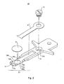
- Fig. 2 is an exploded perspective view of the retainer shown in Fig. 1 , the retainer being built according to one embodiment of the invention.
- the plate member 15 is used to attach the specimen 4 having a diameter of about 3.0 to 3.2 mm and a thickness of about 50 ⁇ m.
- a hole 15a permitting passage of an electron beam is formed around the front end of the plate member 15.
- the hole 15a provides a reference in searching the whole specimen for a desired field of view.
- a circular groove 15b is formed around the front end of the plate member 15, and is used to determine the position of the specimen.
- the groove 15b is formed around the hole 15a.
- the groove 15b has cutouts 16a and 16b.
- An arcuate member 15c is formed at the foremost end of the plate member 15.
- the width w of the arcuate member 15c is made smaller than the diameter of the specimen to eliminate all parts (corresponding to the cutouts 16a and 16b) which would otherwise constitute obstacles during tilting.
- the portions (corresponding to the cutouts 16a and 16b) lying perpendicularly to the tilt axis 5 (see Fig. 5 ) of the specimen holder are cut away.
- the specimen 4 can be picked up easily with tweezers from the cutouts 16a and 16b.
- the hole 15a, circular groove 15b, and arcuate member 15c together form the specimen-installing portion 21.
- the width w of the specimen-installing portion 21 taken perpendicularly to the tilt axis 5 (see Fig. 5 ) of the specimen holder is smaller than the diameter of the specimen 4.
- a leaf spring 11' is used to hold down the specimen 4, and has a claw-shaped front end.
- the leaf spring 11' is mounted with the screw 12 in a threaded hole 10d formed in the plate member 15. A method of holding the specimen by the device constructed in this way is next described.
- the specimen 4 is placed along the circular groove 15b formed in the plate member 15. Then, the leaf spring 11' is held to the plate member 15 with the screw 12. As a result, the specimen 4 is held to the plate member 15 by the force of the leaf spring 11'.
- any members (corresponding to the cutouts 16a and 16b in Fig. 2 ) lying perpendicularly to the tilt axis at the position of the specimen are cut away. Because of this structure, a field of view can be obtained at a tilt angle that is made as close as possible to 90°. Furthermore, according to embodiments of the present invention, the specimen can be taken out with improved ease of handling.
- Fig. 3 is a perspective view of the retainer shown in Figs. 1 and 2 , but showing a different state. In both Figs. 2 and 3 , like components are indicated by like reference numerals.
- Fig. 3 shows the state in which the specimen 4 is installed on the retainer 20. It can be seen that because the specimen-installing portion 21 is smaller than the specimen 4, the specimen 4 can be taken out with improved ease of handling.
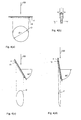
- Figs. 4(a)-4(d) illustrate an effective field of view when the retainer according to embodiments of the present invention is tilted.
- like components are indicated by like reference numerals.
- the leaf spring 11' is omitted because it does not affect blockage of the field of view.
- the direction in which the retainer is observed is indicated in Fig. 4(b).
- Fig. 4(a) shows the state in which the tilt angle is 0°.
- the specimen 4 is placed on the plate member 15.
- the specimen 4 is held down from above by the leaf spring 11' (not shown).
- An electron beam EB is directed from above the specimen.
- An image D is focused on the fluorescent screen.
- the diameter of the effective field of view is 2 mm.
- Fig. 4(d) shows the state in which the tilt angle is 80°. Also, in this case, member portions lying perpendicularly to the tilt axis at the specimen position are eliminated. Therefore, the field of vision is blocked neither by the leaf spring 11' nor by the wall defining the circular groove 15b.
- the image on the fluorescent screen is secured as indicated by F.
- the tweezers can be used with improved ease of handling.
- the specimen 4 can be placed in position easily and reliably in mounting the specimen.
- the specimen 4 can be withdrawn easily and reliably.
- the leaf spring 11' has the cutouts not to block the field of view, unlike the prior-art structure. However, rotation and positional deviation of the specimen can be suppressed because the specimen is held down reliably with the spring and because the cutouts are made angular.
Landscapes
- Chemical & Material Sciences (AREA)
- Analytical Chemistry (AREA)
- Sampling And Sample Adjustment (AREA)
Applications Claiming Priority (1)
| Application Number | Priority Date | Filing Date | Title |
|---|---|---|---|
| JP2006349195A JP2008159513A (ja) | 2006-12-26 | 2006-12-26 | 電子顕微鏡用試料ホルダー |
Publications (3)
| Publication Number | Publication Date |
|---|---|
| EP1939923A2 true EP1939923A2 (de) | 2008-07-02 |
| EP1939923A3 EP1939923A3 (de) | 2010-01-06 |
| EP1939923B1 EP1939923B1 (de) | 2012-02-22 |
Family
ID=39199943
Family Applications (1)
| Application Number | Title | Priority Date | Filing Date |
|---|---|---|---|
| EP07255043A Ceased EP1939923B1 (de) | 2006-12-26 | 2007-12-24 | Probenhalter für ein Elektronenmikroskop |
Country Status (3)
| Country | Link |
|---|---|
| US (1) | US7800077B2 (de) |
| EP (1) | EP1939923B1 (de) |
| JP (1) | JP2008159513A (de) |
Cited By (3)
| Publication number | Priority date | Publication date | Assignee | Title |
|---|---|---|---|---|
| EP2260286A4 (de) * | 2008-03-17 | 2012-04-11 | Protochips Inc | Präparathalter mit verwendung zur befestigung von proben in elektronenmikroskopen |
| AT510799A1 (de) * | 2010-11-29 | 2012-06-15 | Leica Microsystems Schweiz Ag | Halterung für einen elektronenmikroskopischen probenträger |
| US9312097B2 (en) | 2007-05-09 | 2016-04-12 | Protochips, Inc. | Specimen holder used for mounting samples in electron microscopes |
Families Citing this family (10)
| Publication number | Priority date | Publication date | Assignee | Title |
|---|---|---|---|---|
| KR20110114026A (ko) * | 2010-04-12 | 2011-10-19 | 삼성전자주식회사 | 시편 제조 장치 및 방법 |
| JP5532425B2 (ja) * | 2010-08-27 | 2014-06-25 | 株式会社日立ハイテクノロジーズ | 荷電粒子装置用試料ホルダ |
| JP5846931B2 (ja) * | 2012-01-25 | 2016-01-20 | 株式会社日立ハイテクノロジーズ | 電子顕微鏡用試料ホルダ |
| CN103531425A (zh) * | 2013-10-18 | 2014-01-22 | 上海华力微电子有限公司 | 一种透射电子显微镜样品的固定装置 |
| USD794816S1 (en) * | 2013-10-24 | 2017-08-15 | Hitachi High-Technologies Corporation | Sample holder for an electron microscope |
| EP3038131A1 (de) * | 2014-12-22 | 2016-06-29 | FEI Company | Verbesserter Probenhalter für Ladungsträgerteilchenmikroskop |
| CN108878238A (zh) * | 2018-05-25 | 2018-11-23 | 兰州大学 | 三维重构样品杆 |
| KR102080671B1 (ko) * | 2019-05-17 | 2020-02-25 | (주)이엠아이티 | 회전형 tem 시료 부착장치 및 그를 이용한 시료 가공방법 |
| WO2022073621A1 (en) * | 2020-10-09 | 2022-04-14 | Merck Patent Gmbh | Flexible sample holder for crystalline sponge |
| KR102649789B1 (ko) * | 2023-08-25 | 2024-03-22 | 한국표준과학연구원 | 전자 현미경용 교체형 샘플 홀더 |
Citations (2)
| Publication number | Priority date | Publication date | Assignee | Title |
|---|---|---|---|---|
| JPH0817381A (ja) | 1994-06-29 | 1996-01-19 | Jeol Ltd | 電子顕微鏡の試料装置 |
| JP3605119B2 (ja) | 1997-03-12 | 2004-12-22 | ガタン・インコーポレーテッド | 電子顕微鏡のための超高傾斜試験片低温移送ホルダ |
Family Cites Families (8)
| Publication number | Priority date | Publication date | Assignee | Title |
|---|---|---|---|---|
| US3575486A (en) * | 1969-08-25 | 1971-04-20 | Victor M De Posada | Specimen moving attachment for a microscope or the like |
| JPS58169762A (ja) * | 1982-03-30 | 1983-10-06 | Internatl Precision Inc | 電子線装置 |
| JPH04324240A (ja) * | 1991-04-25 | 1992-11-13 | Jeol Ltd | 電子顕微鏡用試料ホルダー及び試料保持法 |
| EP0504972A1 (de) * | 1991-03-18 | 1992-09-23 | Koninklijke Philips Electronics N.V. | Präparathalter zur Verwendung in einer Ladungsteilchenbündelanordnung |
| US5698856A (en) * | 1996-08-05 | 1997-12-16 | Frasca; Peter | Specimen holder for electron microscope |
| US6002136A (en) * | 1998-05-08 | 1999-12-14 | International Business Machines Corporation | Microscope specimen holder and grid arrangement for in-situ and ex-situ repeated analysis |
| US6388262B1 (en) * | 1998-08-12 | 2002-05-14 | Gatan, Inc. | Double tilt and rotate specimen holder for a transmission electron microscope |
| US7219565B2 (en) * | 2002-04-08 | 2007-05-22 | E.A. Fischione Instruments, Inc. | Specimen holding apparatus |
-
2006
- 2006-12-26 JP JP2006349195A patent/JP2008159513A/ja not_active Withdrawn
-
2007
- 2007-12-24 EP EP07255043A patent/EP1939923B1/de not_active Ceased
- 2007-12-26 US US11/964,392 patent/US7800077B2/en not_active Expired - Fee Related
Patent Citations (2)
| Publication number | Priority date | Publication date | Assignee | Title |
|---|---|---|---|---|
| JPH0817381A (ja) | 1994-06-29 | 1996-01-19 | Jeol Ltd | 電子顕微鏡の試料装置 |
| JP3605119B2 (ja) | 1997-03-12 | 2004-12-22 | ガタン・インコーポレーテッド | 電子顕微鏡のための超高傾斜試験片低温移送ホルダ |
Cited By (7)
| Publication number | Priority date | Publication date | Assignee | Title |
|---|---|---|---|---|
| US9312097B2 (en) | 2007-05-09 | 2016-04-12 | Protochips, Inc. | Specimen holder used for mounting samples in electron microscopes |
| EP2260286A4 (de) * | 2008-03-17 | 2012-04-11 | Protochips Inc | Präparathalter mit verwendung zur befestigung von proben in elektronenmikroskopen |
| US8513621B2 (en) | 2008-03-17 | 2013-08-20 | Protochips, Inc. | Specimen holder used for mounting |
| US8853646B2 (en) | 2008-03-17 | 2014-10-07 | Protochips, Inc. | Specimen holder used for mounting samples in electron microscopes |
| US8859991B2 (en) | 2008-03-17 | 2014-10-14 | Protochips, Inc. | Specimen holder used for mounting samples in electron microscopes |
| USRE48201E1 (en) | 2008-03-17 | 2020-09-08 | Protochips, Inc. | Specimen holder used for mounting samples in electron microscopes |
| AT510799A1 (de) * | 2010-11-29 | 2012-06-15 | Leica Microsystems Schweiz Ag | Halterung für einen elektronenmikroskopischen probenträger |
Also Published As
| Publication number | Publication date |
|---|---|
| JP2008159513A (ja) | 2008-07-10 |
| EP1939923B1 (de) | 2012-02-22 |
| EP1939923A3 (de) | 2010-01-06 |
| US7800077B2 (en) | 2010-09-21 |
| US20090014664A1 (en) | 2009-01-15 |
Similar Documents
| Publication | Publication Date | Title |
|---|---|---|
| EP1939923B1 (de) | Probenhalter für ein Elektronenmikroskop | |
| US10603089B2 (en) | Locking confirmation mechanism for a bone screw and plate assembly | |
| US6995380B2 (en) | End effector for supporting a microsample | |
| US5985680A (en) | Method and apparatus for transforming a substrate coordinate system into a wafer analysis tool coordinate system | |
| JP2000329664A (ja) | 透過型電子顕微鏡の観察方法および保持治具 | |
| EP1512957A2 (de) | Maske und diese verwendende Vorrichtung zur Vorbereitung von Proben durch Ionenbeschuss | |
| EP2930736A1 (de) | Probenhalter-Mikroschraubstock und Probenhaltersystem für Analysen mit gekoppelter Transmissionselektronenmikroskopie (TEM) und Atomsonden-Tomografie (APT) | |
| EP1684327A2 (de) | Probenhalter und Ionenstrahlverarbeitungssystem | |
| JP2008229779A (ja) | ピペット | |
| JP2001338599A (ja) | 荷電粒子線装置 | |
| US6677595B1 (en) | Specimen holder and spacer used in the same | |
| EP3474309B1 (de) | Dreidimensionales bildrekonstruktionsverfahren | |
| JP4784888B2 (ja) | Fibによるアトムプローブ分析用試料の作製方法とそれを実施する装置 | |
| US5077880A (en) | Tool for closing optical connectors having locking rings | |
| JP7414862B2 (ja) | 試料カートリッジ保持装置 | |
| JP2005294181A (ja) | バルク試料ホルダ | |
| JPH04324240A (ja) | 電子顕微鏡用試料ホルダー及び試料保持法 | |
| JP2003149103A (ja) | 試料保持用プロセスリテーナ及び試料ホルダ | |
| JP5927235B2 (ja) | 試料ホルダー | |
| JP2011165635A (ja) | 角度変更機能を有する小型試料台 | |
| JP2001256912A (ja) | 試料ホルダおよびそれが使用された試料移動装置並びに電子顕微鏡 | |
| US8347741B2 (en) | Specimen handling apparatus | |
| JP2003282483A (ja) | スクライバーシャンクの装填方法及びシステム | |
| JPS6328519Y2 (de) | ||
| JP4754342B2 (ja) | 超音波探触子用穿刺アダプタ |
Legal Events
| Date | Code | Title | Description |
|---|---|---|---|
| PUAI | Public reference made under article 153(3) epc to a published international application that has entered the european phase |
Free format text: ORIGINAL CODE: 0009012 |
|
| AK | Designated contracting states |
Kind code of ref document: A2 Designated state(s): AT BE BG CH CY CZ DE DK EE ES FI FR GB GR HU IE IS IT LI LT LU LV MC MT NL PL PT RO SE SI SK TR |
|
| AX | Request for extension of the european patent |
Extension state: AL BA HR MK RS |
|
| PUAL | Search report despatched |
Free format text: ORIGINAL CODE: 0009013 |
|
| AK | Designated contracting states |
Kind code of ref document: A3 Designated state(s): AT BE BG CH CY CZ DE DK EE ES FI FR GB GR HU IE IS IT LI LT LU LV MC MT NL PL PT RO SE SI SK TR |
|
| AX | Request for extension of the european patent |
Extension state: AL BA HR MK RS |
|
| 17P | Request for examination filed |
Effective date: 20100701 |
|
| AKX | Designation fees paid |
Designated state(s): DE NL |
|
| 17Q | First examination report despatched |
Effective date: 20110105 |
|
| GRAP | Despatch of communication of intention to grant a patent |
Free format text: ORIGINAL CODE: EPIDOSNIGR1 |
|
| GRAS | Grant fee paid |
Free format text: ORIGINAL CODE: EPIDOSNIGR3 |
|
| GRAA | (expected) grant |
Free format text: ORIGINAL CODE: 0009210 |
|
| AK | Designated contracting states |
Kind code of ref document: B1 Designated state(s): DE NL |
|
| REG | Reference to a national code |
Ref country code: DE Ref legal event code: R096 Ref document number: 602007020828 Country of ref document: DE Effective date: 20120419 |
|
| REG | Reference to a national code |
Ref country code: NL Ref legal event code: T3 |
|
| PLBE | No opposition filed within time limit |
Free format text: ORIGINAL CODE: 0009261 |
|
| STAA | Information on the status of an ep patent application or granted ep patent |
Free format text: STATUS: NO OPPOSITION FILED WITHIN TIME LIMIT |
|
| 26N | No opposition filed |
Effective date: 20121123 |
|
| REG | Reference to a national code |
Ref country code: DE Ref legal event code: R097 Ref document number: 602007020828 Country of ref document: DE Effective date: 20121123 |
|
| PGFP | Annual fee paid to national office [announced via postgrant information from national office to epo] |
Ref country code: DE Payment date: 20151215 Year of fee payment: 9 |
|
| PGFP | Annual fee paid to national office [announced via postgrant information from national office to epo] |
Ref country code: NL Payment date: 20151110 Year of fee payment: 9 |
|
| REG | Reference to a national code |
Ref country code: DE Ref legal event code: R119 Ref document number: 602007020828 Country of ref document: DE |
|
| REG | Reference to a national code |
Ref country code: NL Ref legal event code: MM Effective date: 20170101 |
|
| PG25 | Lapsed in a contracting state [announced via postgrant information from national office to epo] |
Ref country code: NL Free format text: LAPSE BECAUSE OF NON-PAYMENT OF DUE FEES Effective date: 20170101 |
|
| PG25 | Lapsed in a contracting state [announced via postgrant information from national office to epo] |
Ref country code: DE Free format text: LAPSE BECAUSE OF NON-PAYMENT OF DUE FEES Effective date: 20170701 |