EP1944492A2 - Verbrennungsmotorsteuerung - Google Patents
Verbrennungsmotorsteuerung Download PDFInfo
- Publication number
- EP1944492A2 EP1944492A2 EP07024811A EP07024811A EP1944492A2 EP 1944492 A2 EP1944492 A2 EP 1944492A2 EP 07024811 A EP07024811 A EP 07024811A EP 07024811 A EP07024811 A EP 07024811A EP 1944492 A2 EP1944492 A2 EP 1944492A2
- Authority
- EP
- European Patent Office
- Prior art keywords
- current
- injector
- resistor
- internal combustion
- combustion engine
- Prior art date
- Legal status (The legal status is an assumption and is not a legal conclusion. Google has not performed a legal analysis and makes no representation as to the accuracy of the status listed.)
- Withdrawn
Links
- 238000002485 combustion reaction Methods 0.000 title claims abstract description 53
- 238000011144 upstream manufacturing Methods 0.000 claims abstract description 38
- 230000008929 regeneration Effects 0.000 claims abstract description 33
- 238000011069 regeneration method Methods 0.000 claims abstract description 33
- 230000001681 protective effect Effects 0.000 claims description 13
- 238000000034 method Methods 0.000 claims description 10
- 238000001514 detection method Methods 0.000 description 28
- 238000002347 injection Methods 0.000 description 15
- 239000007924 injection Substances 0.000 description 15
- 239000000446 fuel Substances 0.000 description 13
- 238000010586 diagram Methods 0.000 description 10
- 230000001172 regenerating effect Effects 0.000 description 8
- 230000020169 heat generation Effects 0.000 description 5
- 238000012986 modification Methods 0.000 description 5
- 230000004048 modification Effects 0.000 description 5
- 239000000203 mixture Substances 0.000 description 4
- 230000005279 excitation period Effects 0.000 description 3
- 230000000694 effects Effects 0.000 description 2
- 230000005611 electricity Effects 0.000 description 2
- 230000005284 excitation Effects 0.000 description 2
- 230000003068 static effect Effects 0.000 description 2
- 239000003990 capacitor Substances 0.000 description 1
- 238000004891 communication Methods 0.000 description 1
- 238000003745 diagnosis Methods 0.000 description 1
- 238000011084 recovery Methods 0.000 description 1
Images





Classifications
-
- F—MECHANICAL ENGINEERING; LIGHTING; HEATING; WEAPONS; BLASTING
- F02—COMBUSTION ENGINES; HOT-GAS OR COMBUSTION-PRODUCT ENGINE PLANTS
- F02D—CONTROLLING COMBUSTION ENGINES
- F02D41/00—Electrical control of supply of combustible mixture or its constituents
- F02D41/20—Output circuits, e.g. for controlling currents in command coils
-
- F—MECHANICAL ENGINEERING; LIGHTING; HEATING; WEAPONS; BLASTING
- F02—COMBUSTION ENGINES; HOT-GAS OR COMBUSTION-PRODUCT ENGINE PLANTS
- F02D—CONTROLLING COMBUSTION ENGINES
- F02D41/00—Electrical control of supply of combustible mixture or its constituents
- F02D41/20—Output circuits, e.g. for controlling currents in command coils
- F02D2041/2003—Output circuits, e.g. for controlling currents in command coils using means for creating a boost voltage, i.e. generation or use of a voltage higher than the battery voltage, e.g. to speed up injector opening
-
- F—MECHANICAL ENGINEERING; LIGHTING; HEATING; WEAPONS; BLASTING
- F02—COMBUSTION ENGINES; HOT-GAS OR COMBUSTION-PRODUCT ENGINE PLANTS
- F02D—CONTROLLING COMBUSTION ENGINES
- F02D41/00—Electrical control of supply of combustible mixture or its constituents
- F02D41/20—Output circuits, e.g. for controlling currents in command coils
- F02D2041/202—Output circuits, e.g. for controlling currents in command coils characterised by the control of the circuit
- F02D2041/2041—Output circuits, e.g. for controlling currents in command coils characterised by the control of the circuit for controlling the current in the free-wheeling phase
-
- F—MECHANICAL ENGINEERING; LIGHTING; HEATING; WEAPONS; BLASTING
- F02—COMBUSTION ENGINES; HOT-GAS OR COMBUSTION-PRODUCT ENGINE PLANTS
- F02D—CONTROLLING COMBUSTION ENGINES
- F02D41/00—Electrical control of supply of combustible mixture or its constituents
- F02D41/20—Output circuits, e.g. for controlling currents in command coils
- F02D2041/202—Output circuits, e.g. for controlling currents in command coils characterised by the control of the circuit
- F02D2041/2058—Output circuits, e.g. for controlling currents in command coils characterised by the control of the circuit using information of the actual current value
-
- F—MECHANICAL ENGINEERING; LIGHTING; HEATING; WEAPONS; BLASTING
- F02—COMBUSTION ENGINES; HOT-GAS OR COMBUSTION-PRODUCT ENGINE PLANTS
- F02D—CONTROLLING COMBUSTION ENGINES
- F02D41/00—Electrical control of supply of combustible mixture or its constituents
- F02D41/20—Output circuits, e.g. for controlling currents in command coils
- F02D2041/2068—Output circuits, e.g. for controlling currents in command coils characterised by the circuit design or special circuit elements
- F02D2041/2082—Output circuits, e.g. for controlling currents in command coils characterised by the circuit design or special circuit elements the circuit being adapted to distribute current between different actuators or recuperate energy from actuators
-
- F—MECHANICAL ENGINEERING; LIGHTING; HEATING; WEAPONS; BLASTING
- F02—COMBUSTION ENGINES; HOT-GAS OR COMBUSTION-PRODUCT ENGINE PLANTS
- F02D—CONTROLLING COMBUSTION ENGINES
- F02D41/00—Electrical control of supply of combustible mixture or its constituents
- F02D41/20—Output circuits, e.g. for controlling currents in command coils
- F02D2041/2086—Output circuits, e.g. for controlling currents in command coils with means for detecting circuit failures
-
- F—MECHANICAL ENGINEERING; LIGHTING; HEATING; WEAPONS; BLASTING
- F02—COMBUSTION ENGINES; HOT-GAS OR COMBUSTION-PRODUCT ENGINE PLANTS
- F02D—CONTROLLING COMBUSTION ENGINES
- F02D41/00—Electrical control of supply of combustible mixture or its constituents
- F02D41/22—Safety or indicating devices for abnormal conditions
- F02D41/221—Safety or indicating devices for abnormal conditions relating to the failure of actuators or electrically driven elements
Definitions
- an engine utilizing a cylinder direct injection type injector is required to provide larger energy when opening a valve of the injector, because the engine uses fuel pressurized to a high pressure. It is also necessary to supply a large current to the injector in a short time, in order to improve controllability and realize high speed.
- Most of conventional internal combustion engine controllers controlling a cylinder direct injection type injector are provided with a voltage booster circuit for boosting a battery voltage to a higher voltage and making the voltage boosted by the voltage booster circuit increase an exciting current to the injector in a short time.
- a drive current waveform for a typical direct injector uses a boosted voltage during a peak current exciting period at an initial exciting stage to increase an injector current to a predetermined peak stop current in a short time.
- This peak current is about five to ten times an injector current of the premix type engine which introduces a mixture gas of fuel and air into the cylinder.
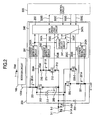
- Current regeneration diodes 2-1 and 2-2 are provided between the downstream side of the injectors 3-1 and 3-2 and a path on the booster voltage side.
- an anode of the current regeneration diode 2-1 is connected to a path between the injector 3-1 and first downstream side driver FET 220-1, and a cathode thereof is connected to a path between the booster side current detector resistor 201 and booster side driver FET 202.
- an anode of the current regeneration diode 2-2 is connected to a path between the injector 3-2 and second downstream side driver FET 220-2, and a cathode thereof is connected to a path between the booster side current detector resistor 201 and booster side driver FET 202.
- the second hold current period 580 starts.
- the first downstream side driver FET 220-1 is controlled to be turned on and the battery side driver FET 212 is controlled to perform on/off switching.
- the battery side driver FET 212 is controlled to be turned off, whereas when the injector current 3-1A reaches the second hold start current 541, the battery side driver FET 212 is controlled to be turned on.
- the boosted voltage 100A is used.
- the injector current 3-1A is controlled to have a value between the peak stop current 520 and peak start current 521, by using the downstream side current detector resistor 221
- the current is reduced not in a short time but gently, when the first hold current transits to the second hold current.
- the booster side driver FET 202 and battery side driver FET 212 are turned off, and the first downstream side drive FET 220-1 is made conductive.
- the injector current 3-1A is circulated via the current circulating diode 222 to control the current to reduce to the second hold start current 541, by using the detector resistor 221.
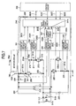
- the injector currents 3-1A and 3-2A can be detected directly during the whole current exciting period. Accordingly, as compared to the first embodiment, it is not necessary to use the detection current select circuit 247 in the injector control circuit 240 in order to switch between the current detector circuits. The circuit structure can therefore be simplified.
Landscapes
- Engineering & Computer Science (AREA)
- Chemical & Material Sciences (AREA)
- Combustion & Propulsion (AREA)
- Mechanical Engineering (AREA)
- General Engineering & Computer Science (AREA)
- Electrical Control Of Air Or Fuel Supplied To Internal-Combustion Engine (AREA)
- Fuel-Injection Apparatus (AREA)
- Dc-Dc Converters (AREA)
Applications Claiming Priority (1)
| Application Number | Priority Date | Filing Date | Title |
|---|---|---|---|
| JP2007003973A JP4474423B2 (ja) | 2007-01-12 | 2007-01-12 | 内燃機関制御装置 |
Publications (2)
| Publication Number | Publication Date |
|---|---|
| EP1944492A2 true EP1944492A2 (de) | 2008-07-16 |
| EP1944492A3 EP1944492A3 (de) | 2014-12-03 |
Family
ID=39253878
Family Applications (1)
| Application Number | Title | Priority Date | Filing Date |
|---|---|---|---|
| EP07024811.7A Withdrawn EP1944492A3 (de) | 2007-01-12 | 2007-12-20 | Verbrennungsmotorsteuerung |
Country Status (4)
| Country | Link |
|---|---|
| US (1) | US7578284B2 (de) |
| EP (1) | EP1944492A3 (de) |
| JP (1) | JP4474423B2 (de) |
| CN (1) | CN101230808B (de) |
Cited By (3)
| Publication number | Priority date | Publication date | Assignee | Title |
|---|---|---|---|---|
| WO2010079059A1 (de) * | 2009-01-07 | 2010-07-15 | Continental Automotive Gmbh | Steuern des stromflusses durch einen spulenantrieb eines ventils unter verwendung eines stromintegrals |
| US20110222202A1 (en) * | 2010-03-09 | 2011-09-15 | Hitachi Automotive Systems, Ltd. | Electromagnetic Valve Driving Circuit |
| EP2492478A1 (de) * | 2011-02-02 | 2012-08-29 | Hitachi Automotive Systems, Ltd. | Injektoransteuerschaltung |
Families Citing this family (32)
| Publication number | Priority date | Publication date | Assignee | Title |
|---|---|---|---|---|
| JP5055050B2 (ja) * | 2006-10-10 | 2012-10-24 | 日立オートモティブシステムズ株式会社 | 内燃機関制御装置 |
| JP4533404B2 (ja) * | 2007-05-24 | 2010-09-01 | 日立オートモティブシステムズ株式会社 | エンジン制御装置 |
| DE102007045513B4 (de) * | 2007-09-24 | 2015-03-19 | Continental Automotive Gmbh | Verfahren und Vorrichtung zum Zumessen eines Fluids |
| JP5053868B2 (ja) * | 2008-01-07 | 2012-10-24 | 日立オートモティブシステムズ株式会社 | 燃料噴射制御装置 |
| JP4815502B2 (ja) * | 2009-03-26 | 2011-11-16 | 日立オートモティブシステムズ株式会社 | 内燃機関の制御装置 |
| JP5300787B2 (ja) * | 2010-05-31 | 2013-09-25 | 日立オートモティブシステムズ株式会社 | 内燃機関制御装置 |
| JP5698938B2 (ja) | 2010-08-31 | 2015-04-08 | 日立オートモティブシステムズ株式会社 | 燃料噴射装置の駆動装置及び燃料噴射システム |
| JP5492806B2 (ja) * | 2011-02-25 | 2014-05-14 | 日立オートモティブシステムズ株式会社 | 電磁式燃料噴射弁の駆動装置 |
| JP5829131B2 (ja) * | 2012-01-11 | 2015-12-09 | 日立オートモティブシステムズ株式会社 | 燃料噴射弁の駆動制御装置 |
| US20130192566A1 (en) * | 2012-01-27 | 2013-08-01 | Bahman Gozloo | Control system having configurable auxiliary power module |
| JP6022909B2 (ja) * | 2012-11-29 | 2016-11-09 | 日立オートモティブシステムズ株式会社 | 電磁負荷制御装置 |
| JP5994756B2 (ja) * | 2013-09-13 | 2016-09-21 | 株式会社デンソー | インジェクタ駆動装置 |
| JP6105456B2 (ja) | 2013-11-29 | 2017-03-29 | 株式会社デンソー | 電磁弁駆動装置 |
| KR101567165B1 (ko) * | 2013-12-19 | 2015-11-09 | 현대자동차주식회사 | 인젝터 드라이버 |
| RU2563038C2 (ru) * | 2013-12-30 | 2015-09-20 | Российская Федерация, От Имени Которой Выступает Министерство Промышленности И Торговли Российской Федерации | Устройство управления инжектором |
| JP5865409B2 (ja) * | 2014-02-28 | 2016-02-17 | 日立オートモティブシステムズ株式会社 | 電磁式燃料噴射弁の駆動装置 |
| US10267253B2 (en) * | 2014-05-13 | 2019-04-23 | Hitachi Automotive Systems, Ltd. | Fuel injection system for internal combustion engine |
| CN106416033B (zh) | 2014-05-23 | 2019-06-04 | 日立汽车系统株式会社 | 电子控制装置 |
| JP6393346B2 (ja) * | 2015-02-05 | 2018-09-19 | 日立オートモティブシステムズ株式会社 | 内燃機関の制御装置 |
| CN104747333B (zh) * | 2015-03-11 | 2017-03-08 | 中国重汽集团济南动力有限公司 | 一种高压共轨喷油器的集成式驱动电路 |
| FR3038053B1 (fr) * | 2015-06-26 | 2019-04-05 | Continental Automotive France | Dispositif de mesure de temperature |
| JP6446340B2 (ja) * | 2015-08-24 | 2018-12-26 | 本田技研工業株式会社 | 電磁デバイス駆動装置及び車両 |
| JP6187663B2 (ja) * | 2016-10-03 | 2017-08-30 | 株式会社デンソー | 燃料噴射制御装置および燃料噴射システム |
| CN108506107B (zh) * | 2017-02-28 | 2020-08-11 | 日立汽车系统(苏州)有限公司 | 喷油控制系统及喷油控制方法 |
| JP6764534B2 (ja) * | 2017-06-30 | 2020-09-30 | 日立オートモティブシステムズ株式会社 | 電子制御装置 |
| JP6394763B2 (ja) * | 2017-08-01 | 2018-09-26 | 株式会社デンソー | 燃料噴射制御装置および燃料噴射システム |
| JP7067233B2 (ja) * | 2018-04-20 | 2022-05-16 | 株式会社デンソー | 噴射制御装置 |
| US10900391B2 (en) * | 2018-06-13 | 2021-01-26 | Vitesco Technologies USA, LLC. | Engine control system and method for controlling activation of solenoid valves |
| US20200025122A1 (en) * | 2018-07-17 | 2020-01-23 | Continental Automotive Systems, Inc. | Engine control system and method for controlling activation of solenoid valves |
| CN109469554B (zh) * | 2018-09-01 | 2022-01-14 | 哈尔滨工程大学 | 一种多模式燃料喷射执行器驱动电路 |
| FR3094408B1 (fr) * | 2019-03-26 | 2021-03-05 | Continental Automotive | Procédé de commande d’un injecteur de carburant haute pression |
| CN119467114B (zh) * | 2024-11-19 | 2025-10-31 | 浙江吉利控股集团有限公司 | 一种双燃料喷嘴的切换电路及车辆 |
Citations (1)
| Publication number | Priority date | Publication date | Assignee | Title |
|---|---|---|---|---|
| JP2003106200A (ja) | 2001-09-28 | 2003-04-09 | Hitachi Ltd | 燃料噴射装置を備えた内燃機関の制御装置 |
Family Cites Families (10)
| Publication number | Priority date | Publication date | Assignee | Title |
|---|---|---|---|---|
| DE3402759A1 (de) * | 1984-01-27 | 1985-08-01 | Robert Bosch Gmbh, 7000 Stuttgart | Stromregler fuer elektromagnetische stellantriebe |
| US5381297A (en) * | 1993-06-18 | 1995-01-10 | Siemens Automotive L.P. | System and method for operating high speed solenoid actuated devices |
| US5717562A (en) * | 1996-10-15 | 1998-02-10 | Caterpillar Inc. | Solenoid injector driver circuit |
| US5752482A (en) * | 1997-03-28 | 1998-05-19 | Cummins Engine Company, Inc. | System for integrally controlling current flow through number of inductive loads |
| US5975058A (en) * | 1998-10-13 | 1999-11-02 | Outboard Marine Corporation | Start-assist circuit |
| JP4103254B2 (ja) | 1999-06-29 | 2008-06-18 | 株式会社デンソー | 電磁負荷の駆動装置 |
| US6407593B1 (en) * | 1999-06-30 | 2002-06-18 | Denso Corporation | Electromagnetic load control apparatus having variable drive-starting energy supply |
| JP3825235B2 (ja) | 2000-08-22 | 2006-09-27 | 株式会社日立製作所 | インジェクタ駆動回路 |
| US7057870B2 (en) * | 2003-07-17 | 2006-06-06 | Cummins, Inc. | Inductive load driver circuit and system |
| JP4251201B2 (ja) * | 2006-07-20 | 2009-04-08 | トヨタ自動車株式会社 | インジェクタ駆動装置 |
-
2007
- 2007-01-12 JP JP2007003973A patent/JP4474423B2/ja active Active
- 2007-12-17 US US11/958,096 patent/US7578284B2/en active Active
- 2007-12-20 EP EP07024811.7A patent/EP1944492A3/de not_active Withdrawn
-
2008
- 2008-01-14 CN CN200810002651.9A patent/CN101230808B/zh active Active
Patent Citations (1)
| Publication number | Priority date | Publication date | Assignee | Title |
|---|---|---|---|---|
| JP2003106200A (ja) | 2001-09-28 | 2003-04-09 | Hitachi Ltd | 燃料噴射装置を備えた内燃機関の制御装置 |
Cited By (6)
| Publication number | Priority date | Publication date | Assignee | Title |
|---|---|---|---|---|
| WO2010079059A1 (de) * | 2009-01-07 | 2010-07-15 | Continental Automotive Gmbh | Steuern des stromflusses durch einen spulenantrieb eines ventils unter verwendung eines stromintegrals |
| US20110222202A1 (en) * | 2010-03-09 | 2011-09-15 | Hitachi Automotive Systems, Ltd. | Electromagnetic Valve Driving Circuit |
| EP2365202A3 (de) * | 2010-03-09 | 2012-09-05 | Hitachi Automotive Systems, Ltd. | Elektromagnetische Ventilsteuerschaltung |
| US8599530B2 (en) | 2010-03-09 | 2013-12-03 | Hitachi Automotive Systems, Ltd. | Electromagnetic valve driving circuit |
| EP2492478A1 (de) * | 2011-02-02 | 2012-08-29 | Hitachi Automotive Systems, Ltd. | Injektoransteuerschaltung |
| US8649151B2 (en) | 2011-02-02 | 2014-02-11 | Hitachi Automotive Systems, Ltd. | Injector drive circuit |
Also Published As
| Publication number | Publication date |
|---|---|
| EP1944492A3 (de) | 2014-12-03 |
| CN101230808B (zh) | 2011-07-13 |
| JP4474423B2 (ja) | 2010-06-02 |
| US7578284B2 (en) | 2009-08-25 |
| JP2008169762A (ja) | 2008-07-24 |
| US20080289607A1 (en) | 2008-11-27 |
| CN101230808A (zh) | 2008-07-30 |
Similar Documents
| Publication | Publication Date | Title |
|---|---|---|
| EP1944492A2 (de) | Verbrennungsmotorsteuerung | |
| US7621259B2 (en) | Internal combustion engine controller | |
| JP5470294B2 (ja) | インジェクタ駆動回路 | |
| CN101418738B (zh) | 内燃机控制装置 | |
| EP2365202B1 (de) | Elektromagnetische Ventilsteuerschaltung | |
| US8081498B2 (en) | Internal combustion engine controller | |
| US7057870B2 (en) | Inductive load driver circuit and system | |
| CN104018948B (zh) | 内燃机控制装置 | |
| JP5345230B2 (ja) | 内燃機関制御装置 | |
| JP4876174B2 (ja) | 内燃機関制御装置 | |
| JP6633093B2 (ja) | 車両用制御装置 | |
| JP7135809B2 (ja) | 噴射制御装置 | |
| JP3825235B2 (ja) | インジェクタ駆動回路 | |
| JP4635352B2 (ja) | ピエゾアクチュエータ駆動回路および燃料噴射装置 | |
| JP6418124B2 (ja) | 燃料噴射制御装置 | |
| JP2014105685A (ja) | 電磁負荷制御装置 |
Legal Events
| Date | Code | Title | Description |
|---|---|---|---|
| PUAI | Public reference made under article 153(3) epc to a published international application that has entered the european phase |
Free format text: ORIGINAL CODE: 0009012 |
|
| AK | Designated contracting states |
Kind code of ref document: A2 Designated state(s): AT BE BG CH CY CZ DE DK EE ES FI FR GB GR HU IE IS IT LI LT LU LV MC MT NL PL PT RO SE SI SK TR |
|
| AX | Request for extension of the european patent |
Extension state: AL BA HR MK RS |
|
| 17P | Request for examination filed |
Effective date: 20090623 |
|
| PUAL | Search report despatched |
Free format text: ORIGINAL CODE: 0009013 |
|
| AK | Designated contracting states |
Kind code of ref document: A3 Designated state(s): AT BE BG CH CY CZ DE DK EE ES FI FR GB GR HU IE IS IT LI LT LU LV MC MT NL PL PT RO SE SI SK TR |
|
| AX | Request for extension of the european patent |
Extension state: AL BA HR MK RS |
|
| RIC1 | Information provided on ipc code assigned before grant |
Ipc: F02D 41/20 20060101AFI20141024BHEP Ipc: F02D 41/22 20060101ALN20141024BHEP |
|
| AKX | Designation fees paid |
Designated state(s): DE |
|
| AXX | Extension fees paid |
Extension state: MK Extension state: HR Extension state: BA Extension state: AL Extension state: RS |
|
| STAA | Information on the status of an ep patent application or granted ep patent |
Free format text: STATUS: THE APPLICATION IS DEEMED TO BE WITHDRAWN |
|
| 18D | Application deemed to be withdrawn |
Effective date: 20150604 |