EP1944562A1 - Conditionneur d'air - Google Patents
Conditionneur d'air Download PDFInfo
- Publication number
- EP1944562A1 EP1944562A1 EP06798039A EP06798039A EP1944562A1 EP 1944562 A1 EP1944562 A1 EP 1944562A1 EP 06798039 A EP06798039 A EP 06798039A EP 06798039 A EP06798039 A EP 06798039A EP 1944562 A1 EP1944562 A1 EP 1944562A1
- Authority
- EP
- European Patent Office
- Prior art keywords
- heat exchanger
- pressure refrigerant
- low
- refrigerant
- pressure
- Prior art date
- Legal status (The legal status is an assumption and is not a legal conclusion. Google has not performed a legal analysis and makes no representation as to the accuracy of the status listed.)
- Granted
Links
Images



Classifications
-
- F—MECHANICAL ENGINEERING; LIGHTING; HEATING; WEAPONS; BLASTING
- F25—REFRIGERATION OR COOLING; COMBINED HEATING AND REFRIGERATION SYSTEMS; HEAT PUMP SYSTEMS; MANUFACTURE OR STORAGE OF ICE; LIQUEFACTION SOLIDIFICATION OF GASES
- F25B—REFRIGERATION MACHINES, PLANTS OR SYSTEMS; COMBINED HEATING AND REFRIGERATION SYSTEMS; HEAT PUMP SYSTEMS
- F25B1/00—Compression machines, plants or systems with non-reversible cycle
-
- F—MECHANICAL ENGINEERING; LIGHTING; HEATING; WEAPONS; BLASTING
- F25—REFRIGERATION OR COOLING; COMBINED HEATING AND REFRIGERATION SYSTEMS; HEAT PUMP SYSTEMS; MANUFACTURE OR STORAGE OF ICE; LIQUEFACTION SOLIDIFICATION OF GASES
- F25B—REFRIGERATION MACHINES, PLANTS OR SYSTEMS; COMBINED HEATING AND REFRIGERATION SYSTEMS; HEAT PUMP SYSTEMS
- F25B13/00—Compression machines, plants or systems, with reversible cycle
-
- F—MECHANICAL ENGINEERING; LIGHTING; HEATING; WEAPONS; BLASTING
- F25—REFRIGERATION OR COOLING; COMBINED HEATING AND REFRIGERATION SYSTEMS; HEAT PUMP SYSTEMS; MANUFACTURE OR STORAGE OF ICE; LIQUEFACTION SOLIDIFICATION OF GASES
- F25B—REFRIGERATION MACHINES, PLANTS OR SYSTEMS; COMBINED HEATING AND REFRIGERATION SYSTEMS; HEAT PUMP SYSTEMS
- F25B40/00—Subcoolers, desuperheaters or superheaters
-
- F—MECHANICAL ENGINEERING; LIGHTING; HEATING; WEAPONS; BLASTING
- F28—HEAT EXCHANGE IN GENERAL
- F28D—HEAT-EXCHANGE APPARATUS, NOT PROVIDED FOR IN ANOTHER SUBCLASS, IN WHICH THE HEAT-EXCHANGE MEDIA DO NOT COME INTO DIRECT CONTACT
- F28D7/00—Heat-exchange apparatus having stationary tubular conduit assemblies for both heat-exchange media, the media being in contact with different sides of a conduit wall
- F28D7/0008—Heat-exchange apparatus having stationary tubular conduit assemblies for both heat-exchange media, the media being in contact with different sides of a conduit wall the conduits for one medium being in heat conductive contact with the conduits for the other medium
- F28D7/0016—Heat-exchange apparatus having stationary tubular conduit assemblies for both heat-exchange media, the media being in contact with different sides of a conduit wall the conduits for one medium being in heat conductive contact with the conduits for the other medium the conduits for one medium or the conduits for both media being bent
-
- F—MECHANICAL ENGINEERING; LIGHTING; HEATING; WEAPONS; BLASTING
- F28—HEAT EXCHANGE IN GENERAL
- F28D—HEAT-EXCHANGE APPARATUS, NOT PROVIDED FOR IN ANOTHER SUBCLASS, IN WHICH THE HEAT-EXCHANGE MEDIA DO NOT COME INTO DIRECT CONTACT
- F28D7/00—Heat-exchange apparatus having stationary tubular conduit assemblies for both heat-exchange media, the media being in contact with different sides of a conduit wall
- F28D7/10—Heat-exchange apparatus having stationary tubular conduit assemblies for both heat-exchange media, the media being in contact with different sides of a conduit wall the conduits being arranged one within the other, e.g. concentrically
- F28D7/106—Heat-exchange apparatus having stationary tubular conduit assemblies for both heat-exchange media, the media being in contact with different sides of a conduit wall the conduits being arranged one within the other, e.g. concentrically consisting of two coaxial conduits or modules of two coaxial conduits
-
- F—MECHANICAL ENGINEERING; LIGHTING; HEATING; WEAPONS; BLASTING
- F25—REFRIGERATION OR COOLING; COMBINED HEATING AND REFRIGERATION SYSTEMS; HEAT PUMP SYSTEMS; MANUFACTURE OR STORAGE OF ICE; LIQUEFACTION SOLIDIFICATION OF GASES
- F25B—REFRIGERATION MACHINES, PLANTS OR SYSTEMS; COMBINED HEATING AND REFRIGERATION SYSTEMS; HEAT PUMP SYSTEMS
- F25B2313/00—Compression machines, plants or systems with reversible cycle not otherwise provided for
- F25B2313/027—Compression machines, plants or systems with reversible cycle not otherwise provided for characterised by the reversing means
- F25B2313/02741—Compression machines, plants or systems with reversible cycle not otherwise provided for characterised by the reversing means using one four-way valve
Definitions
- the present invention relates to an air conditioning apparatus that uses a supercooling heat exchanger.
- FIG. 4 shows a configuration of an air conditioning apparatus that uses a conventional supercooling heat exchanger.
- a compressor 1 a four-way switching valve 2, an outdoor-side heat exchanger 3 that functions as a condenser during the cooling operation and as an evaporator during the heating operation, a heating expansion valve 4, a receiver 5, a cooling expansion valve 6, an indoor-side heat exchanger 8 that functions as an evaporator during the cooling operation and as a condenser during the heating operation, and other components are connected sequentially via the four-way switching valve 2, thereby constituting a refrigerating cycle for air conditioning as is shown in the drawing.
- the switching operation of the four-way switching valve 2 allows a refrigerant to be reversibly circulated in the direction shown by solid arrows in the drawing during the cooling operation, and in the direction shown by dashed arrows in the drawing during the heating operation, thereby resulting in cooling and heating, respectively.
- the outdoor-side heat exchanger 3 and the indoor-side heat exchanger 8 are both configured to include numerous refrigerant paths. Therefore, even if the capacity of the flow divider portion to distribute the refrigerant is improved to a maximum, it is difficult to distribute the refrigerant evenly throughout the refrigerant paths.
- the amount of pressure reduction in the heating expansion valve 4 or cooling expansion valve 6 is appropriately set so that the refrigerant of the exit side of the outdoor-side heat exchanger 3 or the indoor-side heat exchanger 8 is in appropriately humidified condition.
- maximum performance as the evaporator can be guaranteed even if, for example, the refrigerant drifts into the outdoor-side heat exchanger 3 or the indoor-side heat exchanger 8, and therefore the evaporator can be made as compact as possible.
- the performance of the evaporator can be further improved by removing the refrigerant supercooling of the exit side of the condenser, increasing the difference in enthalpy of the evaporator side to reduce circulating volume, and reducing the pressure loss on the evaporator side.
- This is accomplished by providing a liquid-gas heat exchanger 13 having a double pipe structure, composed of a low-pressure refrigerant suction pipe 14 as an inner pipe and a high-pressure liquid refrigerant pipe 15 as an outer pipe, as a supercooling heat exchanger.
- liquid-gas heat exchanger 13 e.g., the flow rate of the refrigerant, the length of the double pipes, the inside diameter of the outer pipe, and the outside diameter of the inner pipe are set in a predetermined manner appropriately.
- the liquid-gas heat exchanger 13 As the liquid-gas heat exchanger 13 is provided in this manner, the refrigerant of the exit side of the evaporator is superheated, backflow into the compressor 1 can be prevented, the refrigerant of the exit side of the condenser is supercooled, and the difference in enthalpy of the evaporator side can be increased to reduce circulating volume. Therefore, the pressure loss can also be reduced, and the evaporator 8 (or the evaporator 3) can be made even more compact (see Patent Document 1 as an example).
- a supercooling heat exchanger in which heat is exchanged between a high-pressure refrigerant and a low-pressure refrigerant as described above has problems in that since the refrigerant flows in opposite directions during cooling and heating, the flows are parallel in either of the operating modes, and heat exchange is less efficient. For example, in the case shown in FIG. 4 , the flows are countercurrent to each other during cooling and are parallel to each other during heating, causing heat exchange to be less efficient.
- the present invention was designed in order to resolve such problems, and an object thereof is to provide an air conditioning apparatus comprising a supercooling heat exchanger for exchanging heat between a low-pressure refrigerant and a high-pressure refrigerant, wherein the supercooling heat exchanger is divided into a first heat exchanger and a second heat exchanger, either one of these heat exchangers is disposed so that the high-pressure refrigerant and the low-pressure refrigerant flow countercurrent to each other, and the other heat exchanger is disposed so that the high-pressure refrigerant and the low-pressure refrigerant flow parallel to each other, whereby the above-described problems with conventional practice are appropriately resolved.
- the present invention is configured with the following means of solving these problems.
- the means for solving the problems in accordance with this aspect is an air conditioning apparatus comprising a supercooling heat exchanger 13 for exchanging heat between a low-pressure refrigerant and a high-pressure refrigerant, characterized in that: the supercooling heat exchanger 13 is divided into two first and second heat exchangers 13A, 13B; either the first heat exchanger 13A or the second heat exchanger 13B is disposed so that the high-pressure refrigerant and the low-pressure refrigerant flow countercurrent to each other; and the other heat exchanger, i.e., either the second heat exchanger 13B or the first heat exchanger 13A, is disposed so that the high-pressure refrigerant and the low-pressure refrigerant flow parallel to each other.
- the supercooling heat exchanger 13 for exchanging heat between a high-pressure refrigerant and a low-pressure refrigerant as previously described has problems in that since the refrigerants flow in opposite directions during cooling and heating, the flows are parallel in either of the operating modes, and heat exchange is less efficient.
- the supercooling heat exchanger 13 is divided into two heat exchangers, i.e., the first heat exchanger 13A and the second heat exchanger 13B, either the first heat exchanger 13A or the second heat exchanger 13B is disposed so that the high-pressure refrigerant and the low-pressure refrigerant flow countercurrent to each other, and the other heat exchanger, i.e., either the second heat exchanger 13B or the first heat exchanger 13A is disposed so that the high-pressure refrigerant and the low-pressure refrigerant flow parallel to each other, whereby the supercooling heat exchanger 13 can maintain its heat exchange performance without variation even if the direction of refrigerant flow changes during cooling or heating.
- the means for solving the problems in accordance with this aspect is characterized in that, in the configuration of the means for solving the problems in accordance with the invention of the first aspect, the first and second heat exchangers 13A, 13B are both configured by winding a high-pressure liquid refrigerant pipe 15 around the external periphery of a low-pressure refrigerant suction pipe 14.
- first and second heat exchangers 13A, 13B are both configured by winding the high-pressure liquid refrigerant pipe 15 around the low-pressure refrigerant suction pipe 14, the capacity of the heat exchanger itself does not need to be increased, and the supercooling heat exchangers 13A, 13B can be made as small as possible.
- the means for solving the problems in accordance with this aspect is characterized in that, in the configuration of the means for solving the problems in accordance with the invention of the first aspect, the first and second heat exchangers 13A, 13B are both configured by fitting a high-pressure liquid refrigerant pipe 15 around the external periphery of a low-pressure refrigerant suction pipe 14 in a coaxial structure, wherein the high-pressure liquid refrigerant pipe 15 is larger in diameter than the low-pressure refrigerant suction pipe 14.
- first and second supercooling heat exchangers 13A, 13B both have a double-pipe structure in which the high-pressure liquid refrigerant pipe 15 is fitted coaxially over the low-pressure refrigerant suction pipe 14, the structures of the supercooling heat exchangers 13A, 13B themselves are simplified.
- the supercooling heat exchanger can maintain high heat exchange performance even when the flows of the refrigerants change direction during cooling and heating.
- the evaporator can be made more compact.
- the supercooling heat exchanger itself can be made as small as possible.
- FIGS. 1 and 2 of the attached drawings show the configuration of the entirety and relevant parts of the refrigerant circuits in an air conditioning apparatus according to a preferred embodiment of the present invention.
- a compressor 1, a four-way switching valve 2, an outdoor-side heat exchanger 3 that functions as a condenser during the cooling operation and as an evaporator during the heating operation, a heating expansion valve 4, a receiver 5, a cooling expansion valve 6, an indoor-side heat exchanger 8 that functions as an evaporator during the cooling operation and as a condenser during the heating operation, and other components are connected sequentially via the four-way switching valve 2, thereby constituting a refrigerating cycle for air conditioning as shown in the drawing.
- the switching operation of the four-way switching valve 2 allows refrigerant to be reversibly circulated in the direction shown by solid arrows in the diagram during the cooling operation, and in the direction shown by dashed arrows in the diagram during the heating operation, thereby resulting in cooling and heating, respectively.
- a liquid-gas heat exchanger 13 is provided in this embodiment as well as the case in FIG. 4 described previously.
- This liquid-gas heat exchanger 13 comprises a low-pressure refrigerant suction pipe 14 and a high-pressure liquid refrigerant pipe 15, and is used as a supercooling heat exchanger for exchanging heat between low-pressure refrigerant and high-pressure refrigerant.
- liquid-gas heat exchanger 13 As the liquid-gas heat exchanger 13 is provided in this manner, refrigerant of the exit side of the evaporator is superheated, backflow into the compressor 1 can be prevented, the refrigerant of the exit side of the condenser is supercooled, and the difference in enthalpy of the evaporator side can be increased to reduce refrigerant circulating volume, as was described previously. Therefore, pressure loss can also be reduced, and the evaporator (the indoor-side heat exchanger 8 during cooling or the outdoor-side heat exchanger 3 during heating) can be made as compact as possible.
- the liquid-gas heat exchanger 13 is divided into two liquid-gas heat exchangers, i.e., a first liquid-gas heat exchanger 13A and a second liquid-gas heat exchanger 13B in which refrigerants flow in mutually opposite directions.
- the first heat exchanger 13A may, for example, be disposed so that the high-pressure refrigerant and low-pressure refrigerant flow countercurrent to each other, and the second heat exchanger 13B may be disposed so that the high-pressure refrigerant and low-pressure refrigerant flow parallel to each other.
- the liquid-gas heat exchanger 13 can maintain its performance without variation as shown in the diagrams, even when the refrigerant flow changes direction during cooling and heating.
- the refrigerant of the exit side of the condenser is supercooled without variation during heating, and the difference in enthalpy of the evaporator side can be increased to reduce the circulating volume.
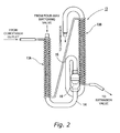
- first and second liquid-gas heat exchangers 13A, 13B are both configured so that the high-pressure liquid refrigerant pipe 15 from the exit side of the condenser that is smaller in diameter than the low-pressure refrigerant suction pipe 14 is wound in a helical structure in mutually opposite directions, for example, as shown in detail in FIG. 2 , around the external periphery of the low-pressure refrigerant suction pipe 14.
- the existing low-pressure refrigerant suction pipe 14 leads from the indoor-side heat exchanger (evaporator) 8 during cooling or from the outdoor-side heat exchanger (evaporator) 3 during heating back to the refrigerant suction inlet in the compressor 1 via the four-way switching valve 2. Therefore, the supercooling heat exchanger 13 itself can have a small capacity and can be made as small in size as possible.
- the improvement in supercooling heat exchange efficiency is effective in contributing to making the evaporators themselves smaller and more compact.
- winding the high-pressure liquid refrigerant pipe 15 around the existing low-pressure refrigerant suction pipe 14 as shown in FIG. 2 makes it possible to inhibit increases in suctioned gas pressure loss, and to prevent the COP from decreasing.
- the reference numeral 16 in FIG. 2 denotes a muffler for gas refrigerant in the low-pressure refrigerant suction pipe 14.
- the divided first and second heat exchangers 13A, 13B have a structure in which a high-pressure liquid refrigerant pipe 15 having a small diameter is helically wound around an existing low-pressure refrigerant suction pipe 14 that goes from the four-way switching valve 2 to the refrigerant suction inlet of the compressor 1, as shown in FIG. 2 .
- a high-pressure liquid refrigerant pipe 15 having a small diameter is helically wound around an existing low-pressure refrigerant suction pipe 14 that goes from the four-way switching valve 2 to the refrigerant suction inlet of the compressor 1, as shown in FIG. 2 .
- FIG. 1 In another possible configuration, as shown in FIG.
- the first and second heat exchangers 13A, 13B have a double-pipe structure in which a high-pressure liquid refrigerant pipe 15 larger in diameter than the low-pressure refrigerant suction pipe 14 is fitted as a coaxial structure around the external periphery of the low-pressure refrigerant suction pipe 14, and these pipes are disposed so that the refrigerant flows in mutually opposite directions.
- first and second heat exchangers 13A, 13B for supercooling have a double-pipe structure in which the high-pressure liquid refrigerant pipe 15 is fitted as a coaxial structure around the low-pressure refrigerant suction pipe 14, the structure of the supercooling heat exchanger itself is simplified.
- the present invention can be widely utilized within the field of air conditioning apparatuses that use supercooling heat exchangers.
Landscapes
- Engineering & Computer Science (AREA)
- Physics & Mathematics (AREA)
- Thermal Sciences (AREA)
- Mechanical Engineering (AREA)
- General Engineering & Computer Science (AREA)
- Compression-Type Refrigeration Machines With Reversible Cycles (AREA)
- Heat-Exchange Devices With Radiators And Conduit Assemblies (AREA)
Applications Claiming Priority (2)
| Application Number | Priority Date | Filing Date | Title |
|---|---|---|---|
| JP2005275493A JP3982545B2 (ja) | 2005-09-22 | 2005-09-22 | 空気調和装置 |
| PCT/JP2006/318376 WO2007034745A1 (fr) | 2005-09-22 | 2006-09-15 | Conditionneur d'air |
Publications (3)
| Publication Number | Publication Date |
|---|---|
| EP1944562A1 true EP1944562A1 (fr) | 2008-07-16 |
| EP1944562A4 EP1944562A4 (fr) | 2011-03-23 |
| EP1944562B1 EP1944562B1 (fr) | 2013-04-17 |
Family
ID=37888790
Family Applications (1)
| Application Number | Title | Priority Date | Filing Date |
|---|---|---|---|
| EP06798039.1A Not-in-force EP1944562B1 (fr) | 2005-09-22 | 2006-09-15 | Conditionneur d'air |
Country Status (7)
| Country | Link |
|---|---|
| US (1) | US20090282861A1 (fr) |
| EP (1) | EP1944562B1 (fr) |
| JP (1) | JP3982545B2 (fr) |
| KR (1) | KR100905995B1 (fr) |
| CN (1) | CN101268312B (fr) |
| AU (1) | AU2006293191B2 (fr) |
| WO (1) | WO2007034745A1 (fr) |
Cited By (2)
| Publication number | Priority date | Publication date | Assignee | Title |
|---|---|---|---|---|
| CN102692100A (zh) * | 2011-03-25 | 2012-09-26 | 株式会社电装 | 热交换系统和车辆制冷循环系统 |
| EP3722729A4 (fr) * | 2017-12-06 | 2020-11-11 | Mitsubishi Electric Corporation | Échangeur de chaleur, dispositif à cycle frigorifique, et procédé de fabrication d'échangeur de chaleur |
Families Citing this family (31)
| Publication number | Priority date | Publication date | Assignee | Title |
|---|---|---|---|---|
| JP2008304078A (ja) * | 2007-06-05 | 2008-12-18 | Denso Corp | 冷凍サイクル装置 |
| JP5473922B2 (ja) * | 2007-10-09 | 2014-04-16 | ビーイー・エアロスペース・インコーポレーテッド | 熱制御システム |
| JP2009115415A (ja) * | 2007-11-08 | 2009-05-28 | Calsonic Kansei Corp | 超臨界冷凍サイクル |
| JP4947043B2 (ja) * | 2008-07-14 | 2012-06-06 | ダイキン工業株式会社 | 空気調和装置の室外機およびその製造方法 |
| DK176868B1 (da) * | 2008-09-16 | 2010-02-01 | Lars Christian Wulf Zimmermann | Symmetrisk kølemiddelregulator for oversvømmet multikanalfordamper |
| ATE554643T1 (de) * | 2009-08-05 | 2012-05-15 | Abb Research Ltd | Verdampfer und kühlkreis |
| US9593872B2 (en) | 2009-10-27 | 2017-03-14 | Mitsubishi Electric Corporation | Heat pump |
| CN103154639B (zh) * | 2010-10-12 | 2015-04-01 | 三菱电机株式会社 | 空调装置 |
| JP2012097957A (ja) * | 2010-11-02 | 2012-05-24 | Showa Denko Kk | 中間熱交換器 |
| CN102095271A (zh) * | 2011-03-01 | 2011-06-15 | 四川长虹空调有限公司 | 热泵空调器 |
| JP5938821B2 (ja) * | 2011-12-12 | 2016-06-22 | E・T・E株式会社 | 冷凍装置 |
| US9482445B2 (en) * | 2012-09-06 | 2016-11-01 | Jiangsu Tenesun Electrical Appliance Co., Ltd. | Heat pump water heater with heat utilization balance processor and heat utilization balance processor thereof |
| CN103807936B (zh) * | 2012-11-08 | 2018-06-26 | 杭州三花研究院有限公司 | 一种热泵空调系统 |
| WO2014200476A1 (fr) * | 2013-06-12 | 2014-12-18 | Danfoss Turbocor Compressors B.V. | Compresseur doté d'un passage de refroidissement de rotor |
| JP2015034671A (ja) * | 2013-08-09 | 2015-02-19 | 株式会社アタゴ製作所 | ヒートポンプ式給湯機の熱交換器 |
| EP3683232A1 (fr) | 2013-09-13 | 2020-07-22 | F. Hoffmann-La Roche AG | Procédés et compositions comprenant des polypeptides recombinants purifiés |
| CN105928241B (zh) * | 2016-06-01 | 2018-07-17 | 唐玉敏 | 一种换热系统多级混联置换模块 |
| CN105928240B (zh) * | 2016-06-01 | 2019-04-12 | 唐玉敏 | 一种换热系统 |
| CN105928267B (zh) * | 2016-06-01 | 2018-10-30 | 唐玉敏 | 一种多级并联置换换热系统 |
| CN105928398A (zh) * | 2016-06-01 | 2016-09-07 | 唐玉敏 | 一种换热系统多级并联置换模块 |
| CN106016860B (zh) * | 2016-06-01 | 2018-10-09 | 唐玉敏 | 一种换热系统置换模块 |
| CN105928242B (zh) * | 2016-06-01 | 2018-07-20 | 唐玉敏 | 一种换热系统多级串联置换模块 |
| CN105928231B (zh) * | 2016-06-01 | 2018-10-09 | 唐玉敏 | 一种多级串联置换换热系统 |
| CN105928397B (zh) * | 2016-06-01 | 2018-03-20 | 唐玉敏 | 一种多级混联置换换热系统 |
| SE542346C2 (en) | 2017-05-22 | 2020-04-14 | Swep Int Ab | Reversible refrigeration system |
| SE546940C2 (en) * | 2017-05-22 | 2025-03-11 | Swep Int Ab | A reversible refrigeration system |
| SE544732C2 (en) * | 2017-05-22 | 2022-10-25 | Swep Int Ab | A reversible refrigeration system |
| KR20190055614A (ko) * | 2017-11-15 | 2019-05-23 | 엘지전자 주식회사 | 판형 열교환기 및 이를 포함하는 공기 조화기 |
| CN108302839A (zh) * | 2017-12-29 | 2018-07-20 | 青岛海尔空调器有限总公司 | 空调器系统 |
| WO2020202553A1 (fr) * | 2019-04-05 | 2020-10-08 | 三菱電機株式会社 | Appareil à cycle frigorifique |
| US12215897B2 (en) | 2019-07-22 | 2025-02-04 | Mitsubishi Electric Corporation | Air conditioning apparatus and outdoor unit |
Family Cites Families (10)
| Publication number | Priority date | Publication date | Assignee | Title |
|---|---|---|---|---|
| JPS58135667U (ja) * | 1982-03-08 | 1983-09-12 | 松下冷機株式会社 | 冷凍サイクル |
| DE3505789A1 (de) * | 1985-02-20 | 1986-08-21 | Grote, Paul, 2901 Friedrichsfehn | Spiralwaermetauscher |
| JP3336628B2 (ja) | 1992-05-29 | 2002-10-21 | ダイキン工業株式会社 | 冷凍装置 |
| JPH06213518A (ja) * | 1993-01-13 | 1994-08-02 | Hitachi Ltd | 混合冷媒用ヒートポンプ式エアコン |
| JPH1054616A (ja) * | 1996-08-14 | 1998-02-24 | Daikin Ind Ltd | 空気調和機 |
| TW568254U (en) * | 1997-01-06 | 2003-12-21 | Mitsubishi Electric Corp | Refrigerant circulating apparatus |
| JPH11325655A (ja) * | 1998-05-14 | 1999-11-26 | Matsushita Seiko Co Ltd | 消音器および空気調和機 |
| JP2001056188A (ja) * | 1999-06-10 | 2001-02-27 | Sanden Corp | 蒸気圧縮式冷凍サイクル等に使用される熱交換器 |
| JP4120221B2 (ja) * | 2000-04-28 | 2008-07-16 | ダイキン工業株式会社 | 冷媒及び油回収運転方法、および、冷媒及び油の回収制御装置 |
| JP3811116B2 (ja) * | 2001-10-19 | 2006-08-16 | 松下電器産業株式会社 | 冷凍サイクル装置 |
-
2005
- 2005-09-22 JP JP2005275493A patent/JP3982545B2/ja not_active Expired - Fee Related
-
2006
- 2006-09-15 EP EP06798039.1A patent/EP1944562B1/fr not_active Not-in-force
- 2006-09-15 US US12/067,087 patent/US20090282861A1/en not_active Abandoned
- 2006-09-15 AU AU2006293191A patent/AU2006293191B2/en not_active Ceased
- 2006-09-15 CN CN2006800342799A patent/CN101268312B/zh not_active Expired - Fee Related
- 2006-09-15 WO PCT/JP2006/318376 patent/WO2007034745A1/fr not_active Ceased
-
2008
- 2008-04-04 KR KR1020087008289A patent/KR100905995B1/ko not_active Expired - Fee Related
Cited By (2)
| Publication number | Priority date | Publication date | Assignee | Title |
|---|---|---|---|---|
| CN102692100A (zh) * | 2011-03-25 | 2012-09-26 | 株式会社电装 | 热交换系统和车辆制冷循环系统 |
| EP3722729A4 (fr) * | 2017-12-06 | 2020-11-11 | Mitsubishi Electric Corporation | Échangeur de chaleur, dispositif à cycle frigorifique, et procédé de fabrication d'échangeur de chaleur |
Also Published As
| Publication number | Publication date |
|---|---|
| AU2006293191A1 (en) | 2007-03-29 |
| KR100905995B1 (ko) | 2009-07-06 |
| CN101268312B (zh) | 2010-05-19 |
| CN101268312A (zh) | 2008-09-17 |
| AU2006293191B2 (en) | 2009-11-19 |
| EP1944562A4 (fr) | 2011-03-23 |
| JP3982545B2 (ja) | 2007-09-26 |
| WO2007034745A1 (fr) | 2007-03-29 |
| KR20080042178A (ko) | 2008-05-14 |
| JP2007085647A (ja) | 2007-04-05 |
| EP1944562B1 (fr) | 2013-04-17 |
| US20090282861A1 (en) | 2009-11-19 |
Similar Documents
| Publication | Publication Date | Title |
|---|---|---|
| EP1944562B1 (fr) | Conditionneur d'air | |
| JP5332604B2 (ja) | 冷暖同時運転型空気調和装置 | |
| EP2339269B1 (fr) | Climatiseur | |
| EP3217115B1 (fr) | Appareil de climatisation | |
| US20010037649A1 (en) | Air conditioner using flammable refrigerant | |
| EP3680565B1 (fr) | Dispositif de climatisation | |
| WO2009131083A1 (fr) | Dispositif de réfrigération | |
| US8020405B2 (en) | Air conditioning apparatus | |
| JP2009204244A (ja) | 冷凍装置 | |
| JP2007240025A (ja) | 冷凍装置 | |
| EP1645818A2 (fr) | Climatiseur avec un circuit de réfrigérant double | |
| WO2013146415A1 (fr) | Dispositif de chauffage du type pompe à chaleur | |
| JP2009228972A (ja) | 冷凍装置 | |
| JP2008267653A (ja) | 冷凍装置 | |
| JP6984048B2 (ja) | 空気調和機 | |
| WO2017010007A1 (fr) | Climatiseur | |
| JP2007093167A (ja) | 空気調和機用液ガス熱交換器 | |
| JPH09280680A (ja) | 冷媒回路 |
Legal Events
| Date | Code | Title | Description |
|---|---|---|---|
| PUAI | Public reference made under article 153(3) epc to a published international application that has entered the european phase |
Free format text: ORIGINAL CODE: 0009012 |
|
| 17P | Request for examination filed |
Effective date: 20080417 |
|
| AK | Designated contracting states |
Kind code of ref document: A1 Designated state(s): AT BE BG CH CY CZ DE DK EE ES FI FR GB GR HU IE IS IT LI LT LU LV MC NL PL PT RO SE SI SK TR |
|
| A4 | Supplementary search report drawn up and despatched |
Effective date: 20110217 |
|
| DAX | Request for extension of the european patent (deleted) | ||
| REG | Reference to a national code |
Ref country code: DE Ref legal event code: R079 Ref document number: 602006035745 Country of ref document: DE Free format text: PREVIOUS MAIN CLASS: F25B0001000000 Ipc: F25B0013000000 |
|
| GRAP | Despatch of communication of intention to grant a patent |
Free format text: ORIGINAL CODE: EPIDOSNIGR1 |
|
| RIC1 | Information provided on ipc code assigned before grant |
Ipc: F28D 7/10 20060101ALI20121026BHEP Ipc: F25B 13/00 20060101AFI20121026BHEP Ipc: F25B 40/00 20060101ALI20121026BHEP Ipc: F28D 7/00 20060101ALI20121026BHEP |
|
| GRAS | Grant fee paid |
Free format text: ORIGINAL CODE: EPIDOSNIGR3 |
|
| GRAA | (expected) grant |
Free format text: ORIGINAL CODE: 0009210 |
|
| AK | Designated contracting states |
Kind code of ref document: B1 Designated state(s): AT BE BG CH CY CZ DE DK EE ES FI FR GB GR HU IE IS IT LI LT LU LV MC NL PL PT RO SE SI SK TR |
|
| REG | Reference to a national code |
Ref country code: GB Ref legal event code: FG4D |
|
| RIN1 | Information on inventor provided before grant (corrected) |
Inventor name: KOJIMA, MAKOTO Inventor name: SETOGUCHI, TAKAYUKI |
|
| REG | Reference to a national code |
Ref country code: CH Ref legal event code: EP |
|
| REG | Reference to a national code |
Ref country code: IE Ref legal event code: FG4D |
|
| REG | Reference to a national code |
Ref country code: AT Ref legal event code: REF Ref document number: 607554 Country of ref document: AT Kind code of ref document: T Effective date: 20130515 |
|
| REG | Reference to a national code |
Ref country code: DE Ref legal event code: R096 Ref document number: 602006035745 Country of ref document: DE Effective date: 20130613 |
|
| REG | Reference to a national code |
Ref country code: AT Ref legal event code: MK05 Ref document number: 607554 Country of ref document: AT Kind code of ref document: T Effective date: 20130417 |
|
| REG | Reference to a national code |
Ref country code: LT Ref legal event code: MG4D |
|
| REG | Reference to a national code |
Ref country code: NL Ref legal event code: VDEP Effective date: 20130417 |
|
| PG25 | Lapsed in a contracting state [announced via postgrant information from national office to epo] |
Ref country code: PT Free format text: LAPSE BECAUSE OF FAILURE TO SUBMIT A TRANSLATION OF THE DESCRIPTION OR TO PAY THE FEE WITHIN THE PRESCRIBED TIME-LIMIT Effective date: 20130819 Ref country code: AT Free format text: LAPSE BECAUSE OF FAILURE TO SUBMIT A TRANSLATION OF THE DESCRIPTION OR TO PAY THE FEE WITHIN THE PRESCRIBED TIME-LIMIT Effective date: 20130417 Ref country code: ES Free format text: LAPSE BECAUSE OF FAILURE TO SUBMIT A TRANSLATION OF THE DESCRIPTION OR TO PAY THE FEE WITHIN THE PRESCRIBED TIME-LIMIT Effective date: 20130728 Ref country code: LT Free format text: LAPSE BECAUSE OF FAILURE TO SUBMIT A TRANSLATION OF THE DESCRIPTION OR TO PAY THE FEE WITHIN THE PRESCRIBED TIME-LIMIT Effective date: 20130417 Ref country code: SI Free format text: LAPSE BECAUSE OF FAILURE TO SUBMIT A TRANSLATION OF THE DESCRIPTION OR TO PAY THE FEE WITHIN THE PRESCRIBED TIME-LIMIT Effective date: 20130417 Ref country code: SE Free format text: LAPSE BECAUSE OF FAILURE TO SUBMIT A TRANSLATION OF THE DESCRIPTION OR TO PAY THE FEE WITHIN THE PRESCRIBED TIME-LIMIT Effective date: 20130417 Ref country code: BE Free format text: LAPSE BECAUSE OF FAILURE TO SUBMIT A TRANSLATION OF THE DESCRIPTION OR TO PAY THE FEE WITHIN THE PRESCRIBED TIME-LIMIT Effective date: 20130417 Ref country code: GR Free format text: LAPSE BECAUSE OF FAILURE TO SUBMIT A TRANSLATION OF THE DESCRIPTION OR TO PAY THE FEE WITHIN THE PRESCRIBED TIME-LIMIT Effective date: 20130718 Ref country code: IS Free format text: LAPSE BECAUSE OF FAILURE TO SUBMIT A TRANSLATION OF THE DESCRIPTION OR TO PAY THE FEE WITHIN THE PRESCRIBED TIME-LIMIT Effective date: 20130817 Ref country code: FI Free format text: LAPSE BECAUSE OF FAILURE TO SUBMIT A TRANSLATION OF THE DESCRIPTION OR TO PAY THE FEE WITHIN THE PRESCRIBED TIME-LIMIT Effective date: 20130417 |
|
| PG25 | Lapsed in a contracting state [announced via postgrant information from national office to epo] |
Ref country code: CY Free format text: LAPSE BECAUSE OF FAILURE TO SUBMIT A TRANSLATION OF THE DESCRIPTION OR TO PAY THE FEE WITHIN THE PRESCRIBED TIME-LIMIT Effective date: 20130417 Ref country code: LV Free format text: LAPSE BECAUSE OF FAILURE TO SUBMIT A TRANSLATION OF THE DESCRIPTION OR TO PAY THE FEE WITHIN THE PRESCRIBED TIME-LIMIT Effective date: 20130417 Ref country code: BG Free format text: LAPSE BECAUSE OF FAILURE TO SUBMIT A TRANSLATION OF THE DESCRIPTION OR TO PAY THE FEE WITHIN THE PRESCRIBED TIME-LIMIT Effective date: 20130717 Ref country code: PL Free format text: LAPSE BECAUSE OF FAILURE TO SUBMIT A TRANSLATION OF THE DESCRIPTION OR TO PAY THE FEE WITHIN THE PRESCRIBED TIME-LIMIT Effective date: 20130417 |
|
| PG25 | Lapsed in a contracting state [announced via postgrant information from national office to epo] |
Ref country code: SK Free format text: LAPSE BECAUSE OF FAILURE TO SUBMIT A TRANSLATION OF THE DESCRIPTION OR TO PAY THE FEE WITHIN THE PRESCRIBED TIME-LIMIT Effective date: 20130417 Ref country code: DK Free format text: LAPSE BECAUSE OF FAILURE TO SUBMIT A TRANSLATION OF THE DESCRIPTION OR TO PAY THE FEE WITHIN THE PRESCRIBED TIME-LIMIT Effective date: 20130417 Ref country code: CZ Free format text: LAPSE BECAUSE OF FAILURE TO SUBMIT A TRANSLATION OF THE DESCRIPTION OR TO PAY THE FEE WITHIN THE PRESCRIBED TIME-LIMIT Effective date: 20130417 Ref country code: EE Free format text: LAPSE BECAUSE OF FAILURE TO SUBMIT A TRANSLATION OF THE DESCRIPTION OR TO PAY THE FEE WITHIN THE PRESCRIBED TIME-LIMIT Effective date: 20130417 |
|
| PLBE | No opposition filed within time limit |
Free format text: ORIGINAL CODE: 0009261 |
|
| STAA | Information on the status of an ep patent application or granted ep patent |
Free format text: STATUS: NO OPPOSITION FILED WITHIN TIME LIMIT |
|
| PG25 | Lapsed in a contracting state [announced via postgrant information from national office to epo] |
Ref country code: NL Free format text: LAPSE BECAUSE OF FAILURE TO SUBMIT A TRANSLATION OF THE DESCRIPTION OR TO PAY THE FEE WITHIN THE PRESCRIBED TIME-LIMIT Effective date: 20130417 Ref country code: IT Free format text: LAPSE BECAUSE OF FAILURE TO SUBMIT A TRANSLATION OF THE DESCRIPTION OR TO PAY THE FEE WITHIN THE PRESCRIBED TIME-LIMIT Effective date: 20130417 Ref country code: RO Free format text: LAPSE BECAUSE OF FAILURE TO SUBMIT A TRANSLATION OF THE DESCRIPTION OR TO PAY THE FEE WITHIN THE PRESCRIBED TIME-LIMIT Effective date: 20130417 |
|
| 26N | No opposition filed |
Effective date: 20140120 |
|
| PG25 | Lapsed in a contracting state [announced via postgrant information from national office to epo] |
Ref country code: MC Free format text: LAPSE BECAUSE OF FAILURE TO SUBMIT A TRANSLATION OF THE DESCRIPTION OR TO PAY THE FEE WITHIN THE PRESCRIBED TIME-LIMIT Effective date: 20130417 |
|
| REG | Reference to a national code |
Ref country code: DE Ref legal event code: R097 Ref document number: 602006035745 Country of ref document: DE Effective date: 20140120 Ref country code: CH Ref legal event code: PL |
|
| REG | Reference to a national code |
Ref country code: IE Ref legal event code: MM4A |
|
| PG25 | Lapsed in a contracting state [announced via postgrant information from national office to epo] |
Ref country code: IE Free format text: LAPSE BECAUSE OF NON-PAYMENT OF DUE FEES Effective date: 20130915 Ref country code: CH Free format text: LAPSE BECAUSE OF NON-PAYMENT OF DUE FEES Effective date: 20130930 Ref country code: LI Free format text: LAPSE BECAUSE OF NON-PAYMENT OF DUE FEES Effective date: 20130930 |
|
| PG25 | Lapsed in a contracting state [announced via postgrant information from national office to epo] |
Ref country code: TR Free format text: LAPSE BECAUSE OF FAILURE TO SUBMIT A TRANSLATION OF THE DESCRIPTION OR TO PAY THE FEE WITHIN THE PRESCRIBED TIME-LIMIT Effective date: 20130417 |
|
| PG25 | Lapsed in a contracting state [announced via postgrant information from national office to epo] |
Ref country code: LU Free format text: LAPSE BECAUSE OF NON-PAYMENT OF DUE FEES Effective date: 20130915 Ref country code: HU Free format text: LAPSE BECAUSE OF FAILURE TO SUBMIT A TRANSLATION OF THE DESCRIPTION OR TO PAY THE FEE WITHIN THE PRESCRIBED TIME-LIMIT; INVALID AB INITIO Effective date: 20060915 |
|
| REG | Reference to a national code |
Ref country code: FR Ref legal event code: PLFP Year of fee payment: 11 |
|
| REG | Reference to a national code |
Ref country code: FR Ref legal event code: PLFP Year of fee payment: 12 |
|
| REG | Reference to a national code |
Ref country code: FR Ref legal event code: PLFP Year of fee payment: 13 |
|
| PGFP | Annual fee paid to national office [announced via postgrant information from national office to epo] |
Ref country code: GB Payment date: 20200902 Year of fee payment: 15 Ref country code: DE Payment date: 20200901 Year of fee payment: 15 Ref country code: FR Payment date: 20200812 Year of fee payment: 15 |
|
| REG | Reference to a national code |
Ref country code: DE Ref legal event code: R119 Ref document number: 602006035745 Country of ref document: DE |
|
| GBPC | Gb: european patent ceased through non-payment of renewal fee |
Effective date: 20210915 |
|
| PG25 | Lapsed in a contracting state [announced via postgrant information from national office to epo] |
Ref country code: GB Free format text: LAPSE BECAUSE OF NON-PAYMENT OF DUE FEES Effective date: 20210915 Ref country code: FR Free format text: LAPSE BECAUSE OF NON-PAYMENT OF DUE FEES Effective date: 20210930 Ref country code: DE Free format text: LAPSE BECAUSE OF NON-PAYMENT OF DUE FEES Effective date: 20220401 |