EP1949952A2 - Verfahren zur NOx-Reduktion aus Abgasen aus industriellen Prozessen - Google Patents
Verfahren zur NOx-Reduktion aus Abgasen aus industriellen Prozessen Download PDFInfo
- Publication number
- EP1949952A2 EP1949952A2 EP08153103A EP08153103A EP1949952A2 EP 1949952 A2 EP1949952 A2 EP 1949952A2 EP 08153103 A EP08153103 A EP 08153103A EP 08153103 A EP08153103 A EP 08153103A EP 1949952 A2 EP1949952 A2 EP 1949952A2
- Authority
- EP
- European Patent Office
- Prior art keywords
- exhaust gas
- nox
- range
- hnco
- temperature
- Prior art date
- Legal status (The legal status is an assumption and is not a legal conclusion. Google has not performed a legal analysis and makes no representation as to the accuracy of the status listed.)
- Withdrawn
Links
- 238000000034 method Methods 0.000 title claims abstract description 215
- 239000007789 gas Substances 0.000 title abstract description 397
- 238000004519 manufacturing process Methods 0.000 title abstract description 23
- 229930195733 hydrocarbon Natural products 0.000 claims abstract description 215
- 150000002430 hydrocarbons Chemical class 0.000 claims abstract description 208
- 239000004215 Carbon black (E152) Substances 0.000 claims abstract description 157
- 238000001321 HNCO Methods 0.000 claims abstract description 157
- OWIKHYCFFJSOEH-UHFFFAOYSA-N Isocyanic acid Chemical compound N=C=O OWIKHYCFFJSOEH-UHFFFAOYSA-N 0.000 claims abstract description 157
- 230000009467 reduction Effects 0.000 claims abstract description 114
- 238000006243 chemical reaction Methods 0.000 claims abstract description 73
- 238000010438 heat treatment Methods 0.000 claims abstract description 73
- QGZKDVFQNNGYKY-UHFFFAOYSA-N Ammonia Chemical compound N QGZKDVFQNNGYKY-UHFFFAOYSA-N 0.000 claims description 270
- 239000003638 chemical reducing agent Substances 0.000 claims description 116
- 239000000463 material Substances 0.000 claims description 45
- 239000000203 mixture Substances 0.000 claims description 44
- 230000002829 reductive effect Effects 0.000 claims description 42
- XSQUKJJJFZCRTK-UHFFFAOYSA-N Urea Chemical compound NC(N)=O XSQUKJJJFZCRTK-UHFFFAOYSA-N 0.000 claims description 38
- 239000004202 carbamide Substances 0.000 claims description 38
- 239000006227 byproduct Substances 0.000 claims description 31
- 230000003197 catalytic effect Effects 0.000 claims description 30
- ZFSLODLOARCGLH-UHFFFAOYSA-N isocyanuric acid Chemical compound OC1=NC(O)=NC(O)=N1 ZFSLODLOARCGLH-UHFFFAOYSA-N 0.000 claims description 30
- 238000005844 autocatalytic reaction Methods 0.000 claims description 22
- 239000007788 liquid Substances 0.000 claims description 22
- 239000007787 solid Substances 0.000 claims description 22
- XLYOFNOQVPJJNP-UHFFFAOYSA-N water Substances O XLYOFNOQVPJJNP-UHFFFAOYSA-N 0.000 claims description 18
- 230000000779 depleting effect Effects 0.000 claims description 17
- 239000000243 solution Substances 0.000 claims description 16
- 238000000354 decomposition reaction Methods 0.000 claims description 15
- 239000000047 product Substances 0.000 claims description 15
- -1 hydrocarbon amines Chemical class 0.000 claims description 12
- 230000002708 enhancing effect Effects 0.000 claims description 9
- 150000001875 compounds Chemical class 0.000 claims description 8
- 239000000839 emulsion Substances 0.000 claims description 8
- 239000002002 slurry Substances 0.000 claims description 8
- 238000009834 vaporization Methods 0.000 claims description 8
- 230000008016 vaporization Effects 0.000 claims description 8
- 150000001298 alcohols Chemical class 0.000 claims description 7
- 239000000155 melt Substances 0.000 claims description 5
- 150000003863 ammonium salts Chemical class 0.000 claims description 4
- 150000007524 organic acids Chemical class 0.000 claims description 4
- 235000005985 organic acids Nutrition 0.000 claims description 4
- 239000002904 solvent Substances 0.000 claims description 4
- 239000000356 contaminant Substances 0.000 abstract description 35
- 229910002089 NOx Inorganic materials 0.000 description 285
- 229910000069 nitrogen hydride Inorganic materials 0.000 description 253
- UGFAIRIUMAVXCW-UHFFFAOYSA-N Carbon monoxide Chemical compound [O+]#[C-] UGFAIRIUMAVXCW-UHFFFAOYSA-N 0.000 description 138
- 229910002091 carbon monoxide Inorganic materials 0.000 description 138
- 238000006722 reduction reaction Methods 0.000 description 109
- IJGRMHOSHXDMSA-UHFFFAOYSA-N Atomic nitrogen Chemical compound N#N IJGRMHOSHXDMSA-UHFFFAOYSA-N 0.000 description 79
- 238000002485 combustion reaction Methods 0.000 description 77
- 239000000446 fuel Substances 0.000 description 64
- MWUXSHHQAYIFBG-UHFFFAOYSA-N nitrogen oxide Inorganic materials O=[N] MWUXSHHQAYIFBG-UHFFFAOYSA-N 0.000 description 53
- 229910052757 nitrogen Inorganic materials 0.000 description 35
- 239000000376 reactant Substances 0.000 description 30
- 238000002347 injection Methods 0.000 description 29
- 239000007924 injection Substances 0.000 description 29
- 239000003054 catalyst Substances 0.000 description 28
- 230000001276 controlling effect Effects 0.000 description 28
- 230000007423 decrease Effects 0.000 description 27
- 239000002283 diesel fuel Substances 0.000 description 25
- GQPLMRYTRLFLPF-UHFFFAOYSA-N Nitrous Oxide Chemical group [O-][N+]#N GQPLMRYTRLFLPF-UHFFFAOYSA-N 0.000 description 24
- 230000000153 supplemental effect Effects 0.000 description 24
- 230000003647 oxidation Effects 0.000 description 23
- 238000007254 oxidation reaction Methods 0.000 description 23
- 238000012360 testing method Methods 0.000 description 22
- 239000000126 substance Substances 0.000 description 21
- 238000002156 mixing Methods 0.000 description 17
- 230000003247 decreasing effect Effects 0.000 description 15
- VNWKTOKETHGBQD-UHFFFAOYSA-N methane Chemical compound C VNWKTOKETHGBQD-UHFFFAOYSA-N 0.000 description 14
- 238000012986 modification Methods 0.000 description 14
- 230000004048 modification Effects 0.000 description 14
- 239000007864 aqueous solution Substances 0.000 description 13
- 230000015572 biosynthetic process Effects 0.000 description 13
- 238000011084 recovery Methods 0.000 description 13
- 239000001272 nitrous oxide Substances 0.000 description 12
- 230000001965 increasing effect Effects 0.000 description 11
- 238000012546 transfer Methods 0.000 description 11
- 229910052739 hydrogen Inorganic materials 0.000 description 10
- 239000001257 hydrogen Substances 0.000 description 10
- 238000005259 measurement Methods 0.000 description 10
- 238000011282 treatment Methods 0.000 description 10
- LFQSCWFLJHTTHZ-UHFFFAOYSA-N Ethanol Chemical compound CCO LFQSCWFLJHTTHZ-UHFFFAOYSA-N 0.000 description 9
- UFHFLCQGNIYNRP-UHFFFAOYSA-N Hydrogen Chemical compound [H][H] UFHFLCQGNIYNRP-UHFFFAOYSA-N 0.000 description 9
- OKKJLVBELUTLKV-UHFFFAOYSA-N Methanol Chemical compound OC OKKJLVBELUTLKV-UHFFFAOYSA-N 0.000 description 9
- JCXJVPUVTGWSNB-UHFFFAOYSA-N nitrogen dioxide Inorganic materials O=[N]=O JCXJVPUVTGWSNB-UHFFFAOYSA-N 0.000 description 9
- 230000008901 benefit Effects 0.000 description 8
- 238000009826 distribution Methods 0.000 description 8
- 230000000694 effects Effects 0.000 description 8
- 230000005611 electricity Effects 0.000 description 8
- 239000004071 soot Substances 0.000 description 8
- MGWGWNFMUOTEHG-UHFFFAOYSA-N 4-(3,5-dimethylphenyl)-1,3-thiazol-2-amine Chemical compound CC1=CC(C)=CC(C=2N=C(N)SC=2)=C1 MGWGWNFMUOTEHG-UHFFFAOYSA-N 0.000 description 7
- 239000000809 air pollutant Substances 0.000 description 7
- 231100001243 air pollutant Toxicity 0.000 description 7
- 239000011949 solid catalyst Substances 0.000 description 7
- OKTJSMMVPCPJKN-UHFFFAOYSA-N Carbon Chemical compound [C] OKTJSMMVPCPJKN-UHFFFAOYSA-N 0.000 description 6
- ATUOYWHBWRKTHZ-UHFFFAOYSA-N Propane Chemical compound CCC ATUOYWHBWRKTHZ-UHFFFAOYSA-N 0.000 description 6
- 229910052799 carbon Inorganic materials 0.000 description 6
- 238000010531 catalytic reduction reaction Methods 0.000 description 6
- 239000010881 fly ash Substances 0.000 description 6
- LELOWRISYMNNSU-UHFFFAOYSA-N hydrogen cyanide Chemical compound N#C LELOWRISYMNNSU-UHFFFAOYSA-N 0.000 description 6
- 230000005764 inhibitory process Effects 0.000 description 6
- 230000000670 limiting effect Effects 0.000 description 6
- 230000002950 deficient Effects 0.000 description 5
- 238000010790 dilution Methods 0.000 description 5
- 239000012895 dilution Substances 0.000 description 5
- 239000006185 dispersion Substances 0.000 description 5
- 239000012530 fluid Substances 0.000 description 5
- 239000013618 particulate matter Substances 0.000 description 5
- 230000008569 process Effects 0.000 description 5
- RAHZWNYVWXNFOC-UHFFFAOYSA-N Sulphur dioxide Chemical compound O=S=O RAHZWNYVWXNFOC-UHFFFAOYSA-N 0.000 description 4
- 230000002411 adverse Effects 0.000 description 4
- QVGXLLKOCUKJST-UHFFFAOYSA-N atomic oxygen Chemical compound [O] QVGXLLKOCUKJST-UHFFFAOYSA-N 0.000 description 4
- 230000033228 biological regulation Effects 0.000 description 4
- 238000009529 body temperature measurement Methods 0.000 description 4
- 230000015556 catabolic process Effects 0.000 description 4
- 238000006731 degradation reaction Methods 0.000 description 4
- 230000001419 dependent effect Effects 0.000 description 4
- 230000009977 dual effect Effects 0.000 description 4
- 239000001301 oxygen Substances 0.000 description 4
- 229910052760 oxygen Inorganic materials 0.000 description 4
- 230000036961 partial effect Effects 0.000 description 4
- 239000007921 spray Substances 0.000 description 4
- 229910001220 stainless steel Inorganic materials 0.000 description 4
- 239000010935 stainless steel Substances 0.000 description 4
- 238000003860 storage Methods 0.000 description 4
- CBENFWSGALASAD-UHFFFAOYSA-N Ozone Chemical compound [O-][O+]=O CBENFWSGALASAD-UHFFFAOYSA-N 0.000 description 3
- 239000000654 additive Substances 0.000 description 3
- 239000000919 ceramic Substances 0.000 description 3
- 238000005336 cracking Methods 0.000 description 3
- 238000010586 diagram Methods 0.000 description 3
- 238000002474 experimental method Methods 0.000 description 3
- 239000000835 fiber Substances 0.000 description 3
- 239000003502 gasoline Substances 0.000 description 3
- 238000009434 installation Methods 0.000 description 3
- 238000009413 insulation Methods 0.000 description 3
- 239000003915 liquefied petroleum gas Substances 0.000 description 3
- 238000012544 monitoring process Methods 0.000 description 3
- 239000003345 natural gas Substances 0.000 description 3
- 239000003348 petrochemical agent Substances 0.000 description 3
- 239000000843 powder Substances 0.000 description 3
- 239000001294 propane Substances 0.000 description 3
- 230000001105 regulatory effect Effects 0.000 description 3
- 239000002699 waste material Substances 0.000 description 3
- 238000000889 atomisation Methods 0.000 description 2
- 230000008859 change Effects 0.000 description 2
- 239000007795 chemical reaction product Substances 0.000 description 2
- 238000011217 control strategy Methods 0.000 description 2
- 230000007812 deficiency Effects 0.000 description 2
- 239000008367 deionised water Substances 0.000 description 2
- 239000012153 distilled water Substances 0.000 description 2
- 238000005516 engineering process Methods 0.000 description 2
- 239000003623 enhancer Substances 0.000 description 2
- 238000010574 gas phase reaction Methods 0.000 description 2
- 125000004435 hydrogen atom Chemical group [H]* 0.000 description 2
- 230000002401 inhibitory effect Effects 0.000 description 2
- 229910052500 inorganic mineral Inorganic materials 0.000 description 2
- 230000002427 irreversible effect Effects 0.000 description 2
- 239000011707 mineral Substances 0.000 description 2
- 230000001590 oxidative effect Effects 0.000 description 2
- 230000000737 periodic effect Effects 0.000 description 2
- 150000003254 radicals Chemical class 0.000 description 2
- 238000012552 review Methods 0.000 description 2
- 239000002910 solid waste Substances 0.000 description 2
- 238000005979 thermal decomposition reaction Methods 0.000 description 2
- 238000009827 uniform distribution Methods 0.000 description 2
- GRYLNZFGIOXLOG-UHFFFAOYSA-N Nitric acid Chemical compound O[N+]([O-])=O GRYLNZFGIOXLOG-UHFFFAOYSA-N 0.000 description 1
- 238000009825 accumulation Methods 0.000 description 1
- 230000001154 acute effect Effects 0.000 description 1
- 238000007792 addition Methods 0.000 description 1
- 229910021529 ammonia Inorganic materials 0.000 description 1
- 238000004458 analytical method Methods 0.000 description 1
- 238000010009 beating Methods 0.000 description 1
- OHJMTUPIZMNBFR-UHFFFAOYSA-N biuret Chemical compound NC(=O)NC(N)=O OHJMTUPIZMNBFR-UHFFFAOYSA-N 0.000 description 1
- 239000003575 carbonaceous material Substances 0.000 description 1
- 239000012159 carrier gas Substances 0.000 description 1
- 239000003245 coal Substances 0.000 description 1
- 239000010849 combustible waste Substances 0.000 description 1
- 238000010276 construction Methods 0.000 description 1
- 239000002826 coolant Substances 0.000 description 1
- 238000001816 cooling Methods 0.000 description 1
- 238000005260 corrosion Methods 0.000 description 1
- 230000007797 corrosion Effects 0.000 description 1
- 230000008878 coupling Effects 0.000 description 1
- 238000010168 coupling process Methods 0.000 description 1
- 238000005859 coupling reaction Methods 0.000 description 1
- 238000002425 crystallisation Methods 0.000 description 1
- 230000008025 crystallization Effects 0.000 description 1
- 238000001704 evaporation Methods 0.000 description 1
- 230000008020 evaporation Effects 0.000 description 1
- 239000003546 flue gas Substances 0.000 description 1
- 238000009472 formulation Methods 0.000 description 1
- 238000009689 gas atomisation Methods 0.000 description 1
- 239000000383 hazardous chemical Substances 0.000 description 1
- 239000002920 hazardous waste Substances 0.000 description 1
- 150000002431 hydrogen Chemical class 0.000 description 1
- 239000002085 irritant Substances 0.000 description 1
- 231100000021 irritant Toxicity 0.000 description 1
- 230000007246 mechanism Effects 0.000 description 1
- VPKDCDLSJZCGKE-UHFFFAOYSA-N methanediimine Chemical compound N=C=N VPKDCDLSJZCGKE-UHFFFAOYSA-N 0.000 description 1
- 229910017604 nitric acid Inorganic materials 0.000 description 1
- 229960003753 nitric oxide Drugs 0.000 description 1
- 238000009828 non-uniform distribution Methods 0.000 description 1
- 239000002245 particle Substances 0.000 description 1
- 231100000572 poisoning Toxicity 0.000 description 1
- 230000000607 poisoning effect Effects 0.000 description 1
- 230000002028 premature Effects 0.000 description 1
- 238000004064 recycling Methods 0.000 description 1
- 230000001172 regenerating effect Effects 0.000 description 1
- 238000003303 reheating Methods 0.000 description 1
- 238000005201 scrubbing Methods 0.000 description 1
- 238000005245 sintering Methods 0.000 description 1
- 230000002269 spontaneous effect Effects 0.000 description 1
- 238000006467 substitution reaction Methods 0.000 description 1
- 239000012855 volatile organic compound Substances 0.000 description 1
- 238000003911 water pollution Methods 0.000 description 1
- 238000005200 wet scrubbing Methods 0.000 description 1
Images





Classifications
-
- B—PERFORMING OPERATIONS; TRANSPORTING
- B01—PHYSICAL OR CHEMICAL PROCESSES OR APPARATUS IN GENERAL
- B01D—SEPARATION
- B01D53/00—Separation of gases or vapours; Recovering vapours of volatile solvents from gases; Chemical or biological purification of waste gases, e.g. engine exhaust gases, smoke, fumes, flue gases, aerosols
- B01D53/34—Chemical or biological purification of waste gases
- B01D53/46—Removing components of defined structure
- B01D53/54—Nitrogen compounds
- B01D53/56—Nitrogen oxides
-
- B—PERFORMING OPERATIONS; TRANSPORTING
- B01—PHYSICAL OR CHEMICAL PROCESSES OR APPARATUS IN GENERAL
- B01D—SEPARATION
- B01D53/00—Separation of gases or vapours; Recovering vapours of volatile solvents from gases; Chemical or biological purification of waste gases, e.g. engine exhaust gases, smoke, fumes, flue gases, aerosols
- B01D53/34—Chemical or biological purification of waste gases
- B01D53/46—Removing components of defined structure
- B01D53/62—Carbon oxides
-
- B—PERFORMING OPERATIONS; TRANSPORTING
- B01—PHYSICAL OR CHEMICAL PROCESSES OR APPARATUS IN GENERAL
- B01D—SEPARATION
- B01D53/00—Separation of gases or vapours; Recovering vapours of volatile solvents from gases; Chemical or biological purification of waste gases, e.g. engine exhaust gases, smoke, fumes, flue gases, aerosols
- B01D53/34—Chemical or biological purification of waste gases
- B01D53/46—Removing components of defined structure
- B01D53/72—Organic compounds not provided for in groups B01D53/48 - B01D53/70, e.g. hydrocarbons
-
- Y—GENERAL TAGGING OF NEW TECHNOLOGICAL DEVELOPMENTS; GENERAL TAGGING OF CROSS-SECTIONAL TECHNOLOGIES SPANNING OVER SEVERAL SECTIONS OF THE IPC; TECHNICAL SUBJECTS COVERED BY FORMER USPC CROSS-REFERENCE ART COLLECTIONS [XRACs] AND DIGESTS
- Y10—TECHNICAL SUBJECTS COVERED BY FORMER USPC
- Y10S—TECHNICAL SUBJECTS COVERED BY FORMER USPC CROSS-REFERENCE ART COLLECTIONS [XRACs] AND DIGESTS
- Y10S423/00—Chemistry of inorganic compounds
- Y10S423/05—Automatic, including computer, control
Definitions
- the present invention relates to the removal of nitrogen oxides or "NOx" from exhaust gases and the like, and more particularly to processes and apparatus for reducing NOx selectively using autocatalytic, autothermal reactions in a manner to also remove other exhaust contaminants from the combustion of carbonaceous fuels, and also to industrial processes using the same.
- Carbonaceous fuels are burned in internal combustion engines and other equipment such as boilers, furnaces, heaters and incinerators, and the like (i.e., in a wide variety of industrial process). Excess air frequently is used to complete the oxidation of combustion byproducts such as carbon monoxide (CO), hydrocarbons and soot. High temperature combustion using excess air, however, tends to generate oxides of nitrogen (often referred to as NOx).
- CO carbon monoxide
- hydrocarbons hydrocarbons
- NOx oxides of nitrogen
- NOx nitric oxide
- NO 2 nitrogen dioxide
- Free radicals of nitrogen (N 2 ) and oxygen (O 2 ) combine chemically primarily to form NO at high combustion temperatures. This thermal NOx tends to form even when nitrogen is removed from the fuel. Combustion modifications which decrease the formation of thermal NOx generally are limited by the generation of objectionable byproducts.
- Exhaust aftertreatment techniques tend to reduce NOx using various chemical or catalytic methods. Such methods are known in the art and involve nonselective catalytic reduction (NSCR), selective catalytic reduction (SCR) or selective noncatalytic reduction (SNCR). Alternatively, NO may be oxidized to N02 for removal by wet scrubbers. Such aftertreatment methods typically require some type of reactant for removal of NOx emissions.
- NSCR nonselective catalytic reduction
- SCR selective catalytic reduction
- SNCR selective noncatalytic reduction
- NO may be oxidized to N02 for removal by wet scrubbers.
- Such aftertreatment methods typically require some type of reactant for removal of NOx emissions.
- Wet scrubbing of NO 2 produces waste solutions that represent potential sources of water pollution.
- Wet scrubbers primarily are used for NOx emissions from nitric acid plants or for concurrent removal of NO 2 with sulfur dioxide (SO 2 ). High costs and complexity generally limit scrubber technology to such special applications.
- Wet scrubbers are applied to combustion exhaust by converting NO to NO 2 , such as is described in U.S. Pat. No. 5,047,219 .
- the NSCR method typically uses unburned hydrocarbons and CO to reduce NOx emissions in the absence O 2 . Fuel/air ratios must be controlled carefully to ensure low excess O 2 . Both reduction and oxidation catalysts are needed to remove emissions of CO and hydrocarbons while also reducing NOx. The cost of removing excess O 2 precludes practical applications of NSCR methods to many O 2 -containing exhaust gases.
- Combustion exhaust containing excess O 2 generally requires chemical reductant(s) for NOx removal.
- Commercial SCR systems primarily use ammonia (NH 3 ) as the reductant.
- NH 3 ammonia
- Chemical reactions on a solid catalyst surface convert NOx to N 2 .
- These solid catalysts are selective for NOx removal and do not reduce emissions of CO and unburned hydrocarbons. Excess NH 3 needed to achieve low NOx levels tends to result in NH 3 breakthrough as a byproduct emission.
- Catalysts may require replacement prematurely due to sintering or poisoning when exposed to high levels of temperature or exhaust contaminants.
- the SCR method requires a uniform distribution of NH 3 relative to NOx in the exhaust gas.
- NOx emissions are frequently distributed nonuniformly, so low levels of both NOx and NH 3 breakthrough may be achieved only by controlling the distribution of injected NH 3 or mixing the exhaust to a uniform NOx level.
- NH 3 breakthrough is alternatively limited by decomposing excess NH 3 on the surface of a catalyst as described in U.S. Pat. No. 4,302,431 .
- the excess NH 3 is decomposed catalytically following an initially equivalent decomposition of NOx and NH 3 together.
- the decomposition of excess NH 3 reduces the selectivity of the SCR method, increasing the molar ratio of NH 3 with respect to NOx as much as 1.5 or higher.
- both NOx and NH 3 removal may be controlled by SCR following an initial stage of NOx reduction by SNCR.
- NOx emissions may be reduced partially without controlling NH 3 breakthrough to a low level.
- the SCR method may decrease NOx further while also lowering NH 3 breakthrough to an acceptable level.
- the use of hydrogen is limited because it decreases the selectivity for NO reduction by NH 3 or urea.
- the hydrogen may be added in successive multiple stages as described in U.S. Pat. No. 3,900,554 .
- a more detailed description of a multi-stage method for noncatalytic NO reduction using NH 3 and hydrogen is disclosed in U.S. Pat. No. 4,115,515 .
- This multi-stage method typically requires two or more locations along the flowpath of the exhaust gas to inject reducing gas mixtures. The optimum use of multiple injection stages and alternative reducing gas mixtures depends on the exhaust gas temperature in the vicinity of each injection location.
- the multi-stage method accounts for temperature gradients along the gas flowpath as well as variations in temperature at each injection location.
- NH 3 is injected as the only reducing gas at temperatures in the range of 900 to 1000°C (about 1650 to 1850°F), while mixtures of NH 3 and hydrogen are injected at temperatures in the range of 700 to 900°C (about 1300 to 1650°F). Decreasing the NO concentration in the first injection stage using NH 3 alone minimizes the less-selective reduction of NO in the second stage where hydrogen is used as the ancillary reducing material.
- Patents have proliferated since such disclosures of noncatalytic reduction methods.
- U.S. Pat. Nos. 4,731,231 , 4,800,068 , 4, 886,650 and 4,908,193 have disclosed the decomposition of cyanuric acid, (HNCO) 3 , to generate isocyanic acid (HNCO) for NO reduction.
- HNCO cyanuric acid
- other patents for example, U.S. Pat. Nos.
- Such control strategies and multi-stage methods primarily address variations in temperature.
- Combustion equipment typically operate throughout a load range, and exhaust gas temperatures generally increase at higher loads. Therefore, local temperatures vary at the fixed locations where the reductant(s) and reducing material(s) are injected into the exhaust gas.
- the noncatalytic methods do not control the local temperature for NOx reduction.
- the local temperature typically is used as a means for controlling the injection of reductant(s) and ancillary reducing material(s).
- the patents teach the use of ancillary reducing material(s) to lower the effective temperature for NOx reduction so that it matches the actual local temperature, which depends solely on the production of the exhaust gas. It is important to note that, in such teachings, the ancillary reducing material(s) are not injected to control the local temperature. Ancillary reducing material(s) may enable NOx reduction at lower effective temperatures, but may result in the formation of objectionable byproducts. Such teachings tend only to minimize disadvantages of noncatalytic reduction methods. Such techniques in general do not provide for concurrent depletion of NH 3 and CO emissions.
- N 2 O nitrous oxide
- N 2 O Formation of N 2 O as a noncatalytic reduction byproduct is described in U. S. Pat. No. 4,997,631 .
- NOx emissions are reduced by the noncatalytic method, a portion of the reduced NOx is converted to N 2 O.
- N 2 O levels decrease at higher temperatures, but also the reported data suggest much less N 2 O formation when NH 3 is used as the chemical reductant.
- Urea and cyanuric acid reportedly result in higher N 2 O levels.
- noncatalytic NOx reduction by hydrocarbon(s) alone tends to be limited to fuel-rich combustion conditions, i.e., low O 2 levels.
- hydrocarbon(s) and CO are ineffective for NOx reduction, but may be used to lower the effective temperature for noncatalytic NOx reduction using chemical reductant(s).
- such materials also are claimed to lower NH 3 breakthrough, but such would be achieved only at the expense of decreased selectivity for NOx reduction.
- noncatalytic reduction methods are highly dependent upon temperature, but tend to provide no means for controlling this key condition.
- Staging methods and elaborate controls are needed to maintain an effective temperature for the chemical reductant(s) when excess O 2 is present at the local exhaust gas conditions.
- injecting reductant(s) under specific fuel-rich combustion conditions also is claimed to require a staged introduction of excess air to complete the combustion of primary fuel.
- the present invention provides new gas-phase methods for reducing NOx emissions and other contaminants in exhaust gases, and for industrial processes using the same.
- hydrocarbon(s) autoignite and autothermally heat an exhaust gas so that NH 3 , HNCO or a combination thereof are effective for selectively reducing NOx autocatalytically.
- These new autocatalytic methods are distinguished by the self-sustained conversion of reactants when at least one reaction product acts as a catalyst so that the reactions proceed faster with formation of the catalyst and continue until reactants are depleted substantially.
- the reduction of NOx is driven by autothermally heating the exhaust gas to generate the effective catalytic species for self-sustaining the reactions until reactants are depleted substantially.
- hydrocarbon(s) are introduced to autoignite under generally uniform fuel-lean conditions with about 2-18% O 2 in the exhaust gas. Once ignited, the reactions proceed autocatalytically, heating the exhaust gas autothermally. Under some conditions, a blue chemiluminescence may be visible.
- Such single-stage, autocatalytic methods in accordance with the present invention need not depend on the order in which the reductant(s) and hydrocarbon(s) are introduced into the exhaust gas. Contrary to previous teachings, autocatalytic methods in accordance with the present invention do not require fuel-rich combustion or multiple reaction stages.
- the NH 3 , HNCO or a combination thereof may be introduced or generated from reductant(s) before or during the fuel-lean autothermal conversion of hydrocarbon(s) and CO in the exhaust gas.
- Autocatalytic methods in accordance with the present invention reduce NOx and deplete both CO and NH 3 in a substantially concurrent manner. These autocatalytic reactions are self-sustained by the autothermal heating of the exhaust gas following the substantially uniform autoignition of the hydrocarbon(s). Gas-phase methods in accordance with the present invention may be advantageously applied without a solid catalytic surface. Self-sustaining autothermal reactions in the gas phase may serve to partially remove other exhaust gas contaminants, including hydrocarbons, particulate matter and CO.
- Methods in accordance with the present invention may be considered to combine advantages of known methods for reducing NOx selectively, but, unexpectedly, without the disadvantages of solid catalytic surfaces, hazardous wastes or byproduct emissions, etc.
- autocatalytic methods in accordance with the present invention interchangeably may use reduciant(s) that consist of or decompose to generate NH 3 , HNCO or a combination thereof.
- hydrocarbon(s) that may be used in embodiments of the present invention may consist of the same liquid, gaseous or vaporous fuels that are combusted to produce the exhaust gas containing NOx in the industrial process.
- hydrocarbons and CO do not serve to lower the effective temperature range for reducing NOx by the autocatalytic method.
- the exhaust gas is heated autothermally by both the partial oxidation of hydrocarbon(s) to generate CO and the oxidation of CO to CO 2 .
- the introduction of NH 3 HNCO or a combination thereof during this autothermal heating results in NOx reduction, and the hydrocarbon(s), CO and NH 3 are depleted together in the same temperature range of about 1400-1550°F. Within this range, the depletion of hydrocarbon(s), CO and NH 3 depends primarily on the final temperature for autothermal heating of the exhaust gas.
- the autocatalytic method is not limited by the inhibition of CO oxidation.
- Autocatalytic reactions may be self-sustained while CO and NH 3 are depleted together when hydrocarbon(s) autoignite and heat the exhaust gas autothermally to the temperature range of about 1400-1550°F.
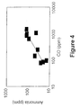
- NH 3 may be depleted below even 2 ppm concurrently with CO removal below about 50 ppm.
- NOx emissions are reduced to low levels while the NH 3 is depleted substantially.
- NOx emissions may be reduced about 80-90% to about 50-200 ppm using NH 3 and HNCO nearly stoichiometrically.
- NOx emissions may be reduced by as much as 99% to levels as low as about 10 ppm using no more than about twice the stoichiometric ratio of NH 3 and HNCO relative to NOx.
- the introduction of hydrocarbon(s) is controlled to maintain a final reaction temperature in the range of about 1400-1550°F.
- the autothermal heat release increases the exhaust gas temperature adiabatically in the absence of heat losses, or alternatively heat transfer surfaces may recover heat from the exhaust gas during the autothermal heating. Such heat recovery, however, should not cool the exhaust gas so excessively as to extinguish the autothermal reactions.
- An autothermal heat release equivalent to an adiabatic temperature increase in the range of about 50-500°F is preferentially utilized in preferred embodiments to achieve a final exhaust gas temperature in the range of about 1400-1550°F for implementing autocatalytic methods in accordance with the present invention.
- the amount of hydrocarbon(s) introduced depends primarily on the initial exhaust gas temperature and any recovery (recycling) of heat released by the autothermal reactions.
- Autocatalytic methods in accordance with the present invention typically utilize residence times no longer than about 1.5 seconds when the initial exhaust gas temperatures are in the range of about 900-1600°F.
- CO and NH 3 typically are depleted faster when the autothermal heating is initiated at higher temperatures in the range of 1050-1600°F.
- reaction residence times in the range of about 0.02-1.0 seconds typically may be sufficient to deplete both CO and NH 3 substantially.
- higher initial exhaust gas temperatures in the range of about 1200-1600°F enable substantial CO and NH 3 depletion within the range of about 0.02-0.5 seconds.
- the introduction of hydrocarbon(s) decreases beneficially when the exhaust gas is preheated to the temperature ranges of about 1050-1600°F or about 1200-1600°F.
- the autothermal heat release need not exceed an amount equivalent to an adiabatic increase of about 50-350°F or about 50-200°F, respectively, so long as the exhaust gas is heated autothermally to a final temperature in the range of about 1400-1550°F.
- this preheating of the exhaust gas also may improve the selectivity of NOx reduction.
- the initial exhaust gas temperatures do not depend on how the exhaust gas is preheated or cooled, so long as the O 2 concentration is maintained in the range of about 2-18% by volume.
- the exhaust gas may be heated or cooled initially using heat transfer surfaces, including any of various methods for preheating the exhaust gas by recovering heat after the exhaust gas is treated using autocatalytic methods as provided herein.
- the exhaust gas is heated directly by the combustion of a supplemental fuel in the exhaust gas.
- the combustion of a supplemental fuel using excess air also may enrich the O 2 concentration in an otherwise O 2 -deficient exhaust gas.
- the supplemental fuel combustion may serve the dual purpose of preheating the exhaust gas and enriching its O 2 concentration.
- the combustion of a supplemental fuel also may serve to preheat a portion of the exhaust gas to ignite more supplemental fuel which is combusted directly in the exhaust gas. If the exhaust gas is preheated using fuel-rich combustion, autocatalytic methods in accordance with the present invention may serve to remove in part or substantial whole the additional contaminants from the fuel-rich combustion. In this context, it is important to note that the "supplemental fuel" is combusted for the purpose of preheating the exhaust gas, and not for chemically enhancing the NOx reduction.
- Autocatalytic methods in accordance with the present invention may be used in combination with various modifications to the combustion process which generates the exhaust gas.
- such modifications may advantageously lower NOx emissions to decrease the introduction of reductant(s) in accordance with the autocatalytic methods of the present invention.
- combustion modifications may beneficially maintain exhaust gas temperatures within the range of about 900-1600°F, or preferably about 1200-1600°F for implementing autocatalytic methods of the present invention.
- combustion modifications may maintain the O 2 concentration above about 2% by volume for implementing autocatalytic methods of the present invention.
- Autocatalytic methods in accordance with the present invention also may be implemented in conjunction with the primary combustion process so that the autothermal heat release is recovered beneficially.
- existing or new surfaces in a heat exchange boiler may serve to recover the autothermal heat release generated in accordance with autocatalytic methods as provided herein.
- the autothermal heating may replace primary fuel for the purpose of generating steam or cracking petrochemicals (as exemplary industrial applications), or the autothermal heating may serve to increase the generating capacity of an existing boiler, etc.
- combustion modifications such as over-fire air are utilized to enable lower NOx emissions from the primary fuel while also enriching O 2 in the exhaust gas.
- the replacement of primary fuel by autothermal oxidation may serve to increase furnace O 2 levels beneficially for the purpose of decreasing unburned carbon on fly ash.
- Such benefits of alternative embodiments of autocatalytic methods in accordance with the present invention may serve to increase overall boiler efficiency while also enhancing the value of byproduct fly ash, possibly avoiding the generation of an otherwise solid waste.
- Autocatalytic methods in accordance with the present invention also may beneficially consume NH 3 breakthrough from a previous exhaust gas treatment using SNCR, for example.
- autocatalytic methods in accordance with the present invention may serve to replace the use of SCR as a means for controlling NH 3 breakthrough from SNCR.
- Such uses of embodiments of the present invention also may preferably apply autocatalytic methods as provided herein in place of SNCR in order to reduce NOx more selectively. It is submitted that, as one exemplary advantage, the better selectivity of autocatalytic methods as provided herein may greatly decrease the introduction and cost of reductant(s), while substantially depleting both CO and NH 3 , and reducing NOx emissions to low levels.
- autocatalytic methods in accordance with the present invention may reduce NOx emissions below most regulatory requirements, application of the present invention may replace the need for expensive catalysts altogether.
- Such autocatalytic activity for removing NH 3 and CO along with NOx may be self-sustained and conducted in a manner so as to not deteriorate with use like solid catalysts.
- autocatalytic methods in accordance with the present invention may avoid the need to replace existing catalysts poisoned by exhaust contaminants.
- autocatalytic methods in accordance with the present invention may serve to enhance SCR applications while minimizing catalyst volume.
- autocatalytic methods as provided herein also may decrease contaminants such as hydrocarbons and soot which may foul catalytic surfaces.
- autocatalytic methods as provided herein may enable the use of more efficient or cost-effective catalyst beds due to both contaminant removal and the control of exhaust gas temperatures.
- autothermal heating may continuously decrease hydrocarbon and soot contaminants while controlling the exhaust gas temperature to the catalyst.
- Emissions of NOx may be maintained at a desired level using a separate injection of NH 3 ahead of the catalyst to minimize reductant(s) introduced to the autocatalytic method. Since autocatalytic NOx reduction need not exceed about 80-90%, reductant(s) may be consumed nearly stoichiometrically, and CO emissions may be substantially depleted in the shortest time possible.
- the material balance curves illustrate the characteristic relationship between temperature and conversion of reactants for exothermic, irreversible reactions.
- the alternative energy balance lines in FIGS. 1(a), (b), and (c) illustrate the potential adiabatic heat release starting from the same initial temperature T.
- the actual conversion and heating depend on satisfying the material and energy balances simultaneously as represented by the points of intersection, which may described as follows.
- FIG. 1(a) the initial temperature and amount of reactants are insufficient for self-sustained adiabatic heating beyond the point of intersection.
- the extent of reaction remains negligible because the heating required to sustain the reaction exceeds the potential amount of heat release from the reaction.
- FIG. 1(b) the larger amount of heat release enables practically complete conversion starting from the same initial temperature. In this case, a high final temperature necessarily results from the high heat release starting at a temperature lower than the ignition temperature as described below.
- FIG. 1(c) illustrates the significance of ignition as a limiting condition for self-sustained adiabatic heating using less heat release.
- Hydrocarbon(s) and CO are known to oxidize by exothermic, irreversible reactions. The heat release from these reactions may self-sustain the conversion of fuels in combustion equipment. Such combustion using excess air produces exhaust gases at high temperatures where the reactant fuel and O 2 are typically preheated above the ignition temperature using a stabilized flame. Such hot oxidizing gases, however, generate NOx emissions thermally and convert fuel nitrogen, including NH 3 and HNCO, to form NOx.
- Such hot oxidizing conditions are avoided by limiting the conversion of reactants in previous teachings related to noncatalytic NOx reduction. According to such teachings, the conversion is limited by a deficiency in either O 2 or the ancillary reducing material. Referring again to FIGS. 1(a) to 1(c) , it may be understood that either of these deficiencies limits both the heat release and the self-sustaining conversion of reactants. The limited conversion, however, tends to necessarily result in the production of air pollutants as described previously.
- Such teachings generally correspond to the introduction of NH 3 , HNCO or hydrocarbon(s) into an O 2 -deficient, fuel-rich exhaust gas or the use of stratified fuel mixtures to generate partial oxidation products.
- the partial oxidation products reduce NOx directly under O 2 -deficient, fuel-rich conditions or lower the effective temperature for selective NOx reduction by NH 3 and HNCO in the presence of excess O 2 .
- FIG. 2 illustrates the autothermal beating of an exhaust gas containing about 10% O 2 and 1555 ppm NOx at an initial temperature of about 920°F.
- the exhaust gas was produced by a heavy duty high speed diesel engine.
- the solid line in FIG. 2 shows the temperature profile when diesel fuel alone was injected to autoignite and autothermally heat the exhaust gas. Temperatures measured using stainless-sheathed type K thermocouples along the gas flowpath never reached 1400°F when diesel fuel was injected alone.
- the final exhaust gas composition contained about 7.6% O 2 , and the initial NOx level was not reduced appreciably by the diesel fuel injection at this high O 2 level.
- the solid rectangles in FIG. 2 illustrate the measured temperatures when cyanuric acid was injected in addition to the diesel fuel.
- the cyanuric acid was injected to decompose and generate HNCO at a molar ratio of about 1.4 with respect to the initial NOx in the exhaust gas.
- the lower temperatures in comparison with diesel fuel alone at residence times less than about 0.4 seconds indicate that the introduction of HNCO slowed the initial autothermal heating of the exhaust gas using the same amount of diesel fuel.
- the additional introduction of HNCO eventually resulted in a higher temperature in excess of 1400°F after about 0.4 seconds, indicating more autothermal heating than the diesel fuel alone.
- the NOx emissions were reduced more than 90%, and the final CO concentration increased from about 185 ppm to about 520 ppm.
- the initially lower temperatures with HNCO generation illustrated in FIG. 2 greatly exceed any cooling effects related to the decomposition and vaporization of cyanuric acid. These lower temperatures reflect an initially slower rate of heat release from the diesel fuel due to the generated HNCO.
- This initial inhibition of the autothermal heating did not last more than about 0.4 seconds. After this initial inhibition, the exhaust gas was heated faster to temperatures above about 1400°F, and both the NOx and CO were substantially depleted as a result of the HNCO generation during the autothermal heating.
- reductant(s) and hydrocarbon(s) are both substantially converted by reactions which release heat autothermally as illustrated in FIGS. 1 and 2 .
- the exhaust gas temperature is increased by adding either more reductant(s) or more hydrocarbon(s). This is contrary to the previous teachings where larger amounts of ancillary reducing materials are added to lower the temperature for NOx reduction or where reductant(s) are added under O 2 -deficient, fuel-rich conditions, etc.
- the NOx emissions were reduced autocatalytically by introducing diesel fuel and cyanuric acid after the exhaust preheating. By preheating the exhaust gas, less diesel fuel was needed for autoignition and autothermal heating to final temperatures in the range of about 1385-1425°F. Using less diesel fuel in comparison with the results illustrated in FIG. 2 actually increased the selectivity of NOx reduction as illustrated in FIG. 3 .
- FIG. 3 illustrates the selectivity and levels of NOx reduction in these single-stage autocatalytic treatments when the exhaust gas was preheated in the range of about 1240-1270°F.
- the initial NOx level of about 700 ppm was reduced as much as about 95% to levels as low as about 31 ppm.
- the NOx was reduced about 80-90% nearly stoichiometrically, and this nearly 100% selectivity declined only gradually when more HNCO was added to reduce NOx further.
- the amount of diesel fuel did not change the operating temperature for selective NOx reduction.
- the autothermal heating of about 480°F in FIG. 2 was decreased in the range of about 100-300°F for the experimental results illustrated in FIGS. 3-5 .
- the substantial depletion of CO and NH 3 confirmed nearly complete conversion of reactants, and the final operating temperature for NOx removal remained near 1400°F.
- Autoignition and autothermal heating represent requirements/conditions to reduce NOx autocatalytically in accordance with the present invention. Without these key conditions, NH 3 and HNCO reduce NOx noncatalytically.
- the previous teachings for noncatalytic NOx reduction preclude any single-stage method for overcoming the limiting inhibition of CO oxidation by NH 3 and HNCO, as may be understood from the previous discussion or a review of such prior teachings.
- This reaction chamber is lined with stainless steel and contains stainless steel baffles. Tests 2-4 were performed using the same exhaust gas and reaction chamber corresponding to the results illustrated in FIGS. 3-5 .
- This reaction chamber is lined with ceramic fiber insulation and contained stainless steel internals which were removed only for Tests 3 and 4.
- Cyanuric acid powder (CYA) was injected pneumatically in Tests 2 and 3 as the source of HNCO.
- An aqueous solution containing about 25% by weight urea was injected as the source of HNCO in Test 4.
- a powdered product of urea decomposition (Mix) was injected pneumatically in Test 1.
- This mixed source of HNCO was estimated to contain about 25% cyanuric acid along with 75% biuret and urea for calculating the molar ratio of HNCO with respect to NOx.
- Tests 1-4 were all performed nearly adiabatically using diesel fuel injection to control the final temperature of the autothermal heating.
- the injection of diesel fuel was decreased in Tests 2-4 where the engine exhaust was preheated prior to the introduction of the diesel fuel and reductant(s).
- the final O 2 concentrations reflect differences in the pneumatic conveying of powdered reductant(s) and the exhaust gas preheating as well as the amount of diesel fuel injected to autoignite and heat the exhaust gases autothermally.
- the comparisons in Table 1 are based on the molar ratio of HNCO with respect to NOx because of the uncertainty in estimating the generation of NH 3 from the mixture of urea decomposition products. This uncertainty is removed when urea and cyanuric acid are compared directly in FIG. 6 .
- the molar ratios are based on generating equal amounts of NH 3 and HNCO from urea, as reported in Combust. Sci. and Tech., Vol. 65, 1989 .
- NH 3 reduces NOx autocatalytically less selectively than HNCO as illustrated in FIG. 6 .
- the data from FIG. 3 are repeated in FIG. 6 for direct comparison of the similar experiments.
- the urea was tested in place of the cyanuric acid by injecting an aqueous solution containing about 25% by weight urea. While the generated mixture of NH 3 and HNCO reduced NOx less selectively than HNCO alone, the NOx was reduced autocatalytically to the same low level using urea or cyanuric acid interchangeably.
- the final temperature of the autocatalytic NOx reduction was maintained at about 1400°F by controlling the introduction of diesel fuel in the preheated exhaust.
- the heat exchanger cooled the treated exhaust by preheating the engine exhaust.
- Supplemental fuel was fired in a burner to preheat the engine exhaust initially as a means for starting the heat recovery.
- the preheated exhaust was introduced to the reaction chamber through a round duct with a 36-inch inside diameter.
- the diesel fuel and powdered cyanuric acid were introduced into this duct.
- the diesel fuel was dispersed in the exhaust gas using pressure atornization from a single liquid spray nozzle.
- the cyanuric acid powder was introduced pneumatically.
- the preheated engine exhaust contained more than about 13.5% O 2 at temperatures above about 1000°F. Under these conditions, stratified ignition was prevented by swirling the entire flowrate of exhaust gas which totaled nearly 13,000 dscfm. Uniform autoignition and autothermal heating were verified visually by the appearance of a chemiluminescence with a substantially uniform blue color as the exhaust gas entered the open reaction chamber.
- the reaction chamber consisted of a round open vessel lined with ceramic fiber insulation.
- the inside diameter of the insulation lining was about 7 feet.
- the blue chemiluminescence was observed to appear in the large open gas space.
- the exposed surfaces in the large open vessel were negligible for catalyzing any reactions.
- the residence time for gas-phase reactions in the open vessel was about 1.3 seconds.
- the treated NOx levels were measured before the cooled exhaust was discharged to the atmosphere.
- the rate of cyanuric acid introduction was controlled to maintain a treated NOx level.
- This NOx level was maintained over a range of engine loads based on both NOx and load measurements.
- the NOx emissions were maintained below a regulatory compliance level using these measurements either individually or collectively.
- NH 3 , HNCO or a combination thereof may be effective for autocatalytic NOx reduction in accordance with the present invention when hydrocarbon(s) autoignite and heat an exhaust gas autothermally under fuel-lean conditions wherein the exhaust gas contains at least about 1% 0 2 .
- reactants including NOx, NH 3 , HNCO, CO, hydrocarbon(s) and other typical exhaust contaminants may be reduced in a substantially concurrent manner.
- both NH 3 and CO may be depleted together when the autocatalytic reactions are self-sustained to a final temperature in the range of about 1400-1550°F.
- NH 3 may be depleted below even 2 ppm concurrently with CO removal below about 50 ppm.
- the concurrent removal of NH 3 and CO is illustrated in FIG. 4 and is unique to the autocatalytic reaction method. Based on this characteristic relationship, CO measurements may be used to reliably indicate the level of NH 3 breakthrough, and in certain preferred embodiments a CO measurement is used in an industrial process to determine whether NH 3 breakthrough is occurring and/or is exceeding a predetermined level.
- Higher final temperatures in the range of about 1400-1550°F primarily deplete the reactants autocatalytically in a shorter residence time when the exhaust gas is preheated above about 900°F.
- a maximum residence time of about 1.5 seconds is decreased below about 1.0 seconds by preheating the exhaust gas above about 1050°F.
- the residence time is decreased below about 0.5 seconds by preheating the exhaust gas above about 1200°F.
- the autocatalytic reactions described herein may be effective for reducing NOx selectively when the exhaust gas is heated autothermally to the temperature range of about 1400-1550°F.
- This range of final temperatures is not highly dependent on the amount of hydrocarbon(s) introduced to autoignite and heat the exhaust gas autothermally. This conflicts with the previous teachings, where larger amounts of ancillary reducing materials are added to lower the effective temperature for NOx reduction h NH 3 and HNCO.
- emissions of NOx may be reduced autocatalytically using NH 3 , HNCO or a combination thereof.
- the NOx emissions are reduced about 80-90% to about 50-200 ppm using NH 3 and HNCO nearly stoichiometrically.
- NOx emissions may be reduced by as much as 99% to levels as low as about 10 ppm using no more than about twice the stoichiometric ratio of NH 3 and HNCO with respect to NOx.
- the NOx emissions may be reduced selectively using a molar ratio of NH 3 and HNCO together with respect to NOx in the range of about 0.5-2.0.
- cyanuric acid, urea and NH 3 may be used in a substantially interchangeable manner for reducing NOx autocatalytically.
- hydrocarbon(s) autoignite and heat the exhaust gas autothermally to temperatures in the range of about 1400-1550°F
- reductant(s) which generate(s) NH 3 , HNCO or a combination thereof may be effective for reducing NOx to a low level in accordance with the present invention.
- autocatalytic methods in accordance with the present invention may be implemented in a single stage.
- the hydrocarbon(s), reductant(s) and exhaust gas may be mixed together for autoignition, autothermal heating and selective NOx reduction.
- the exhaust gas should contain about 2-18% O 2 at a temperature in the range of about 900-1600°F for the spontaneous ignition and autothermal heating to deplete the generated reactants substantially.
- the wavy arrows in FIG. 7 represent the mixing or other dispersion of reactants to maintain fuel-lean conditions wherein the exhaust gas contains at least about 1% O 2 .
- the exhaust gas mixing may start before or after the introduction of hydrocarbon(s) and reductant(s), and the mixing may extend throughout a portion, or even all, of the autothermal heating.
- Baffles or swirl vanes may modify the exhaust gas flowpath to mix the reactants.
- One or more spray nozzles may disperse the hydrocarbon(s) and reductant(s) substantially throughout the cross-section of the exhaust gas flowpath.
- the mixing, dispersion or combination thereof should establish a substantially uniform exhaust gas composition before the appearance of a chemiluminescence.
- the reductant(s) may comprise material(s) selected from the group consisting of NH 3 , HNCO, urea, decomposition products of urea, cyanuric acid or a tautomer of cyanuric acid, compounds which decompose to produce NH 3 as a byproduct, ammonium salts of organic acids, hydrocarbon amines or combinations of the foregoing, whether pure compounds or mixtures, as solids, liquid melts, emulsions, slurries or solutions in water, alcohols, hydrocarbons or oxygenated hydrocarbon solvents.
- material(s) selected from the group consisting of NH 3 , HNCO, urea, decomposition products of urea, cyanuric acid or a tautomer of cyanuric acid, compounds which decompose to produce NH 3 as a byproduct, ammonium salts of organic acids, hydrocarbon amines or combinations of the foregoing, whether pure compounds or mixtures, as solids, liquid melts, e
- the introduction of reductant(s) preferably is controlled to maintain a level of NOx reduction or a final NOx emissions level in the treated exhaust gas.
- continuous measurements of NOx emissions are used to increase or decrease the introduction of reductant(s) as a part of a feedback control system for maintaining a final NOx emissions level (set at a desired, predetermined level, for example).
- NOx emissions source tests can establish characteristic relationships between operating conditions for the combustion equipment and the introduction of reductant(s) needed for a desired level of NOx reduction. Based on these relationships, the continuous monitoring of operating conditions can be used for feedforward control of the NOx emissions reduction. Also, combinations of feedback and feedforward control can reliably maintain final NOx emissions levels despite variations in the exhaust gas flowrate and baseline NOx levels during combustion operations.
- Hydrocarbon(s) utilized in accordance with embodiments of the present invention may comprise material(s) selected from the group consisting of hydrocarbon mixtures such as natural gas, liquefied petroleum gas, alcohols, gasoline, diesel fuel, aviation turbine fuel, various oxygenated hydrocarbons, hydrocarbon amines or any fraction of such mixtures, including purified components such as carbon monoxide, methane, propane, methanol, and ethanol, whether introduced as liquids or vapors.
- the hydrocarbon(s) may include the same liquid, gaseous or vaporous fuels that are combusted to produce the exhaust gas containing NOx.
- Autocatalytic methods in accordance with the present invention in general do not depend on the order in which the reductant(s) and hydrocarbon(s) are introduced into the exhaust gas.
- the introduced hydrocarbon(s) autoignite spontaneously under fuel-lean conditions of about 2-18% O 2 in the exhaust gas.
- the NH 3 , HNCO or combination thereof may be introduced or generated from reductant(s) at any time before or during the fuel-lean autothermal conversion of hydrocarbon(s) and CO in the exhaust gas.
- Self-sustaining autothermal reactions in the gas phase as utilized herein tend not to be adversely affected by other exhaust gas contaminants, including gaseous organics, particulate matter or CO.
- autothermal reactions may serve to at least partially remove these typical exhaust contaminants. This conversion of contaminants may reduce objectionable emissions while decreasing the amount of hydrocarbon(s) required to maintain a final temperature for depleting CO and NH 3 breakthrough in a substantially concurrent manner.
- the introduction of hydrocarbon(s) is controlled to maintain a final temperature in the range of about 1400-1550°F.
- the autothermal heat release increases the exhaust gas temperature adiabatically in the absence of heat losses, or in alternative embodiments heat transfer surfaces may recover heat from the exhaust gas during the autothermal heating. In general, the heat recovery should not cool the exhaust gas so excessively as to extinguish the autothermal reactions before the completion of NOx removal and depletion of CO and NH 3 breakthrough.
- An autothermal heat release equivalent to an adiabatic temperature increase in the range of about 50-500°F is utilized in preferred embodiments to achieve a final exhaust gas temperature in the range of about 1400-1550°F for implementing such autocatalytic methods.
- the amount of hydrocarbon(s) introduced depends primarily on the initial exhaust gas temperature and any recovery of heat released by the autothermal reactions.
- Autocatalytic methods in accordance with preferred embodiments typically require residence times no longer than about 1.5 seconds.
- CO and NH 3 are depleted faster when the autothermal heating is initiated at higher temperatures in the range of about 1050-1600°F.
- reaction residence times in the range of about 0.02-1.0 seconds may be sufficient to deplete both CO and NH 3 substantially.
- Still higher initial exhaust gas temperatures in the range of about 1200-1600°F enable substantial CO and NH 3 depletion within the range of about 0.02-0.5 seconds.
- hydrocarbod(s) decreases beneficially when the exhaust gas is preheated to the temperature ranges of about 1050-1600°F or about 1200-1600°F.
- the autothermal heat release need not exceed an amount equivalent to an adiabatic increase of about 50-350°F or 50-200°F, respectively, so long as the exhaust gas is heated autothermally to a final temperature in the range of about 1400-1550°F.
- This preheating of the exhaust also improves the selectivity of NOx reduction.
- the initial exhaust gas temperatures do not depend on how the exhaust gas is preheated or cooled so long as the O 2 concentration is maintained in the range of about 2-18% by volume.
- the exhaust gas may be heated or cooled initially using heat transfer surfaces, including any of various methods for preheating the exhaust gas by recovering heat after the exhaust gas is treated using autocatalytic methods as provided herein.
- the exhaust gas may be heated directly by the combustion of a supplemental fuel in the exhaust gas.
- the combustion of a supplemental fuel using excess air also may serve to enrich the O 2 concentration in an otherwise O 2 -deficient exhaust gas.
- the supplemental fuel combustion can serve the dual purpose of preheating the exhaust gas and enriching its O 2 concentration.
- the combustion of a supplemental fuel also may serve to preheat a portion of the exhaust gas to ignite more supplemental fuel which is combusted directly in the exhaust gas. If the exhaust gas is preheated using fuel-rich combustion, autocatalytic methods as provided herein may partially remove additional contaminants from the fuel-rich combustion.
- Autocatalytic methods in accordance with the present invention may be used in combination with various modifications to the combustion process for producing the exhaust gas. Such modifications may beneficially lower NOx emissions and maintain exhaust gas temperatures within the range of about 900-1600°F, or preferably about 1200-1600°F, for autocatalytic methods as provided herein, so long as the O 2 concentration remains above about 2% by volume. Such modifications also may beneficially decrease the introduction of both reductant(s) and hydrocarbon(s) in such autocatalytic methods.
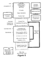
- Autocatalytic methods such as illustrated in FIG. 7 are implemented in alternative embodiments using any of the various techniques for incorporating the exhaust aftertreatment with combustion equipment as illustrated in FIGS. 8 and 9 .
- Autocatalytic methods in accordance with the present invention also may be implemented in conjunction with the primary combustion process so that the autothermal heat release is recovered beneficially as illustrated in FIG. 9 .
- existing or new surfaces in a heat exchange boiler are used in certain embodiments to also recover the autothermal heat release produced with autocatalytic methods as provided herein to replace primary fuel, and may be used, for example, for the purpose of generating steam and/or electricity, or cracking petrochemicals, or the autothermal heating may serve to increase the generating capacity of an existing boiler, etc., as illustrated.
- Combustion modifications such as over-fire air may be used to enable lower NOx emissions from the primary fuel while also enriching O 2 in the exhaust gas.
- the replacement of primary fuel by autothermal heating may serve to increase furnace O 2 levels beneficially for the purpose of decreasing unburned carbon on fly ash.
- Such benefits of autocatalytic methods as provided herein may serve to increase overall boiler efficiency, while also enhancing the value of byproduct fly ash, possibly avoiding the generation of an otherwise solid waste.
- Autocatalytic methods in accordance with the present invention also may beneficially consume NH 3 breakthrough from a previous exhaust gas treatment using SNCR.
- the autocatalytic methods may replace the use of SCR as a means for controlling NH3 breakthrough from SNCR.
- Autocatalytic methods may be preferably applied in place of SNCR in order to reduce NOx more selectively.
- the better selectivity of autocatalytic methods as provided herein may greatly decrease the consumption and cost of reductant(s), while depleting both CO and NH 3 in a substantially concurrent manner, and reducing NOx emissions to lower levels.
- Autocatalytic methods in accordance with the present invention may reduce NOx emissions below most regulatory requirements, and the present invention typically supplants the need for expensive catalysts altogether.
- Autocatalytic activity for removing NH 3 and CO along with NOx in accordance with the present invention may be self-sustained and in a manner that does not deteriorate with use like solid catalysts.
- autocatalytic methods as provided herein may avoid the need to replace existing catalysts poisoned by exhaust contaminants.
- autocatalytic methods as provided herein may serve to enhance SCR applications while minimizing the catalyst volume.
- autocatalytic methods also may decrease contaminants such as hydrocarbons and soot which may foul catalytic surfaces.
- autocatalytic methods may enable the use of more efficient or cost-effective catalyst beds due to both contaminant removal and the control of exhaust gas temperatures.
- the autothermal heating continuously decreases hydrocarbon and soot contaminants while controlling the exhaust gas temperature to the catalyst. Emissions of NOx are maintained at the required level using a separate injection of NH 3 ahead of the catalyst to minimize reductant(s) utilized with the autocatalytic method. In many such situations, the autocatalytic NOx reduction need not exceed about 80-90%, so reductant(s) are converted nearly stoichiometrically and CO emissions are depleted substantially in the shortest time possible.
- autocatalytic methods may remove excess NH3 while reducing NOx to low levels.
- nonuniform distributions of NOx in the exhaust gas tend to only decrease the selectivity of NOx reduction by the autocatalytic methods.
- autocatalytic methods may replace the need for mixing the exhaust gas, especially when such autocatalytic methods are combined with SCR to achieve ultra-low emissions levels.
- Autocatalytic methods as provided herein are uniquely suited for combination with catalytic air heater elements.
- Such catalytic elements replace existing heat transfer surfaces in rotary regenerative air heaters, such as described in U.S. Pat. Nos. 4,602,673 , 4,678,643 , 4,719, 094 and 4,867,953 .
- Using autocatalytic methods to control temperature as well as uniform NOx levels ahead of the catalyst greatly enhances the capability for both NOx and NH 3 removal within the limited volume for the installation of catalytic elements in existing air heaters.
- replacement of air heater elements also may enhance the recovery of heat released with autocatalytic methods. Increasing exhaust gas temperatures enhances heat recovery by all existing surfaces downstream from the heat release, but this enhancement does not generally recover all of the autothermal heat release. Complete recovery of the autothermal heat release usually requires the installation of some new heat transfer surfaces. Replacement air heater elements with improved surfaces may conveniently be utilized to complete the recovery of the autothermal heat release.
- This replacement of air heater elements may uniquely complete the recovery of the autothermal heat release while also providing catalytic surfaces to achieve ultra-low levels of both NOx and NH 3 .
- such modifications may even enable improvements to boiler efficiency by lowering stack gas temperatures. Boiler efficiency may be improved even further when autocatalytic methods are implemented in combination with combustion modifications to decrease the unburned carbon on fly ash.
- autocatalytic methods as provided herein are implemented by controlling the final temperature of autothermal heating at a level in the range of about 1400-1550°F.
- This controlled condition preferably is achieved using one or more injection nozzles for the introduction of hydrocarbon(s) and reductant(s).
- Such nozzles may inject the hydrocarbon(s) and reductant(s) separately or concurrently, as mixtures, solutions, emulsions, slurries or combined chemical structures, using combinations of solids, liquids, and gases.
- hydrocarbon(s) and reductant(s) may involve the use of pressurized gas to convey or atomize the injected material(s).
- the pressurized gas may consist of steam, air, exhaust gas or the gaseous or vaporous forms of the hydrocarbon(s) or reductant(s).
- compressed air When compressed air is used to convey or atomize any of the injected material(s), the compressed air may beneficially enrich the O 2 concentration in the exhaust gas.
- one or more injection nozzles are arranged in various ways so long as the distribution of hydrocarbon(s) and reductant(s) in the exhaust gas is sufficiently uniform to avoid localized heating beyond the temperature range of about 1400-1550°F.
- the distribution and mixing of injected material(s) may include various uses of vanes or baffles to swirl the exhaust gas or to generate turbulent mixing eddies. Such methods or their combinations should disperse the injected hydrocarbon(s) in a substantially uniform manner before the appearance of a chemiluminescence.
- Locating such baffles or swirl vanes either before or after the injection locations may enable the continued mixing of the exhaust gas throughout a portion, or even all, of the flowpath during autothermal heating. Any such modifications to the gas flowpath preferably extend over the entirety of its cross-section.
- the use of such methods for mixing the exhaust gas also may enable the introduction of hydrocarbon(s) and reductant(s) using a variety of convenient nozzle configurations such as wall injectors or injection grids.
- the use of injection grids may avoid the need for modifying the gas flowpath.
- a multiplicity of nozzles preferably are used to distribute hydrocarbon(s) and reductant(s) over the cross-section of the gas flowpath.
- Such injection grids may resemble the well known commercial practice of distributing prevaporized NH 3 ahead of solid catalysts in SCR methods.
- the injection grids may consist of liquid nozzles using either pressure or gas atomization.
- the preferred atomization depends on the degree of exhaust gas mixing. In certain embodiments, no atomization is needed if the exhaust gas is well mixed by turbulent flow conditions.
- autocatalytic methods in accordance with the present invention may be implemented in ducts as large as three feet or more in diameter using only a single injector when the exhaust gas is swirled sufficiently to mix the vaporized hydrocarbon(s) and reductant(s). Atomized drops in the range of about 20-500 microns, however, are preferred in embodiments where the mixing depends primarily on dispersion.
- Hydrocarbon(s) and reductant(s) are preferably introduced in their most concentrated form.
- Using concentrated mixtures or solutions tends to minimize heat losses due to the sensible and latent heats of carrier liquids or gases.
- the dilution of injected material(s) may enhance their dispersion in some cases.
- aqueous solutions of urea may require dilution in order to supply a multiplicity of nozzles needed for adequate dispersion or to decrease the size of reductant particles remaining after water evaporation from atomized drops.
- commercial aqueous solutions containing about 50% by weight urea are diluted below even a 35% concentration that is typically used to prevent crystallization in storage tanks and other distribution equipment.
- the distribution of hydrocarbon(s) or reductant(s) to injectors must prevent degradation of the material(s) prior to injection. Such degradation can result in the plugging of distribution networks or nozzle orifices. While heating or vaporization of some material(s) may enhance their injection without degradation, other material(s) may require a means to prevent such heating or vaporization. In embodiments where the later may occur, the atomizing gas also may serve as a cooling medium or insulating boundary for preventing degradation before injection.
- Chemical additives also may help to prevent scaling or plugging in distribution networks prior to the injection of hydrocarbon(s) or reductant(s).
- Such chemical additives may comprise any of the commercially available formulations for this purpose.
- the use of distilled or de-ionized water for aqueous solutions may prevent scaling in storage tanks, piping and other equipment or instrumentation used to pressurize, meter, transport, distribute and inject chemical reductant(s) such as NH 3 or urea.
- chemical reductant(s) such as NH 3 or urea.
- scaling and corrosion are minimized by selecting proper materials of construction throughout these systems, depending on the injected material(s).
- a wide variety of methods for reducing NOx from industrial exhaust gases are provided, which may comprise autothermally heating the exhaust gas using one or more hydrocarbons in the presence of NH 3 , HNCO or a combination thereof, wherein the autothermal heating is under conditions effective for selectively reducing the NOx autocatalytically.
- Such methods may consist of the steps of: controlling the initial temperature and composition of an exhaust gas in the ranges of about 900-1600°F and about 2-18% O 2 , respectively, effective for autoignition of hydrocarbon(s); controlling the introduction of hydrocarbon(s) to autoignite and release heat autothermally effective for self-sustaining autocatalytic reactions under fuel-lean conditions wherein the exhaust gas contains at least about 1% O 2 and is heated to a final temperature in the range of about 1400-1550°F; introducing reductant(s) for NOx into the exhaust gas wherein NH 3 , HNCO or a combination thereof are generated from the reductant(s); wherein NOx is reduced selectively, and the NH 3 , HNCO and hydrocarbon(s), including byproduct CO are depleted substantially.
- a method for autothermally heating exhaust gases using hydrocarbon(s) so that NH 3 , HNCO or a combination thereof are effective for selectively reducing NOx autocatalytically A method for autothermally heating exhaust gases to temperatures in the range of about 1400-1550°F using hydrocarbon(s) to remove CO so that NH 3 , HNCO or a combination thereof are concurrently effective for selectively reducing NOx autocatalytically.
- a method including the steps of: controlling the initial temperature and composition of an exhaust gas effective for autoignition of hydrocarbon(s); controlling the introduction of hydrocarbon(s) to autoignite and release heat autothermally effective for self-sustaining autocatalytic reactions under fuel-lean conditions wherein the exhaust gas contains at least about 1% O 2 ; introducing reductant(s) for NOx into the exhaust gas wherein NH 3 , HNCO or a combination thereof are generated from the reductant(s); wherein NOx is reduced selectively, and the NH 3 , HNCO and hydrocarbon(s), including byproduct CO are depleted substantially.
- a method for autothermally heating exhaust gases using hydrocarbon(s) so that NH 3 , HNCO or a combination thereof are effective for selectively reducing oxides of nitrogen A method for selectively reducing oxides of nitrogen in an exhaust gas using NH 3 , HNCO or a combination thereof while hydrocarbon(s) autoignite and heat the exhaust gas autothermally.
- Still other methods in accordance with the present invention include the following.
- Yet other methods in accordance with the present invention include the following.
- Still other methods in accordance with the present invention include the following.
- a method for concurrently removing oxides of nitrogen and carbon monoxide from an exhaust gas using NH 3 , HNCO or a combination thereof while hydrocarbon(s) autoignite and heat the exhaust gas autothermally A method for concurrently removing oxides of nitrogen and carbon monoxide from an exhaust gas using NH 3 , HNCO or a combination thereof while hydrocarbon(s) autoignite and heat the exhaust gas autothermally, substantially depleting residual concentrations of unburned hydrocarbons, HNCO and NH 3 .
- a method for treating an exhaust gas to remove oxides of nitrogen along with carbon monoxide and other combustible contaminants using NH 3 , HNCO or a combination thereof while hydrocarbon(s) autoignite and heat the exhaust gas autothermally A method for treating an exhaust gas to remove oxides of nitrogen along with carbon monoxide and other combustible contaminants using NH 3 , HNCO or a combination thereof while hydrocarbon(s) autoignite and heat the exhaust gas autothermally, substantially depleting residual concentrations of HNCO and NH 3
- a method including the steps of: introducing reductant(s) for oxides of nitrogen into the exhaust gas so that the reductant(s) generate NH 3 , HNCO or a combination thereof; introducing hydrocarbon(s) into an exhaust gas containing about 2-18% oxygen at a temperature in the range of about 900-1600°F so that the hydrocarbon(s) autoignite in the exhaust gas; wherein the oxides of nitrogen are reduced selectively while the exhaust gas is heated autothermally by self-sustained autocatalytic reactions.
- NOx in the exhaust gas may be reduced nearly stoichiometrically by as much as 80-90%; NOx in the exhaust gas may be selectively reduced by as much as about 99%; NOx in the exhaust gas may be reduced to a level in the range of about 10-200 ppm; and NH 3 and HNCO together may be in the range of about 0.5-2.0 or 0.5-4.0 molar ratio with respect to the NOx in the exhaust gas.
- Higher molar ratios of NH 3 and HNCO together up to about 4.0 may generally increase NOx reduction without appreciably increasing NH 3 breakthrough using autocatalytic methods in accordance with the present invention, but the cost-effectiveness of such higher molar ratio embodiments diminishes when NH 3 and HNCO, etc. are used at levels in excess of twice the stoichiometric ratio with respect to baseline NOx levels.
- the selective NOx reduction and the depletion of residual NH 3 and HNCO may contribute to the exhaust gas heating;
- the oxidation of combustible contaminants in the exhaust gas may contribute to exhaust gas heating;
- the exhaust gas temperature may be initially in the range of about 900-1600°F and the exhaust gas initially may contain O 2 in the range of about 2-18%;
- the autothermal heat release may be initiated by autoignition of hydrocarbon(s) in the exhaust gas;
- the exhaust gas may be heated substantially uniformly by the autoignition of hydrocarbon(s) and the self-sustained autothermal heat release from autocatalytic reactions;
- the autocatalytic reactions may be self-sustained in the autothermally heated exhaust gas even when a portion of the heat released is recovered by heat transfer surfaces;
- the heat release may be equivalent to a uniform adiabatic increase of about 50-500°F in the exhaust gas temperature;
- the exhaust gas may be heated within about 0.02-1.5 seconds to a final temperature;
- the exhaust gas may be heated
- the residual concentrations of CO and NH 3 may be depleted together autocatalytically in the exhaust gas at a final temperature in the range of about 1400-1550°F; the final temperature may be controlled in the range of about 1400-1550°F to maintain the residual CO concentration below about 50 ppm while depleting the residual NH 3 below about 2 ppm;
- the hydrocarbon(s) may consist of material(s) selected from the group consisting of hydrocarbon mixtures such as natural gas, liquefied petroleum gas, alcohols, gasoline, diesel fuel, aviation turbine fuel, various oxygenated hydrocarbons, hydrocarbon amines, or any fraction of such mixtures, including purified components such as carbon monoxide, methane, propane, methanol, and ethanol, either as liquids or vapors; the hydrocarbons(s) may consist of the same material(s) as the liquid, gaseous, or vaporous fuel used to produce or otherwise heat the exhaust gas initially in the temperature range of about 900-1600°F; the hydrocarbon(s) may be introduced into
- the hydrocarbon(s) and any carrier or atomizing gas may be pressurized and/or metered; a final temperature may be measured at one or more locations throughout the cross-section of the exhaust gas flowpath and the amount of introduced hydrocarbon(s) may be controlled to maintain the measured temperature(s) at a level in the range of about 1400-1550°F; the final CO concentration may be measured at one or more locations throughout the cross-section of the exhaust gas flowpath downstream from the temperature measurement(s); the final CO measurement(s) may be used to verify a level of CO depletion corresponding to the final temperature(s) for controlling the introduction of hydrocarbon(s); NH 3 , HNCO or a combination thereof may be introduced into the exhaust gas; NH 3 , HNCO or a combination thereof may be generated by vaporization, decomposition or catalytic conversion of reductant(s) which may consist of material(s) selected from the group consisting of NH 3 , HNCO, cyanuric acid or a tautomer of cyanuric acid
- reductant(s) may be injected directly to vaporize or decompose in the exhaust gas; the reductant(s) may be injected prior to the introduction of hydrocarbon(s); the reductant(s) may be injected after the introduction of hydrocarbon(s); the reductant(s) may be injected concurrently with the introduced hydrocarbon(s) as mixtures, solutions, emulsions, slurries, atomizing gases, atomized liquids or combined chemical structures; the reductant(s) may be injected substantially throughout a cross-section or around a perimeter of the exhaust gas flowpath using one or more nozzles, including a multiplicity thereof; the reductant(s) may be injected using a carrier or atomizing gas such as steam, compressed air, pressurized exhaust gas, gaseous or vaporous hydrocarbon(s) or any gaseous or vaporous NH 3 compositions; the reductant(s) are atomized to form liquid drops with diameters in the range of about 20-500 microns; the reductant(s)
- baseline NOx levels in the exhaust gas may be measured with respect to an operating condition of combustion equipment that produces the exhaust gas and the amount of reductant(s) injected to maintain a predetermined level of NOx reduction or a predetermined final NOx level in the exhaust gas may be controlled throughout the operating range of the combustion equipment; an operating condition of the combustion equipment may be monitored to provide a basis for estimating the baseline NOx emissions throughout the operating range of the combustion equipment, either continuously or on a periodic basis; the amount of injected reductant(s) may be controlled to generate NH 3 and HNCO together at a level in the range of about 0.5-2.0 molar ratio with respect to the baseline NOx depending on a measurement of the operating condition for the combustion equipment; the final NOx level may be measured at one or more locations throughout the cross-section of the exhaust gas flowpath downstream from the autothermal heating and any temperature measurement(s) may be used to control the introduction of hydrocarbon(s); the final NOx level(s) may be used to verify the effectiveness of selective NOx reduction corresponding to an amount of introduced
- the dilution water and any carrier or atomizing gas may be treated to prevent the formation of deposits or scale in surge tanks, piping, and other equipment or instrumentation used to pressurize, meter, transport, distribute, and inject the dilution water, carrier gas, or atomizing gas; concentrated aqueous solutions consisting of NH 3 , urea, or combinations thereof may be formulated and/or prepared in water containing dissolved nitrogen in the range of about 15-30% by weight; the concentrated aqueous solution may be prepared using distilled or de-ionized water to prevent the formation of deposits or scale in storage tanks, piping and other equipment or instrumentation used to pressurize, meter, transport, distribute, and inject the dissolved reductant(s) as concentrated or diluted solutions in water; the concentrated aqueous solution may contain chemical additives to prevent the formation of deposits or scale in storage tanks, piping, and other equipment or instrumentation used to pressurize, meter, transport, distribute and inject the dissolved reductant(s) as concentrated or diluted solutions in water.
- the exhaust gas may be preheated or precooled to a temperature in the range of about 900-1600°F before the introduction of hydrocarbon(s); the exhaust gas may be preheated or precooled to a temperature in the range of about 1050-1600°F so that the exhaust gas is heated autothermally in about 0.02-1.0 seconds to a final temperature in the range of about 1400-1550°F by a heat release equivalent to an adiabatic increase of about 50-350°F effective for enhancing the selectivity of autocatalytic NOx reduction; the exhaust gas may be preheated or precooled to a temperature in the range of about 1200-1600°F so that the exhaust gas is heated autothermally in about 0.02-0.5 seconds to a final temperature in the range of about 1400-1550°F by a heat release equivalent to an adiabatic increase of about 50-200°F effective for enhancing the selectivity of autocatalytic NOx reduction; the exhaust gas temperature may be controlled at a level in the range of about 900-1600°F before the introduction of hydrocarbon
- the temperature of the autothermally heated exhaust gas may be controlled at a level in the range of about 1400-1550°F in order to maintain the preheated exhaust gas temperature in the range of about 900-1350°F using a heat exchanger; a supplemental fuel may be combusted to preheat the exhaust gas in the temperature range of about 900-1350°F; a supplemental fuel may be combusted directly in the exhaust gas; the exhaust gas may be preheated by mixing with the products from combustion of supplemental fuel and air; a supplemental fuel may be combusted directly in the exhaust gas after a portion of the exhaust gas is preheated by mixing with the products from combustion of supplemental fuel and air; the supplemental fuel may consist of the same hydrocarbon(s) which autoignite and maintain the autocatalytic heat release in the exhaust gas; the supplemental fuel may consist of the same material(s) used to produce the exhaust gas; and the exhaust gas may be enriched to contain in the range of about 2-5% O 2 using excess air for the combustion of supplemental fuel.
- the exhaust gas flowpath may be modified to mix the injected materials(s) as well as the exhaust gas composition; the exhaust gas flowpath may be modified before the introduction of hydrocarbon(s); the exhaust gas flowpath may be modified after the introduction of hydrocarbon(s); the exhaust gas flowpath may be modified both before and after the introduction of hydrocarbon(s); the mixing effects may extend substantially throughout the cross-section of the exhaust gas flowpath and may continue to mix the exhaust gas composition for a portion, or even all, of the autothermal heating; vanes may be used to swirl the gas flowpath, either as a single swirl flow or as a multiplicity of mixing swirl flows; baffles may be used to generate a multiplicity of turbulent mixing eddies; and the introduced hydrocarbon(s) may be mixed substantially uniformly before the appearance of a visible chemiluminescence.
- heat may be recovered from the autothermally heated exhaust gas using heat transfer surfaces between the exhaust gas and the heat recovery fluid; heat may be recovered from the exhaust gas to heat another fluid such as steam, water, combustion air or a petrochemical composition; a petrochemical composition may be cracked; steam may be generated; and the steam may be coupled to a turbine and operate machinery or generate electricity.
- the production of the exhaust gas containing NOx may be modified to maintain a temperature in the range of about 900-1600°F and to contain in the range of about 2-18%O 2 ;
- the production of the exhaust gas may be modified by staging the primary combustion using secondary air or over-fire air to decrease the formation of NOx;
- the fuel consumed to produce the exhaust gas may be reduced by an amount of heat release less than or equal to the heat released by autocatalytic reactions in the exhaust gas;
- O 2 enrichment of the primary combustion may decrease the formation of combustible contaminants in the exhaust gas, including gaseous organics, soot, and unburned carbonaceous materials or particulate matter; and the O 2 enrichment of coal combustion may decrease unburned carbon on fly ash.
- a fuel may be combusted in a heat exchange boiler and the exhaust gas may be cooled before the introduction of hydrocarbon(s) which autoignite and maintain autocatalytic heat release in the exhaust gas; a petrochemical composition may be cracked; steam may be generated; the steam may be coupled to a turbine and operate machinery or generate electricity; a fuel may be combusted in an internal combustion engine; the internal combustion engine may be coupled to an electric generator, and electricity may be generated; the internal combustion engine may be coupled to a pump or compressor, and pressure and/or fluid flow may be generated using the pump or compressor; the internal combustion engine may be coupled to machinery, and the machinery may be operated so as to produce mineral resources; the internal combustion engine may be coupled to power mobile equipment, and personnel, materials, products or minerals may be transported and/or processed; and waste may be combusted in a waste to heat incinerator, and combustible waste may be disposed of.
- NH 3 breakthrough may be generated from a previous noncatalytic process for selectively reducing NOx, and NOx may be noncatalytically reduced at temperatures above 1600°F prior to the autothermal exhaust gas heating and autocatalytic NOx reduction; a portion of the remaining NOx may be catalytically reduced using a solid catalytic surface and additional generation of NH 3 , HNCO or combinations thereof after the autothermal exhaust gas heating; the exhaust gas may be heated autothermally to control the temperature for the subsequent catalytic NOx reduction using a solid catalytic surface; the first stage of gas-phase autocatalytic NOx reduction may lower the inlet NOx level to the solid catalytic surface; the first stage of autothermal heating may decrease exhaust gas contaminants such as hydrocarbons, soot, CO and particulate matter; and the solid catalytic surface may serve the dual purpose of decreasing the final NOx level and recovering a portion of the autothermal heat release.
- reductant(s) may be injected or generated incrementally as the exhaust gas is autothernally heated. Staging the injection or generation of reductant(s) replenishes NH 3 , HNCO, or combinations thereof in the exhaust gas as reactants are consumed for NOx reduction. This staging is effective for NOx reduction so long as the autocatalytic reactions continue to heat the exhaust gas.
- the injection of reductant(s) may be staged using one or more nozzles, including a multiplicity thereof, along the exhaust gas flowpath.
- NH 3 , HNCO, or a combination thereof may be generated incrementally by the decomposition or vaporization of reductant(s) which are injected as solids, liquid melts, emulsions, slurries, or solutions.
- This alternative staging may involve different reductant(s), solution concentrations, and spray droplet sizes in order to modify the generation of NH 3 , HNCO, or a combination thereof during the autothermal heating of the exhaust gas.
- the reductant(s) may consist of a dilute aqueous solution consisting of NH 3 , urea, or a combination thereof in water containing dissolved nitrogen in the range of about 2-15% by weight.
- the method for reducing NOx from an exhaust gas comprises autothermally heating the exhaust gas using one or more hydrocarbons in the presence of NH 3 , HNCO or a combination thereof, wherein the autothermal heating is under conditions effective for reducing the NOx autocatalytically.
- the NOx in the exhaust gas is reduced nearly stoichiometrically by as much as 80-90%.
- the NOx in the exhaust gas is selectively reduced by as much as about 99%.
- the NOx in the exhaust gas is reduced to a level in the range of about 10-200 ppm.
- NH 3 and HNCO together are in the range of about 0.5-2.0 molar ratio with respect to the NOx in the exhaust gas.
- the exhaust gas temperature is initially in the range of 900-1600°F and the exhaust gas initially contains O 2 in the range of about 2-18%.
- the autothermal heat release is initiated by autoignition of hydrocarbon(s) in the exhaust gas.
- the autocatalytic reactions are self-sustained in the autothermally heated exhaust gas even when a portion of the heat released is recovered by heat transfer surfaces.
- the heat release is equivalent to a uniform adiabatic increase of about 50-500°F in the exhaust gas temperature.
- the exhaust gas is heated within about 0.02-1.5 seconds to a final temperature.
- the exhaust gas is heated to a final temperature in the range of about 1400-1550°F.
- the exhaust gas contains at least about 1% O 2 , at a final temperature in the range of about 1400-1550°F.
- residual concentrations of hydrocarbons, CO, NH 3 and HNCO are depleted substantially at a final temperature in the range of about 1400-1550°F.
- the CO is oxidized below a residual concentration of about 2000 ppm.
- the CO is oxidized below a residual concentration of about 500 ppm.
- the residual concentration of CO is maintained at a level below about 500 ppm by controlling a final exhaust gas temperature in the range of about 1400-1550°F.
- the residual concentration of NH 3 is maintained at a level below about 20 ppm by controlling a final exhaust gas temperature in the range of about 1400-1550°F.
- the residual concentrations of CO and NH 3 are depleted together autocatalytically in the exhaust gas at a final temperature in the range of about 1400-1550°F.
- the final temperature is controlled in the range of about 1400-1550°F to maintain the residual CO concentration below about 50 ppm while depleting the residual NH 3 below about 2 ppm.
- the hydrocarbon(s) comprise material(s) selected from the group consisting of hydrocarbon mixtures such as natural gas, liquefied petroleum gas, alcohols, gasoline, diesel fuel, aviation turbine fuel, various oxygenated hydrocarbons, hydrocarbon amines or any fraction of such mixtures, including purified components such as carbon monoxide, methane, propane, methanol and ethanol, either as liquids or vapors.
- hydrocarbon mixtures such as natural gas, liquefied petroleum gas, alcohols, gasoline, diesel fuel, aviation turbine fuel, various oxygenated hydrocarbons, hydrocarbon amines or any fraction of such mixtures, including purified components such as carbon monoxide, methane, propane, methanol and ethanol, either as liquids or vapors.
- the hydrocarbon(s) are introduced substantially throughout a cross-section or around a perimeter of the exhaust gas flowpath using one or more nozzles, including a multiplicity thereof.
- the hydrocarbon(s) are introduced as liquid drops with diameters in the range of about 20-500 microns.
- the hydrocarbon(s) are introduced in the exhaust gas using a carrier or atomizing gas such as steam, compressed air, pressurized exhaust gas, gaseous or vaporous hydrocarbon(s) or any gaseous or vaporous NH 3 compositions.
- a carrier or atomizing gas such as steam, compressed air, pressurized exhaust gas, gaseous or vaporous hydrocarbon(s) or any gaseous or vaporous NH 3 compositions.
- a twenty-fourth embodiment related to the first embodiment, further comprises the steps of measuring a final temperature at one or more locations throughout the cross-section of the exhaust gas flowpath and controlling the amount of introduced hydrocarbon(s) to maintain the measured temperature(s) at a level in the range of about 1400-1550°F.
- a twenty-fifth embodiment, related to the twenty-fourth embodiment, further comprises the step of measuring a final CO concentration at one or more locations throughout the cross-section of the exhaust gas flowpath downstream from the temperature measurement(s).
- a twenty-sixth embodiment, related to the twenty-fifth embodiment, further comprises the step of using the final CO measurement(s) to verify a level of CO depletion corresponding to the final temperature(s) for controlling the introduction of hydrocarbon(s).
- a twenty-seventh embodiment, related to the first embodiment, further comprises the step of generating NH 3 HNCO or a combination thereof by vaporization, decomposition, or catalytic conversion of reductant(s) which comprise any of the material(s) selected from the group consisting of NH 3 , HNCO, cyanuric acid or a tautomer of cyanuric acid, urea, decomposition products of urea, compounds which decompose to produce NH 3 as a byproduct, ammonium salts of organic acids, hydrocarbon amines, or combinations of the foregoing, whether pure compounds or mixtures, as solids, liquid melts, emulsions, slurries or solutions in water, alcohols, hydrocarbons, or oxygenated hydrocarbon solvents.
- reductant(s) which comprise any of the material(s) selected from the group consisting of NH 3 , HNCO, cyanuric acid or a tautomer of cyanuric acid, urea, decomposition products
- the NH 3 , HNCO or a combination thereof are generated prior to the introduction of hydrocarbon(s).
- the NH 3 , HNCO or a combination thereof are generated after the introduction of hydrocarbon(s).
- the NH 3 , HNCO or a combination thereof are generated concurrently with the hydrocarbon(s).
- the NH 3 , HNCO, or a combination thereof are generated incrementally during the autothermal heating of the exhaust gas.
- generated NH 3 , HNCO, or a combination thereof are injected incrementally during the autothermal heating of the exhaust gas.
- a thirty-third embodiment, related to the twenty-seventh embodiment, further comprises the step of injecting reductant(s) directly to vaporize or decompose in the exhaust gas.
- the reductant(s) are injected prior to the introduction of hydrocarbon(s).
- the reductant(s) are injected after the introduction of hydrocarbon(s).
- the reductant(s) are injected concurrently with the introduced hydrocarbon(s) as mixtures, solutions, emulsions, slurries, atomizing gases, atomized liquids or combined chemical structures.
- the reductant(s) comprise a concentrated aqueous solution consisting of NH 3 , urea or combinations thereof in water containing dissolved nitrogen in the range of about 15-30% by weight.
- the reductant(s) comprise a dilute aqueous solution consisting of NH 3 , HNCO, or a combination thereof in water containing dissolved nitrogen in the range of about 2-15%.
- the dissolved reductant(s), solution concentration, and spray droplet size are selected to generate NH 3 , HNCO, or a combination thereof incrementally during the autothermal heating of the exhaust gas.
- a fortieth embodiment, related to the thirty-third embodiment, further comprises the steps of measuring baseline NOx levels in the exhaust gas with respect to an operating condition of combustion equipment that produces the exhaust gas and controlling the amount of reductant(s) injected to maintain a level of NOx reduction or a final NOx level in the exhaust gas throughout the operating range of the combustion equipment.
- a forty-first embodiment, related to the fortieth embodiment, further comprises the step of monitoring an operating condition of the combustion equipment to provide a basis for estimating the baseline NOx emissions throughout the operating range of the combustion equipment, either continuously or frequently.
- the amount of injected reductant(s) is controlled to generate NH 3 and HNCO together at a level in the range of about 0.5-2.0 molar ratio with respect to the baseline NOx depending on a measurement of the operating condition for the combustion equipment.
- a forty-third embodiment, related to the thirty-third embodiment, further comprises the step of measuring a final NOx level at one or more locations throughout the cross-section of the exhaust gas flowpath downstream from the autothermal heating and any temperature measurement(s) used to control the introduction of hydrocarbon(s).
- a forty-fourth embodiment, related to the forty-third embodiment, further comprises the step of using the final NOx level(s) to verify the effectiveness of selective NOx reduction corresponding to an amount of introduced NH 3 and HNCO or an amount of reductant(s) injected to generate NH 3 , HNCO or a combination thereof.
- a forty-fifth embodiment related to the forty-forth embodiment, further comprises the step of controlling the amount of introduced NH 3 and HNCO or the amount of reductant(s) injected to maintain a final NOx level in the exhaust gas.
- a forty-sixth embodiment, related to the first embodiment, further comprises either alternative step of preheating or precooling the exhaust gas to a temperature in the range of about 900-1600°F before the introduction of hydrocarbon(s).
- the exhaust gas is preheated or precooled to a temperature in the range of about 1050-1600°F so that the exhaust gas is heated autothermally in 0.02-1.0 seconds to a final temperature in the range of about 1400-1550°F by a heat release equivalent to an adiabatic increase of about 50-350°F effective for enhancing the selectivity of autocatalytic NOx reduction.
- the exhaust gas is preheated or precooled to a temperature in the range of about 1200-1600°F so that the exhaust gas is heated autothermally in 0.02-0.5 seconds to a final temperature in the range of about 1400-1550°F by a heat release equivalent to an adiabatic increase of about 50-200°F effective for enhancing the selectivity of autocatalytic NOx reduction.
- a forty-ninth embodiment, related to the first embodiment, further comprises the step of combusting a supplemental fuel to preheat the exhaust gas in the temperature range of about 900-1350°F.
- a supplemental fuel is combusted directly in the exhaust gas.
- the introduced hydrocarbon(s) are mixed substantially uniformly before the appearance of a visible chemiluminescence.
- a fifty-second embodiment, related to the first embodiment, further comprises the step of recovering heat from the autothermally heated exhaust gas using heat transfer surfaces between the exhaust gas and the heat recovery fluid.
- heat is recovered from the exhaust gas to heat another fluid such as steam, water, combustion air or a petrochemical composition.
- a fifty-fourth embodiment, related to the fifty-second embodiment, further comprises the step of cracking a petrochemical composition.
- a fifty-fifth embodiment, related to the fifty-second embodiment, further comprises the step of generating steam.
- a fifty-sixth embodiment related to the fifty-fifth embodiment, further comprises the steps of coupling the steam to a turbine and operating machinery or generating electricity.
- a fifty-seventh embodiment related to the first embodiment, further comprises the step of generating NH 3 breakthrough from a previous noncatalytic method for selectively reducing NOx, the method further comprising the noncatalytic reduction of NOx at temperatures above 1600°F prior to the autothermal exhaust gas heating and autocatalytic NOx reduction.
- a fifty-eighth embodiment related to the first embodiment, further comprises the step of catalytically reducing a portion of the remaining NOx using a solid catalytic surface and additional generation of NH 3 , HNCO, or combinations thereof after the autothermal exhaust gas heating.
- the exhaust gas is heated autothermally to control the temperature for the subsequent catalytic NOx reduction using a solid catalytic surface.
- the first stage of gas-phase autocatalytic NOx reduction lowers the inlet NOx level to the solid catalytic surface.
- the first stage of autothermal heating decreases exhaust gas contaminants such as hydrocarbons, soot, CO and particulate matter.
- the solid catalytic surface serves the dual purpose of decreasing the final NOx level and recovering a portion of the autothermal heat release.
- a sixty-third embodiment comprises the steps of: controlling the initial temperature and composition of an exhaust gas in the ranges of about 900-1600°F and about 2-18% O 2 , respectively, effective for autoignition of hydrocarbons; controlling the introduction of hydrocarbons to autoignite and release heat autothermally effective for self-sustaining autocatalytic reactions under fuel-lean conditions wherein the exhaust gas contains at least 1% O 2 and is heated to a final temperature in the range of about 1400-1550°F; introducing one or more reductants for NOx into the exhaust gas wherein NH 3 , HNCO or a combination thereof are generated from the reductant(s); wherein NOx is reduced, and the NH 3 , HNCO and hydrocarbons, including any byproduct CO are depleted substantially.
- a sixty-fourth embodiment comprises a method for selectively reducing oxides of nitrogen in an exhaust gas using NH 3 , HNCO or a combination thereof while hydrocarbons(s) autoignite and heat the exhaust gas autothermally to a temperature in the range of about 1400-1550°F, substantially depleting residual concentrations of unburned hydrocarbons, CO, HNCO and NH 3 .
Landscapes
- Engineering & Computer Science (AREA)
- Chemical & Material Sciences (AREA)
- Health & Medical Sciences (AREA)
- Biomedical Technology (AREA)
- Environmental & Geological Engineering (AREA)
- Analytical Chemistry (AREA)
- General Chemical & Material Sciences (AREA)
- Oil, Petroleum & Natural Gas (AREA)
- Chemical Kinetics & Catalysis (AREA)
- Exhaust Gas Treatment By Means Of Catalyst (AREA)
- Treating Waste Gases (AREA)
- Exhaust Gas After Treatment (AREA)
Applications Claiming Priority (2)
| Application Number | Priority Date | Filing Date | Title |
|---|---|---|---|
| US08/742,769 US5985222A (en) | 1996-11-01 | 1996-11-01 | Apparatus and method for reducing NOx from exhaust gases produced by industrial processes |
| EP97946425A EP0946254A4 (de) | 1996-11-01 | 1997-10-31 | VERFAHREN ZUR NOx-REDUKTION AUS ABGASEN INDUSTRIELLER PROZESSE |
Related Parent Applications (1)
| Application Number | Title | Priority Date | Filing Date |
|---|---|---|---|
| EP97946425A Division EP0946254A4 (de) | 1996-11-01 | 1997-10-31 | VERFAHREN ZUR NOx-REDUKTION AUS ABGASEN INDUSTRIELLER PROZESSE |
Publications (2)
| Publication Number | Publication Date |
|---|---|
| EP1949952A2 true EP1949952A2 (de) | 2008-07-30 |
| EP1949952A3 EP1949952A3 (de) | 2008-08-13 |
Family
ID=24986138
Family Applications (2)
| Application Number | Title | Priority Date | Filing Date |
|---|---|---|---|
| EP97946425A Ceased EP0946254A4 (de) | 1996-11-01 | 1997-10-31 | VERFAHREN ZUR NOx-REDUKTION AUS ABGASEN INDUSTRIELLER PROZESSE |
| EP08153103A Withdrawn EP1949952A3 (de) | 1996-11-01 | 1997-10-31 | Verfahren zur NOx-Reduktion aus Abgasen aus industriellen Prozessen |
Family Applications Before (1)
| Application Number | Title | Priority Date | Filing Date |
|---|---|---|---|
| EP97946425A Ceased EP0946254A4 (de) | 1996-11-01 | 1997-10-31 | VERFAHREN ZUR NOx-REDUKTION AUS ABGASEN INDUSTRIELLER PROZESSE |
Country Status (4)
| Country | Link |
|---|---|
| US (3) | US5985222A (de) |
| EP (2) | EP0946254A4 (de) |
| JP (1) | JP2001503675A (de) |
| WO (1) | WO1998019773A1 (de) |
Families Citing this family (72)
| Publication number | Priority date | Publication date | Assignee | Title |
|---|---|---|---|---|
| US5985222A (en) * | 1996-11-01 | 1999-11-16 | Noxtech, Inc. | Apparatus and method for reducing NOx from exhaust gases produced by industrial processes |
| US6682709B2 (en) * | 1997-10-31 | 2004-01-27 | Noxtech, Inc. | Method for reducing NOx from exhaust gases produced by industrial processes |
| JP2001241603A (ja) * | 2000-02-28 | 2001-09-07 | Miura Co Ltd | ボイラの脱硝装置 |
| KR20020081361A (ko) * | 2000-02-28 | 2002-10-26 | 지멘스 악티엔게젤샤프트 | 연소 장치의 배기 가스내에 있는 질소 산화물을 촉매환원하기 위한 방법 및 배기 가스 정화 장치 |
| JP2001276564A (ja) * | 2000-03-30 | 2001-10-09 | Miura Co Ltd | ボイラの脱硝装置 |
| JP2001343103A (ja) | 2000-03-30 | 2001-12-14 | Miura Co Ltd | ボイラにおける脱硝装置の制御方法 |
| US7504260B1 (en) | 2000-05-16 | 2009-03-17 | Lang Fred D | Method and apparatus for controlling gas temperatures associated with pollution reduction processes |
| US6718772B2 (en) | 2000-10-27 | 2004-04-13 | Catalytica Energy Systems, Inc. | Method of thermal NOx reduction in catalytic combustion systems |
| US7121097B2 (en) | 2001-01-16 | 2006-10-17 | Catalytica Energy Systems, Inc. | Control strategy for flexible catalytic combustion system |
| US6663839B2 (en) | 2001-02-26 | 2003-12-16 | Abb Lummus Global Inc. | Radial flow gas phase reactor and method for reducing the nitrogen oxide content of a gas |
| US6821490B2 (en) * | 2001-02-26 | 2004-11-23 | Abb Lummus Global Inc. | Parallel flow gas phase reactor and method for reducing the nitrogen oxide content of a gas |
| US20020159923A1 (en) * | 2001-02-26 | 2002-10-31 | Platvoet Erwin M.J. | Gas phase reactor and process for reducing nitrogen oxide in a gas stream |
| US6706246B2 (en) | 2001-02-26 | 2004-03-16 | Abb Lummus Global Inc. | System and method for the selective catalytic reduction of nitrogen oxide in a gas stream |
| DE10117251A1 (de) * | 2001-04-06 | 2002-10-10 | Chemetall Gmbh | Dichtmasse niedriger Dichte, Grundmasse und Verfahren zu ihrer Herstellung sowie ihre Verwendung |
| US6761868B2 (en) * | 2001-05-16 | 2004-07-13 | The Chemithon Corporation | Process for quantitatively converting urea to ammonia on demand |
| DE10133991B4 (de) * | 2001-07-12 | 2012-08-02 | Doosan Lentjes Gmbh | Vorrichtung zur Reinigung von Verbrennungsabgasen |
| US6796129B2 (en) | 2001-08-29 | 2004-09-28 | Catalytica Energy Systems, Inc. | Design and control strategy for catalytic combustion system with a wide operating range |
| KR100467800B1 (ko) * | 2001-10-09 | 2005-01-24 | 재단법인 포항산업과학연구원 | 펄스형 저온 플라즈마를 이용한 대기오염물질 동시제거방법 |
| JP3595541B2 (ja) * | 2002-02-07 | 2004-12-02 | 三菱重工業株式会社 | 脱硝装置のnh3注入量制御方法及び制御装置 |
| CN1439450A (zh) * | 2002-02-22 | 2003-09-03 | 梁博杰 | 以触媒降低氮氧化物的方法及其系统 |
| US20060198778A1 (en) * | 2002-06-05 | 2006-09-07 | Barckholtz Timothy A | Reduction of NOx in fluid catalytic cracking regenerator off-gas streams |
| US20060233688A1 (en) * | 2002-06-05 | 2006-10-19 | Barckholtz Timothy A | Non-catalytic reduction and oxidation process for the removal of NOx |
| US20040022707A1 (en) * | 2002-06-05 | 2004-02-05 | Exxonmobil Research And Engineering Company | Oxidation of NOx's with sodium chlorite in combination with a thermal NOx removal process |
| US20060198779A1 (en) * | 2002-06-05 | 2006-09-07 | Hurst Boyd E | Selective non-catalytic reduction of NOx |
| US7199088B2 (en) * | 2002-07-01 | 2007-04-03 | Shell Oil Company | Lubricating oil for a diesel powered engine and method of operating a diesel powered engine |
| US20040143149A1 (en) * | 2002-08-02 | 2004-07-22 | Decourcy Michael Stanley | Method for reducing nitrogen oxide emissions in industrial process |
| US6993900B2 (en) | 2002-10-21 | 2006-02-07 | Ford Global Technologies, Llc | Exhaust gas aftertreatment systems |
| US6928806B2 (en) * | 2002-11-21 | 2005-08-16 | Ford Global Technologies, Llc | Exhaust gas aftertreatment systems |
| US6834498B2 (en) | 2002-11-21 | 2004-12-28 | Ford Global Technologies, Llc | Diesel aftertreatment systems |
| US6981368B2 (en) * | 2002-11-21 | 2006-01-03 | Ford Global Technologies, Llc | Exhaust gas aftertreatment systems |
| US6895747B2 (en) | 2002-11-21 | 2005-05-24 | Ford Global Technologies, Llc | Diesel aftertreatment systems |
| US7093427B2 (en) | 2002-11-21 | 2006-08-22 | Ford Global Technologies, Llc | Exhaust gas aftertreatment systems |
| US6862879B2 (en) | 2002-11-21 | 2005-03-08 | Ford Global Technologies, Llc | Diesel aftertreatment system |
| US6892530B2 (en) | 2002-11-21 | 2005-05-17 | Ford Global Technologies, Llc | Exhaust gas aftertreatment systems |
| US6887449B2 (en) * | 2002-11-21 | 2005-05-03 | The Chemithon Corporation | Method of quantitatively producing ammonia from urea |
| US6823663B2 (en) | 2002-11-21 | 2004-11-30 | Ford Global Technologies, Llc | Exhaust gas aftertreatment systems |
| US20040255588A1 (en) * | 2002-12-11 | 2004-12-23 | Kare Lundberg | Catalytic preburner and associated methods of operation |
| BRPI0406806A (pt) * | 2003-01-17 | 2005-12-27 | Catalytica Energy Sys Inc | Sistema e método de controle dinâmico para multicombustor catalìtico para motor de turbina a gás |
| DE10302729A1 (de) * | 2003-01-23 | 2004-08-05 | Weiher, Thomas | Einspritzanlage für Verbrennungsmotor |
| US7257945B2 (en) * | 2003-02-10 | 2007-08-21 | U T Battelle, Llc | Stripping ethanol from ethanol-blended fuels for use in NOx SCR |
| EP1646440A4 (de) * | 2003-05-22 | 2010-04-14 | Doosan Babcock Energy Ltd | Verfahren und vorrichtung zur zoneneinspritzung von chemikalien in einen ofenkonvektionszug zur verringerung von verunreinigungen aus rauchgasen |
| WO2005026675A2 (en) * | 2003-09-05 | 2005-03-24 | Catalytica Energy Systems, Inc. | Catalyst module overheating detection and methods of response |
| US7168947B2 (en) * | 2004-07-06 | 2007-01-30 | General Electric Company | Methods and systems for operating combustion systems |
| US7488462B2 (en) * | 2005-04-26 | 2009-02-10 | The Ohio State University | Multi-stage catalyst systems and uses thereof |
| US20070059226A1 (en) * | 2005-09-13 | 2007-03-15 | John Fogarty | Control system for a boiler |
| US7487631B2 (en) * | 2005-12-12 | 2009-02-10 | General Electric Company | System and method for supplying reductants to an emission treatment system |
| US8056322B2 (en) * | 2005-12-12 | 2011-11-15 | General Electric Company | System and method for supplying oxygenate reductants to an emission treatment system |
| EP1975381B1 (de) | 2006-01-06 | 2013-07-03 | Mitsui Engineering and Shipbuilding Co, Ltd. | Verfahren zur denitrifikation von abgas und vorrichtung dafür |
| JP2007182812A (ja) | 2006-01-06 | 2007-07-19 | Mitsui Eng & Shipbuild Co Ltd | 排ガスの脱硝方法 |
| JP5468732B2 (ja) * | 2007-09-27 | 2014-04-09 | 国立大学法人豊橋技術科学大学 | 尿素改質装置及びそれを備えた排ガス浄化装置 |
| US7987663B2 (en) * | 2007-11-30 | 2011-08-02 | General Electric Company | Methods for reducing emissions from diesel engines |
| US20090173061A1 (en) * | 2008-01-09 | 2009-07-09 | General Electric Company | OPTIMIZED REDUCTION OF NOx EMISSIONS FROM DIESEL ENGINES |
| US20090173058A1 (en) * | 2008-01-09 | 2009-07-09 | General Electric Company | System and method for the on-board production of reductants |
| US7862787B1 (en) * | 2009-06-22 | 2011-01-04 | Cannon Boiler Works, Inc. | Heat recovery device for a boiler |
| US11298657B2 (en) | 2010-10-25 | 2022-04-12 | ADA-ES, Inc. | Hot-side method and system |
| US8951487B2 (en) | 2010-10-25 | 2015-02-10 | ADA-ES, Inc. | Hot-side method and system |
| US8496894B2 (en) | 2010-02-04 | 2013-07-30 | ADA-ES, Inc. | Method and system for controlling mercury emissions from coal-fired thermal processes |
| US8845986B2 (en) | 2011-05-13 | 2014-09-30 | ADA-ES, Inc. | Process to reduce emissions of nitrogen oxides and mercury from coal-fired boilers |
| US8986639B2 (en) | 2011-05-26 | 2015-03-24 | Exxonmobil Chemical Patents Inc. | Denox treatment for a regenerative pyrolysis reactor |
| JP6134094B2 (ja) * | 2011-11-04 | 2017-05-24 | 株式会社神戸製鋼所 | 窒素酸化物の除去方法 |
| EP2623181B1 (de) * | 2012-02-03 | 2016-04-13 | Alstom Technology Ltd | Anordnung zum Eindüsen eines Reduktionsmittels in ein Rauchgas |
| EP2841183B1 (de) | 2012-03-26 | 2018-07-04 | Fluor Technologies Corporation | Emissionsreduzierung für eine co2-erfassung |
| US8883099B2 (en) | 2012-04-11 | 2014-11-11 | ADA-ES, Inc. | Control of wet scrubber oxidation inhibitor and byproduct recovery |
| US9957454B2 (en) | 2012-08-10 | 2018-05-01 | ADA-ES, Inc. | Method and additive for controlling nitrogen oxide emissions |
| PL3037635T3 (pl) * | 2014-12-22 | 2017-11-30 | Alfa Laval Corporate Ab | System i metoda oczyszczania spalin, statek obejmujący ten system i zastosowanie tego systemu |
| US9757690B2 (en) | 2015-02-10 | 2017-09-12 | Noxtech, Inc. | Reactor apparatus and method for reducing NOx from exhaust gases produced by industrial processes |
| US10458302B2 (en) | 2015-08-20 | 2019-10-29 | Tenneco Automotive Operating Company Inc. | Exhaust aftertreatment system with ammonia gas generator |
| US9702291B2 (en) | 2015-11-03 | 2017-07-11 | Tenneco Automotive Operating Company Inc. | Exhaust aftertreatment system with ammonia gas generator |
| US9790830B2 (en) | 2015-12-17 | 2017-10-17 | Tenneco Automotive Operating Company Inc. | Exhaust after-treatment system including electrolysis generated H2 and NH3 |
| US10036291B2 (en) | 2016-01-20 | 2018-07-31 | Tenneco Automotive Operating Company Inc. | Exhaust after-treatment system including ammonia and hydrogen generation |
| US11732628B1 (en) | 2020-08-12 | 2023-08-22 | Old World Industries, Llc | Diesel exhaust fluid |
| WO2022242894A1 (en) * | 2021-05-16 | 2022-11-24 | Eaton Intelligent Power Limited | Aftertreatment heater power electronics |
Citations (42)
| Publication number | Priority date | Publication date | Assignee | Title |
|---|---|---|---|---|
| US3867507A (en) | 1972-04-24 | 1975-02-18 | Exxon Research Engineering Co | Method for removing the oxides of nitrogen as air contaminants |
| US3900554A (en) | 1973-03-16 | 1975-08-19 | Exxon Research Engineering Co | Method for the reduction of the concentration of no in combustion effluents using ammonia |
| US4115515A (en) | 1976-04-20 | 1978-09-19 | Exxon Research And Engineering Company | Method for reducing NOx emission to the atmosphere |
| US4208386A (en) | 1976-03-03 | 1980-06-17 | Electric Power Research Institute, Inc. | Urea reduction of NOx in combustion effluents |
| US4302431A (en) | 1977-12-02 | 1981-11-24 | Mitsubishi Jukogyo Kabushiki Kaisha | Process for controlling nitrogen oxides in exhaust gases and apparatus therefor |
| US4602673A (en) | 1983-10-03 | 1986-07-29 | L. & C. Steinmuller Gmbh | Apparatus for preheating combustion air, accompanied by simultaneous reduction of NOx contained in the flue gases |
| US4678643A (en) | 1984-02-24 | 1987-07-07 | Svenska Rotor Maskiner Aktiebolag | Apparatus for catalytic cleaning of exhaust gases from a furnace system |
| US4719092A (en) | 1985-10-04 | 1988-01-12 | Fuel Tech, Inc. | Reduction of nitrogen-based pollutants through the use of urea solutions containing oxygenated hydrocarbon solvents |
| US4719094A (en) | 1984-08-29 | 1988-01-12 | Kraftanlagen Ag | Process for the selective catalytic removal of nitrogen oxides from the waste gases of furnaces |
| US4731231A (en) | 1986-05-05 | 1988-03-15 | Robert A. Perry | NO reduction using sublimation of cyanuric acid |
| US4751065A (en) | 1985-12-20 | 1988-06-14 | Fuel Tech, Inc. | Reduction of nitrogen- and carbon-based pollutants |
| US4770863A (en) | 1987-02-13 | 1988-09-13 | Fuel Tech, Inc. | Process for the reduction of nitrogen oxides in an effluent |
| US4777024A (en) | 1987-03-06 | 1988-10-11 | Fuel Tech, Inc. | Multi-stage process for reducing the concentration of pollutants in an effluent |
| US4780289A (en) | 1987-05-14 | 1988-10-25 | Fuel Tech, Inc. | Process for nitrogen oxides reduction and minimization of the production of other pollutants |
| US4800068A (en) | 1986-05-05 | 1989-01-24 | Perry Robert A | System for NO reduction using sublimation of cyanuric acid |
| US4803059A (en) | 1987-04-15 | 1989-02-07 | Fuel Tech, Inc. | Process for the reduction of nitrogen oxides in an effluent using a hydroxy amino hydrocarbon |
| US4830839A (en) | 1987-02-13 | 1989-05-16 | Fuel Tech, Inc. | Ammonia scrubbing |
| US4844878A (en) | 1985-10-04 | 1989-07-04 | Fuel Tech, Inc. | Process for the reduction of nitrogen oxides in an effluent |
| US4851201A (en) | 1987-04-16 | 1989-07-25 | Energy And Environmental Research Corporation | Methods of removing NOx and SOx emissions from combustion systems using nitrogenous compounds |
| US4861567A (en) | 1987-04-16 | 1989-08-29 | Energy And Environmental Research Corporation | Methods of reducing NOx and SOx emissions from combustion systems |
| US4863705A (en) | 1987-09-23 | 1989-09-05 | Fuel Tech, Inc. | Process for the reduction of nitrogen oxides in an effluent |
| US4863704A (en) | 1987-03-06 | 1989-09-05 | Fuel Tech, Inc. | Multi-stage process for reducing the concentration of pollutants in an effluent using an ammonium salt |
| US4867953A (en) | 1985-02-16 | 1989-09-19 | Kraftanlagen Ag | Method for the selective elimination of nitrogen oxides from exhaust gases |
| US4873066A (en) | 1988-06-15 | 1989-10-10 | Fuel Tech, Inc. | Low temperature process for the reduction of nitrgen oxides in an effluent |
| US4877591A (en) | 1987-03-13 | 1989-10-31 | Fuel Tech, Inc. | Process for the reduction of nitrogen oxides in an effluent using sugar |
| US4877590A (en) | 1987-03-06 | 1989-10-31 | Fuel Tech, Inc. | Process for nitrogen oxides reduction with minimization of the production of other pollutants |
| US4886650A (en) | 1986-05-05 | 1989-12-12 | Robert Perry | No reduction using sublimation of cyanuric acid |
| US4888165A (en) | 1987-03-13 | 1989-12-19 | Fuel Tech, Inc. | Process for the reduction of nitrogen oxides in an effluent using a heterocyclic hydrocarbon |
| US4902488A (en) | 1987-05-14 | 1990-02-20 | Fuel Tech, Inc. | Process for nitrogen oxides reduction with minimization of the production of other pollutants |
| US4908193A (en) | 1986-05-05 | 1990-03-13 | Perry Robert A | No reduction using sublimation of cyanuric acid |
| US4927612A (en) | 1985-10-04 | 1990-05-22 | Fuel Tech, Inc. | Reduction of nitrogen- and carbon-based pollutants |
| US4978514A (en) | 1989-09-12 | 1990-12-18 | Fuel Tech, Inc. | Combined catalytic/non-catalytic process for nitrogen oxides reduction |
| US4985218A (en) | 1989-03-03 | 1991-01-15 | Fuel Tech, Inc. | Process and injector for reducing the concentration of pollutants in an effluent |
| US4997631A (en) | 1990-03-07 | 1991-03-05 | Fuel Tech, Inc. | Process for reducing nitrogen oxides without generating nitrous oxide |
| US5017347A (en) | 1987-02-13 | 1991-05-21 | Fuel Tech, Inc. | Process for nitrogen oxides reduction and minimization of the production of other pollutants |
| US5047219A (en) | 1989-08-18 | 1991-09-10 | Fuel Tech, Inc. | Hybrid process for nitrogen oxides reduction |
| US5048432A (en) | 1990-12-27 | 1991-09-17 | Nalco Fuel Tech | Process and apparatus for the thermal decomposition of nitrous oxide |
| US5057293A (en) | 1987-02-13 | 1991-10-15 | Fuel Tech, Inc. | Multi-stage process for reducing the concentration of pollutants in an effluent |
| US5139754A (en) | 1989-09-12 | 1992-08-18 | Fuel Tech, Inc. | Catalytic/non-catalytic combination process for nitrogen oxides reduction |
| WO1993003998A1 (en) | 1991-08-26 | 1993-03-04 | Cummins Power Generation, Inc. | PROCESS AND APPARATUS FOR REMOVING NOx FROM EXHAUST GASES USING CYANURIC ACID__________________________________________________ |
| US5510092A (en) | 1994-11-01 | 1996-04-23 | Applied Utility Systems, Inc. | Integrated catalytic/non-catalytic process for selective reduction of nitrogen oxides |
| WO1998019773A1 (en) | 1996-11-01 | 1998-05-14 | Noxtech, Inc. | METHOD FOR REDUCING NOx FROM EXHAUST GASES PRODUCED BY INDUSTRIAL PROCESSES |
Family Cites Families (45)
| Publication number | Priority date | Publication date | Assignee | Title |
|---|---|---|---|---|
| GB1274637A (en) * | 1969-03-27 | 1972-05-17 | Zink Co John | Process for disposal of oxides of nitrogen |
| JPS53132466A (en) * | 1977-04-25 | 1978-11-18 | Sumitomo Heavy Ind Ltd | Controller for amount of ammonia to be injected at denitrating apparatus using injection of ammonia |
| JPS545863A (en) * | 1977-06-16 | 1979-01-17 | Babcock Hitachi Kk | Method of controlling mixture ratio in injection of ruducing agent for nox |
| US4325924A (en) | 1977-10-25 | 1982-04-20 | Electric Power Research Institute, Inc. | Urea reduction of NOx in fuel rich combustion effluents |
| US4405587A (en) | 1982-02-16 | 1983-09-20 | Mcgill Incorporated | Process for reduction of oxides of nitrogen |
| US4519993A (en) | 1982-02-16 | 1985-05-28 | Mcgill Incorporated | Process of conversion for disposal of chemically bound nitrogen in industrial waste gas streams |
| GB8607810D0 (en) | 1986-03-27 | 1986-04-30 | Stordy Combustion Eng Ltd | Operating burners |
| JPS6354619A (ja) * | 1986-08-26 | 1988-03-09 | Daicel Chem Ind Ltd | 静電容量型の座標検出装置 |
| JPS6384619A (ja) * | 1986-09-27 | 1988-04-15 | Sumitomo Metal Ind Ltd | 排ガス脱硝装置のアンモニア注入量制御法 |
| US4761270A (en) | 1987-02-13 | 1988-08-02 | Turchan Otto C | Method of reducing the oxides of nitrogen in fossil fuels combustion and combustion effluents using hydrazine and/or hydrazine compounds |
| US4943421A (en) | 1989-03-16 | 1990-07-24 | Turchan Otto C | Method of reducing the oxides of nitrogen in fossil fuels combustion and combustion effluents using amine compounds |
| JPH02258018A (ja) * | 1989-03-31 | 1990-10-18 | Babcock Hitachi Kk | 燃焼排ガスの脱硝方法 |
| JPH02268811A (ja) * | 1989-04-10 | 1990-11-02 | Hitachi Zosen Corp | 尿素の加水分解によるアンモニアを用いる脱硝方法 |
| US5240689A (en) | 1989-06-19 | 1993-08-31 | Noell, Inc. | Process using two-stage boiler injection for reduction of nitrogen |
| US5458748A (en) | 1990-07-19 | 1995-10-17 | Thermo Power Corporation | Coronal-catalytic apparatus and method for NOx reduction |
| US5240575A (en) | 1990-07-19 | 1993-08-31 | Tecogen Inc. | NOx reduction by sulfur tolerant coronal-catalytic apparatus and method |
| US5147516A (en) | 1990-07-19 | 1992-09-15 | Tecogen, Inc. | NOx reduction by sulfur tolerant coronal-catalytic apparatus and method |
| US5543123A (en) | 1990-08-01 | 1996-08-06 | Nalco Fuel Tech | Low pressure formation of a urea hydrolysate for nitrogen oxides reduction |
| US5139755A (en) * | 1990-10-17 | 1992-08-18 | Energy And Environmental Research Corporation | Advanced reburning for reduction of NOx emissions in combustion systems |
| US5141726A (en) | 1990-11-05 | 1992-08-25 | Consolidated Natural Gas Service Company, Inc. | Process for reducng Nox emissions from combustion devices |
| US5078064B1 (en) * | 1990-12-07 | 1999-05-18 | Gas Res Inst | Apparatus and method of lowering no emissions using diffusion processes |
| JPH04305226A (ja) | 1991-01-25 | 1992-10-28 | Senichi Masuda | ガス中窒素酸化物の低減方法 |
| US5443805A (en) | 1991-08-21 | 1995-08-22 | Massachusetts Institute Of Technology | Reduction of combustion effluent pollutants |
| US5603906A (en) | 1991-11-01 | 1997-02-18 | Holman Boiler Works, Inc. | Low NOx burner |
| US5211925A (en) | 1992-02-11 | 1993-05-18 | Reagan Houston | Method for removing nitrogen oxides from an impure air stream in an incinerator |
| US5233934A (en) | 1992-08-20 | 1993-08-10 | Wahlco Environmental Systems, Inc. | Control of NOx reduction in flue gas flows |
| US5288473A (en) | 1992-10-09 | 1994-02-22 | The Standard Oil Company | Process for elimination of waste material during manufacture of acrylonitrile |
| US5453257A (en) | 1992-10-14 | 1995-09-26 | Nalco Fuel Tech | Process for adjusting the optimum effluent temperature of a nitrogen oxides reducing treatment agent |
| US5478542A (en) | 1992-11-23 | 1995-12-26 | Nalco Fuel Tech | Process for minimizing pollutant concentrations in combustion gases |
| GB9224852D0 (en) | 1992-11-27 | 1993-01-13 | Pilkington Glass Ltd | Flat glass furnaces |
| GB9301433D0 (en) | 1993-01-20 | 1993-03-17 | Atomic Energy Authority Uk | Gas purification |
| US5419121A (en) | 1993-04-16 | 1995-05-30 | Engelhard Corporation | Method and apparatus for reduction of pollutants emitted from automotive engines by flame incineration |
| DE4423003C2 (de) | 1993-07-06 | 1999-01-21 | Ford Werke Ag | Verfahren und Vorrichtung zum Reduzieren von NO¶x¶ in den Abgasen von Kraftfahrzeugverbrennungsmotoren |
| JPH08957A (ja) | 1994-02-18 | 1996-01-09 | Babcock & Wilcox Co:The | 分子窒素及び炭化水素混合物からのプラズマ発生NOx還元性先駆物質の製造 |
| US5489420A (en) | 1994-03-10 | 1996-02-06 | Nalco Fuel Tech | Nitrogen oxides reducing agent and a phosphate |
| US5915310A (en) | 1995-07-27 | 1999-06-29 | Consolidated Natural Gas Service Company | Apparatus and method for NOx reduction by selective injection of natural gas jets in flue gas |
| US5609736A (en) | 1995-09-26 | 1997-03-11 | Research Triangle Institute | Methods and apparatus for controlling toxic compounds using catalysis-assisted non-thermal plasma |
| ES2145513T3 (es) * | 1995-12-27 | 2000-07-01 | Shell Int Research | Aparato de combustion sin llama y procedimiento. |
| US5746984A (en) | 1996-06-28 | 1998-05-05 | Low Emissions Technologies Research And Development Partnership | Exhaust system with emissions storage device and plasma reactor |
| US5863413A (en) | 1996-06-28 | 1999-01-26 | Litex, Inc. | Method for using hydroxyl radical to reduce pollutants in the exhaust gases from the combustion of a fuel |
| US5820838A (en) | 1996-09-27 | 1998-10-13 | Foster Wheeler Energia Oy | Method and an apparatus for injection of NOx reducing agent |
| US5809775A (en) | 1997-04-02 | 1998-09-22 | Clean Diesel Technologies, Inc. | Reducing NOx emissions from an engine by selective catalytic reduction utilizing solid reagents |
| US5968464A (en) | 1997-05-12 | 1999-10-19 | Clean Diesel Technologies, Inc. | Urea pyrolysis chamber and process for reducing lean-burn engine NOx emissions by selective catalytic reduction |
| US6048510A (en) | 1997-09-30 | 2000-04-11 | Coal Tech Corporation | Method for reducing nitrogen oxides in combustion effluents |
| ITMI981155A1 (it) | 1998-05-25 | 1999-11-25 | Siirtec Nigi S P A | Processo per la produzione di ammoniaca mediante idrolisi dell'urea |
-
1996
- 1996-11-01 US US08/742,769 patent/US5985222A/en not_active Expired - Lifetime
-
1997
- 1997-10-31 WO PCT/US1997/019848 patent/WO1998019773A1/en not_active Ceased
- 1997-10-31 US US09/297,614 patent/US6348178B1/en not_active Expired - Lifetime
- 1997-10-31 EP EP97946425A patent/EP0946254A4/de not_active Ceased
- 1997-10-31 JP JP52160498A patent/JP2001503675A/ja active Pending
- 1997-10-31 EP EP08153103A patent/EP1949952A3/de not_active Withdrawn
-
1998
- 1998-12-14 US US09/211,879 patent/US6066303A/en not_active Expired - Lifetime
Patent Citations (43)
| Publication number | Priority date | Publication date | Assignee | Title |
|---|---|---|---|---|
| US3867507A (en) | 1972-04-24 | 1975-02-18 | Exxon Research Engineering Co | Method for removing the oxides of nitrogen as air contaminants |
| US3900554A (en) | 1973-03-16 | 1975-08-19 | Exxon Research Engineering Co | Method for the reduction of the concentration of no in combustion effluents using ammonia |
| US4208386A (en) | 1976-03-03 | 1980-06-17 | Electric Power Research Institute, Inc. | Urea reduction of NOx in combustion effluents |
| US4115515A (en) | 1976-04-20 | 1978-09-19 | Exxon Research And Engineering Company | Method for reducing NOx emission to the atmosphere |
| US4302431A (en) | 1977-12-02 | 1981-11-24 | Mitsubishi Jukogyo Kabushiki Kaisha | Process for controlling nitrogen oxides in exhaust gases and apparatus therefor |
| US4602673A (en) | 1983-10-03 | 1986-07-29 | L. & C. Steinmuller Gmbh | Apparatus for preheating combustion air, accompanied by simultaneous reduction of NOx contained in the flue gases |
| US4678643A (en) | 1984-02-24 | 1987-07-07 | Svenska Rotor Maskiner Aktiebolag | Apparatus for catalytic cleaning of exhaust gases from a furnace system |
| US4719094A (en) | 1984-08-29 | 1988-01-12 | Kraftanlagen Ag | Process for the selective catalytic removal of nitrogen oxides from the waste gases of furnaces |
| US4867953A (en) | 1985-02-16 | 1989-09-19 | Kraftanlagen Ag | Method for the selective elimination of nitrogen oxides from exhaust gases |
| US4844878A (en) | 1985-10-04 | 1989-07-04 | Fuel Tech, Inc. | Process for the reduction of nitrogen oxides in an effluent |
| US4719092A (en) | 1985-10-04 | 1988-01-12 | Fuel Tech, Inc. | Reduction of nitrogen-based pollutants through the use of urea solutions containing oxygenated hydrocarbon solvents |
| US4927612A (en) | 1985-10-04 | 1990-05-22 | Fuel Tech, Inc. | Reduction of nitrogen- and carbon-based pollutants |
| US4751065A (en) | 1985-12-20 | 1988-06-14 | Fuel Tech, Inc. | Reduction of nitrogen- and carbon-based pollutants |
| US4800068A (en) | 1986-05-05 | 1989-01-24 | Perry Robert A | System for NO reduction using sublimation of cyanuric acid |
| US4731231A (en) | 1986-05-05 | 1988-03-15 | Robert A. Perry | NO reduction using sublimation of cyanuric acid |
| US4908193A (en) | 1986-05-05 | 1990-03-13 | Perry Robert A | No reduction using sublimation of cyanuric acid |
| US4886650A (en) | 1986-05-05 | 1989-12-12 | Robert Perry | No reduction using sublimation of cyanuric acid |
| US5057293A (en) | 1987-02-13 | 1991-10-15 | Fuel Tech, Inc. | Multi-stage process for reducing the concentration of pollutants in an effluent |
| US4830839A (en) | 1987-02-13 | 1989-05-16 | Fuel Tech, Inc. | Ammonia scrubbing |
| US5017347A (en) | 1987-02-13 | 1991-05-21 | Fuel Tech, Inc. | Process for nitrogen oxides reduction and minimization of the production of other pollutants |
| US4770863A (en) | 1987-02-13 | 1988-09-13 | Fuel Tech, Inc. | Process for the reduction of nitrogen oxides in an effluent |
| US4877590A (en) | 1987-03-06 | 1989-10-31 | Fuel Tech, Inc. | Process for nitrogen oxides reduction with minimization of the production of other pollutants |
| US4777024A (en) | 1987-03-06 | 1988-10-11 | Fuel Tech, Inc. | Multi-stage process for reducing the concentration of pollutants in an effluent |
| US4863704A (en) | 1987-03-06 | 1989-09-05 | Fuel Tech, Inc. | Multi-stage process for reducing the concentration of pollutants in an effluent using an ammonium salt |
| US4888165A (en) | 1987-03-13 | 1989-12-19 | Fuel Tech, Inc. | Process for the reduction of nitrogen oxides in an effluent using a heterocyclic hydrocarbon |
| US4877591A (en) | 1987-03-13 | 1989-10-31 | Fuel Tech, Inc. | Process for the reduction of nitrogen oxides in an effluent using sugar |
| US4803059A (en) | 1987-04-15 | 1989-02-07 | Fuel Tech, Inc. | Process for the reduction of nitrogen oxides in an effluent using a hydroxy amino hydrocarbon |
| US4851201A (en) | 1987-04-16 | 1989-07-25 | Energy And Environmental Research Corporation | Methods of removing NOx and SOx emissions from combustion systems using nitrogenous compounds |
| US4861567A (en) | 1987-04-16 | 1989-08-29 | Energy And Environmental Research Corporation | Methods of reducing NOx and SOx emissions from combustion systems |
| US4780289A (en) | 1987-05-14 | 1988-10-25 | Fuel Tech, Inc. | Process for nitrogen oxides reduction and minimization of the production of other pollutants |
| US4902488A (en) | 1987-05-14 | 1990-02-20 | Fuel Tech, Inc. | Process for nitrogen oxides reduction with minimization of the production of other pollutants |
| US4863705A (en) | 1987-09-23 | 1989-09-05 | Fuel Tech, Inc. | Process for the reduction of nitrogen oxides in an effluent |
| US4873066A (en) | 1988-06-15 | 1989-10-10 | Fuel Tech, Inc. | Low temperature process for the reduction of nitrgen oxides in an effluent |
| US4985218A (en) | 1989-03-03 | 1991-01-15 | Fuel Tech, Inc. | Process and injector for reducing the concentration of pollutants in an effluent |
| US5047219A (en) | 1989-08-18 | 1991-09-10 | Fuel Tech, Inc. | Hybrid process for nitrogen oxides reduction |
| US4978514A (en) | 1989-09-12 | 1990-12-18 | Fuel Tech, Inc. | Combined catalytic/non-catalytic process for nitrogen oxides reduction |
| US5139754A (en) | 1989-09-12 | 1992-08-18 | Fuel Tech, Inc. | Catalytic/non-catalytic combination process for nitrogen oxides reduction |
| US4997631A (en) | 1990-03-07 | 1991-03-05 | Fuel Tech, Inc. | Process for reducing nitrogen oxides without generating nitrous oxide |
| US5048432A (en) | 1990-12-27 | 1991-09-17 | Nalco Fuel Tech | Process and apparatus for the thermal decomposition of nitrous oxide |
| US5048432B1 (en) | 1990-12-27 | 1996-07-02 | Nalco Fuel Tech | Process and apparatus for the thermal decomposition of nitrous oxide |
| WO1993003998A1 (en) | 1991-08-26 | 1993-03-04 | Cummins Power Generation, Inc. | PROCESS AND APPARATUS FOR REMOVING NOx FROM EXHAUST GASES USING CYANURIC ACID__________________________________________________ |
| US5510092A (en) | 1994-11-01 | 1996-04-23 | Applied Utility Systems, Inc. | Integrated catalytic/non-catalytic process for selective reduction of nitrogen oxides |
| WO1998019773A1 (en) | 1996-11-01 | 1998-05-14 | Noxtech, Inc. | METHOD FOR REDUCING NOx FROM EXHAUST GASES PRODUCED BY INDUSTRIAL PROCESSES |
Non-Patent Citations (4)
| Title |
|---|
| COMBUST. SCI. AND TECH., vol. 65, 1989 |
| ENVIRON. SCI. TECHNOL., vol. 21, no. 3, 1987 |
| IND. ENG. CHEM. FUNDAM., vol. 25, no. 1, 1986 |
| OCTAVE LEVENSPIEL: "Chemical Reaction Engineering", 1962, JOHN WILEY AND SONS, INC., pages: 228 |
Also Published As
| Publication number | Publication date |
|---|---|
| WO1998019773A1 (en) | 1998-05-14 |
| EP0946254A1 (de) | 1999-10-06 |
| JP2001503675A (ja) | 2001-03-21 |
| US6348178B1 (en) | 2002-02-19 |
| US5985222A (en) | 1999-11-16 |
| EP0946254A4 (de) | 2001-07-25 |
| US6066303A (en) | 2000-05-23 |
| EP1949952A3 (de) | 2008-08-13 |
Similar Documents
| Publication | Publication Date | Title |
|---|---|---|
| US6348178B1 (en) | Method for reducing NOx from exhaust gases produced by industrial processes | |
| US6682709B2 (en) | Method for reducing NOx from exhaust gases produced by industrial processes | |
| US5308810A (en) | Method for treating contaminated catalyst | |
| US7090810B2 (en) | Selective catalytic reduction of nox enabled by sidestream urea decomposition | |
| RU2299758C2 (ru) | Система и способ управления выделениями nox из котлов, сжигающих углеродные топлива, без использования внешнего реагента | |
| US20090284013A1 (en) | Dry 3-way catalytic reduction of gas turbine NOx | |
| AU585670B2 (en) | Reduction of nitrogen- and carbon-based pollutants through the use of urea solutions | |
| US5165903A (en) | Integrated process and apparatus for control of pollutants in coal-fired boilers | |
| KR101354809B1 (ko) | 재생기 연도가스 중 CO 및 NOx의 감소 | |
| JPS63502087A (ja) | 酸素含有炭化水素溶媒を含む尿素溶液を使用する,窒素ベ−スの汚染物質の削減 | |
| CN102355934A (zh) | 在工业设备中对含有氨气和氮氧化物的废气流的组合废气处理 | |
| KR102634190B1 (ko) | 환원제 분사 방식 개선을 통한 선택적 무촉매환원 공정을 이용한 질소산화물 저감 효율 향상 방법 | |
| MXPA99003965A (en) | METHOD FOR REDUCING NOx FROM EXHAUST GASES PRODUCED BY INDUSTRIAL PROCESSES | |
| Dobrei | Analysis of the measures for NOx emissions reduction resulting from fossil fuel burning at deva thermal power plant for compliance with the EU environmental standard | |
| Gomaa et al. | NOx/CO emissions and control in ethylene plants | |
| Newburry et al. | Selective Catalytic Reduction (SCR) System Installation and Commissioning at the Chow II Power Plant in Chowchilla, California | |
| Williams et al. | THE PRINCIPLES BEHIND CONTROLLING NO x EMISSIONS | |
| Chess et al. | Plasma versus Thermal Effects in Flue Gas NOx Reduction Using Ammonia Radical Injection | |
| PL194273B1 (pl) | Sposób spalania paliwa zawierającego azot | |
| HK1111648B (en) | SELECTIVE CATALYTIC REDUCTION OF NOx ENABLED BY-SIDE STREAM UREA DECOMPOSITION | |
| JPS61180819A (ja) | 排熱回収ボイラにおける燃焼排ガスの脱硝方法 | |
| JPH0258598A (ja) | 石炭ガス化燃料の低NOx化処理方法 |
Legal Events
| Date | Code | Title | Description |
|---|---|---|---|
| PUAI | Public reference made under article 153(3) epc to a published international application that has entered the european phase |
Free format text: ORIGINAL CODE: 0009012 |
|
| PUAL | Search report despatched |
Free format text: ORIGINAL CODE: 0009013 |
|
| AC | Divisional application: reference to earlier application |
Ref document number: 0946254 Country of ref document: EP Kind code of ref document: P |
|
| AK | Designated contracting states |
Kind code of ref document: A2 Designated state(s): DE DK ES FR GB IT NL SE |
|
| AK | Designated contracting states |
Kind code of ref document: A3 Designated state(s): DE DK ES FR GB IT NL SE |
|
| STAA | Information on the status of an ep patent application or granted ep patent |
Free format text: STATUS: THE APPLICATION IS DEEMED TO BE WITHDRAWN |
|
| 18D | Application deemed to be withdrawn |
Effective date: 20080722 |