EP1950163A2 - Tête de bobinage automatique - Google Patents
Tête de bobinage automatique Download PDFInfo
- Publication number
- EP1950163A2 EP1950163A2 EP08100804A EP08100804A EP1950163A2 EP 1950163 A2 EP1950163 A2 EP 1950163A2 EP 08100804 A EP08100804 A EP 08100804A EP 08100804 A EP08100804 A EP 08100804A EP 1950163 A2 EP1950163 A2 EP 1950163A2
- Authority
- EP
- European Patent Office
- Prior art keywords
- spool
- path
- carrier
- spools
- slider
- Prior art date
- Legal status (The legal status is an assumption and is not a legal conclusion. Google has not performed a legal analysis and makes no representation as to the accuracy of the status listed.)
- Granted
Links
- 239000000969 carrier Substances 0.000 claims abstract description 16
- 230000009471 action Effects 0.000 claims description 7
- 238000007599 discharging Methods 0.000 claims description 2
- 238000000034 method Methods 0.000 description 6
- 230000000694 effects Effects 0.000 description 4
- 230000008569 process Effects 0.000 description 4
- 230000008859 change Effects 0.000 description 3
- 230000006835 compression Effects 0.000 description 2
- 238000007906 compression Methods 0.000 description 2
- 239000012530 fluid Substances 0.000 description 2
- 230000000284 resting effect Effects 0.000 description 2
- 230000032258 transport Effects 0.000 description 2
- 208000012886 Vertigo Diseases 0.000 description 1
- 230000000903 blocking effect Effects 0.000 description 1
- 238000013016 damping Methods 0.000 description 1
- 230000007547 defect Effects 0.000 description 1
- 230000001419 dependent effect Effects 0.000 description 1
- 230000002542 deteriorative effect Effects 0.000 description 1
- 238000007378 ring spinning Methods 0.000 description 1
- 238000009987 spinning Methods 0.000 description 1
- 238000004804 winding Methods 0.000 description 1
Images



Classifications
-
- B—PERFORMING OPERATIONS; TRANSPORTING
- B65—CONVEYING; PACKING; STORING; HANDLING THIN OR FILAMENTARY MATERIAL
- B65H—HANDLING THIN OR FILAMENTARY MATERIAL, e.g. SHEETS, WEBS, CABLES
- B65H67/00—Replacing or removing cores, receptacles, or completed packages at paying-out, winding, or depositing stations
- B65H67/02—Arrangements for removing spent cores or receptacles and replacing by supply packages at paying-out stations
-
- B—PERFORMING OPERATIONS; TRANSPORTING
- B65—CONVEYING; PACKING; STORING; HANDLING THIN OR FILAMENTARY MATERIAL
- B65H—HANDLING THIN OR FILAMENTARY MATERIAL, e.g. SHEETS, WEBS, CABLES
- B65H67/00—Replacing or removing cores, receptacles, or completed packages at paying-out, winding, or depositing stations
- B65H67/06—Supplying cores, receptacles, or packages to, or transporting from, winding or depositing stations
-
- B—PERFORMING OPERATIONS; TRANSPORTING
- B65—CONVEYING; PACKING; STORING; HANDLING THIN OR FILAMENTARY MATERIAL
- B65H—HANDLING THIN OR FILAMENTARY MATERIAL, e.g. SHEETS, WEBS, CABLES
- B65H2701/00—Handled material; Storage means
- B65H2701/30—Handled filamentary material
- B65H2701/31—Textiles threads or artificial strands of filaments
Definitions
- the present invention refers to a device and process for moving and controlling spools fed to the individual spooling units or stations of an automatic spooler.
- the technique of producing yarns in a first spinning stage - typically ring-spinning that produces yarns in a spool - followed by a second spooling stage in which the yarn is unwound from the spool, purified of its defects and rewound in a reel, is widely used.
- the spooling process is carried out in spoolers arranged downstream of the spinners.
- the most recent automatic spoolers most often use the technique of moving the spools and the cops, using spool carrier supports to be arranged on conveyor belts or similar moving members for serving the machine to individually take said spools and cops to and from the spooling units, supporting them in upright position on their spool carrier during the entire moving and processing cycle of the spool and the cop.
- said spool carriers consist of a disc-shaped base that carries a vertical central pin, on which the cop of the spool is slotted, transferring and then working the spools practically without touching them, manipulating just the spool carriers, without the spools having to touch and rub, getting dirty or deteriorating in contact with the members of the machine.
- the automatic spooler generally consists of a plurality of spooling units or stations aligned and served by common service and control members. On the front of the machine there is a main discharge path for the spent cops and on the back of the machine there is a main feeding path for the spools to be subjected to spooling. Such paths are defined with directional guides for the spool carriers and are moved with conveyors, generally belt or band conveyors, which serve all of the aligned spooling stations. Between the two main paths transversal paths are made corresponding to the individual spooling units, in which the processing of the spools takes place. Such movement set-ups are, for example, described in European patents 374.403 , 374.404 , 402.630 and in US patents 4,953,798 and 5,484,115 .
- the relative transversal paths can be moved with various transportation systems, with a conveyor belt, with bands, with rotary discs, thrusters with rotary levers and so on.
- the transversal paths are also defined with directional guides for the spool carriers that cross them. Said paths foresee one or more positions of new reserve spools, an unwinding position and a discharge position of spent spools: the movement between such positions, and the relative control, are often complex and delicate, because spooling is a process with high spool change frequency and substantial unwinding speeds of the yarn from the spools, of the order of 30 m/sec.
- the present invention is intended for moving and processing a spool inside the individual spooling unit, keeping it upright on its spool carrier.
- the spool to be unwound is prepared, with processing that makes its end available, in general at the top of the cop, to pick it up and begin its spooling.
- the present invention in its most general embodiment of device for moving and processing a spool inside an individual spooling unit, is defined in the first claim. Its variants or preferred embodiments are defined in the dependent claims from 2 to 8.
- the movement and processing of the spool take place, for example, as follows.
- the system is foreseen - for example - to keep the reserve position always occupied with two spools ready to be unwound and the processing position always occupied by a spool being worked.
- the performance of the cycle is controlled by a control unit - and not indicated in the figures for the sake of simplicity - dedicated to the spooling unit that receives the signals from the sensors present in the various parts that make up the unit and processes and sends the commands to perform the various operations of the work cycle in succession.
- the spooling unit has ended the spooling of the spool being worked and carries out a spool change.
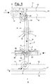
- the transversal path 1 of the spooling unit is defined by the guides 2 that are a distance apart corresponding to the diameter of the neck 3 of the spool carrier 4 that transports the spool 5.
- Said spool 5 is wound on a cop 6 that has an inner diameter such as to allow the pin 7 of the spool carrier 4 to be introduced with a good fit inside its bottom end.
- the transversal path is served by a conveyor belt 8 that transports the spool carriers in the direction of the arrow T and that circulates between two relay rollers 9 with motorised actuation, not shown in the figures for the sake of simplicity.
- the path 11 for the arrival of the new spools on their spool carriers 4 is shown. It consists of two side guides 12, a distance apart that allows the neck 3 of the spool carrier 4 to pass, transported by the conveyor 13 that carries the spool carriers with the new spools in the direction of arrow A.
- the path 15 for discharging the cops 6 of the spent spools again on their spool carriers 4 is shown.
- a stop 18 is arranged for the spool carriers that carry the reserve spools and at the position L for processing the spool that is unwound a stop 19 is arranged for the spool carriers that carry the spools being worked.
- Such stops open to allow one spool carrier to pass at a time and close automatically when the spool carrier has passed.
- the distance between the guides 12 widens, having a transversal cavity that allows the sideways movement and the locking of the spool carrier 4 with its spool, which is illustrated hereafter in greater detail in figure 3 .
- the spooling station is in spool change configuration.
- the stop 19 has opened and closed: the spool carrier with the cop 6 of the spent spool is sent towards the discharge, to be deposited in the conveyor 17.
- the stop 18 has similarly opened and closed: the first spool carrier with the new spool 5 of the reserve is delivered by the conveyor belt 8 into the position L.
- reserve position R there is a single spool carrier: the control unit of the spooling unit commands that a further reserve spool be picked up from the feed circuit 11. This picking up involves the commanding of the actuation of the L-shaped deviator lever 21 by the control unit.
- Such a deviator lever 21, placed at the entry of the transversal path 1, is hinged with a pin 50 and is equipped with two ends 51 and 52.
- the deviator lever 21 intercepts the neck of the arriving spool carrier and deviates it from the conveyor belt 13 to the conveyor 8 with its end 51 that intercepts the path 11 as shown in figure 1 .
- the same deviated spool carrier rests, with its neck 3 on the end 52 of the deviator lever 21 and causes the access to the spooling station to be closed, after the spool carrier with the new spool that goes to constitute the second reserve spool has passed, as shown later on in figure 4 .
- the rotation stroke that the deviator lever L is able to make is defined by two limit switches, not indicated in the figures for the sake of simplicity, at the interception position of the spool carrier arriving on the path 11 and at the closed position of the transversal path 1 inside the spooling unit.
- the path 1 stays closed by the deviator lever 21 until a new spool is needed again by the spooling unit.
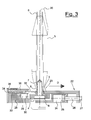
- Figure 3 shows a front view of the section of the transversal path inside the spooling station, when the spool is being changed as illustrated with reference to figures 1 and 2 , and in greater detail on the blocking system of the spool carrier and of the spool being worked.
- the locking members comprise: a slider 22, with a concave end 23 placed at the level of the neck 3 of the spool carrier 4 and configured to rest coherently on it, actuated by a pneumatic cylinder 24, which can be single or double-acting, in which a piston 25 slides, connected to the slider 22 with a stem 26 and a nut 27;
- figures 4 , 5 and 6 illustrate the configuration of the transversal path inside the spooling station, with the spool changed, locked and unwinding.
- figure 4 it is possible to see the spool carrier with the cop 6 of the spent spool now sent onto the conveyor 17.
- the stop 18 has closed and in the reserve position R in which there are now two spool carriers with the reserve spools.
- the deviator lever 21 is closed to prevent access to the spooling station, after the spool carrier with the new spool that has gone to make up the reserve has passed.
- the spool in work position L is unwinding and locked, as better illustrated with reference to figure 5 , in which the spool 5 is shown with unwinding already having begun, so as illustrated in figure 6 .
- the control unit of the spooling station has commanded the locking operations before unwinding again with the new spool 5.
- the locking operations are, for example, the following.
- the slider 22 has been pushed towards the left by pushing its end 23 to rest on the neck 3 of the spool carrier, through actuation of the pneumatic cylinder 24 by injecting pressurised fluid into its right chamber 24D and making the piston 25 and the slider 22 slide according to the arrow S.
- the new spool 5 which was resting on the conveyor belt 8 and ready for locking, is moved sideways, with respect to the path 1, and detached from the conveyor belt 8.
- the base disc of the spool carrier 4 between its bottom surface 30 and the nib 31 is thus pushed into the cavity 29.
- the neck 3 of the spool carrier itself rests against the rod 32 and pushes it in a guide 33 and compression loading the contrast spring 34, thus locking the spool carrier 4 between the slider 22 and the rod 32.
- the spool 5 is also pushed towards the left.
- the slider 36 receives the spool with its end 27 on which the cop 6 rests, sliding towards the left counteracted by the contrast spring 38, which is also compression-loaded.
- the spool is then locked by resting it elastically against the pin 7 of the spool carrier 4, in turn locked.
- Such a locking system by sideways movement of the spool carrier 4 with the spool 5, allows the base of the spool carrier and, in particular, its central opening 41 that opens out into the bottom face of its base disc and that communicates with the orifice 42 arranged on the top of the pin 7 to be freed.
- a compressed air injector nozzle 45 is arranged aiming upwards, placed in a position misaligned with respect to the conveyor belt 8 and centred from the bottom with respect to the blocked position of the spool carrier 4.
- the central opening 41 can thus be engaged by the nozzle 45 below that can inject a jet of compressed air inside the cop 6 to withdraw the end 20 of the spool 6 and use it to start the unwinding of the spool itself.
- the unblocking operations are, for example, the previous ones in reverse.
- the thrusting of the slider 22 is stopped, through release of the fluid injected into the right chamber 24D of the pneumatic cylinder 24, allowing the piston 25 and the slider 22 to slide according to the arrow D, through the effect of the pushing of the spring 34, previously loaded by the action of the slider 22 itself.
- the spool carrier 4 which carries the cop 6 of the spent spool, is moved towards the right and is thus taken back onto the conveyor belt 8, and is ready to be discharged.
- the device for processing spools according to the present invention offers substantial advantages, of which the following deserve to at least be pointed out.
- the spool being worked is unwound at high speeds, of the order of 30 m/sec, and with a balloon that rotates like a vortex: it is thus subjected to discontinuous actions that tend to pull out its cop 6 from the pin 7 of the spool carrier 4, if the spool is not locked well.
- the yarn being unwound is subjected to a centrifugal effect from which a substantial tension derives: the rigid lockings can cause the yarn to pull away.
- the locking requirements are particularly needed with hairy yarns, fantasy yarns and with irregularly wound yarns.
- the technical solution foreseen with the present invention foresees to firstly lock the spool carrier, so as to ensure that its pin 7 and its neck 3 are in a constant and predetermined position.
- the spool is then locked by pushing its cop 6 against the pin 7.
- the two lockings are carried out in series with the interposition of elastic elements that are able to ensure the damping of possible vibration stresses.
- the direction of the axis of the pin 7 is in any case rigidly fixed by the interlocking action of the edge of the base disc of the spool carrier in the cavity 29 so as to keep the rotary trajectories of the yarn constant during the unwinding of the spool.
- the locking action of the spool 5 being unwound is associated with the sideways movement of the spool carrier freeing the bottom face of its base and the opening 41 by the air jet to pull away the end 20.
Landscapes
- Replacing, Conveying, And Pick-Finding For Filamentary Materials (AREA)
- Wire Processing (AREA)
- Transplanting Machines (AREA)
- Soil Working Implements (AREA)
- Branching, Merging, And Special Transfer Between Conveyors (AREA)
- Intermediate Stations On Conveyors (AREA)
Applications Claiming Priority (1)
| Application Number | Priority Date | Filing Date | Title |
|---|---|---|---|
| ITMI20070134 ITMI20070134A1 (it) | 2007-01-29 | 2007-01-29 | Stazione di roccatura automatica |
Publications (3)
| Publication Number | Publication Date |
|---|---|
| EP1950163A2 true EP1950163A2 (fr) | 2008-07-30 |
| EP1950163A3 EP1950163A3 (fr) | 2009-04-01 |
| EP1950163B1 EP1950163B1 (fr) | 2011-09-07 |
Family
ID=39325858
Family Applications (1)
| Application Number | Title | Priority Date | Filing Date |
|---|---|---|---|
| EP20080100804 Active EP1950163B1 (fr) | 2007-01-29 | 2008-01-23 | Tête de bobinage automatique |
Country Status (3)
| Country | Link |
|---|---|
| EP (1) | EP1950163B1 (fr) |
| CN (1) | CN101234718B (fr) |
| IT (1) | ITMI20070134A1 (fr) |
Cited By (2)
| Publication number | Priority date | Publication date | Assignee | Title |
|---|---|---|---|---|
| CN115924623A (zh) * | 2022-11-27 | 2023-04-07 | 董旭伟 | 一种可伸缩锁紧的多用焊锡丝座 |
| IT202100031307A1 (it) * | 2021-12-14 | 2023-06-14 | Savio Macch Tessili Spa | Unità di roccatura con spintore di bloccaggio tubetto e spintore di centratura piattello perfezionati e relativo metodo di controllo |
Families Citing this family (4)
| Publication number | Priority date | Publication date | Assignee | Title |
|---|---|---|---|---|
| CN109019172B (zh) * | 2018-08-31 | 2024-06-04 | 杭州锐冠科技有限公司 | 一种可自动抓纱的络筒机 |
| CN109019171B (zh) * | 2018-08-31 | 2024-06-04 | 杭州锐冠科技有限公司 | 一种用于络筒机的自动抓纱装置 |
| CN110127451B (zh) * | 2019-05-29 | 2021-06-22 | 陈金秋 | 一种打线机的线调试机构 |
| CN110240002B (zh) * | 2019-07-16 | 2021-03-12 | 江西博能上饶线材有限公司 | 一种漆包线生产用放线装置 |
Citations (4)
| Publication number | Priority date | Publication date | Assignee | Title |
|---|---|---|---|---|
| EP0374403A1 (fr) | 1988-12-23 | 1990-06-27 | W. SCHLAFHORST AG & CO. | Dispositif pour saisir pneumatiquement et dévider à la défilée le bout de fil d'une canette |
| US4953798A (en) | 1988-03-17 | 1990-09-04 | Murata Kikai Kabushiki Kaisha | Winding unit |
| EP0402630A2 (fr) | 1989-06-15 | 1990-12-19 | W. SCHLAFHORST AG & CO. | Bobinoir automatique avec un système de transport de canettes et de tubes avec plusieurs boucles de transport |
| US5484115A (en) | 1993-11-11 | 1996-01-16 | W. Schlafhorst Ag & Co. | Textile machine having multiple winding stations for producing wound yarn packages |
Family Cites Families (4)
| Publication number | Priority date | Publication date | Assignee | Title |
|---|---|---|---|---|
| JPS6023260A (ja) * | 1983-07-19 | 1985-02-05 | Murata Mach Ltd | 糸端の口出し装置 |
| JPS6061471A (ja) * | 1983-09-14 | 1985-04-09 | Murata Mach Ltd | ワインダにおけるボビン供給・排出システム |
| JPH0336171A (ja) * | 1989-06-30 | 1991-02-15 | Murata Mach Ltd | ワインダ |
| JPH1059622A (ja) * | 1996-08-20 | 1998-03-03 | Murata Mach Ltd | ボビン搬送用トレイ清掃装置 |
-
2007
- 2007-01-29 IT ITMI20070134 patent/ITMI20070134A1/it unknown
-
2008
- 2008-01-23 EP EP20080100804 patent/EP1950163B1/fr active Active
- 2008-01-28 CN CN 200810003246 patent/CN101234718B/zh not_active Expired - Fee Related
Patent Citations (5)
| Publication number | Priority date | Publication date | Assignee | Title |
|---|---|---|---|---|
| US4953798A (en) | 1988-03-17 | 1990-09-04 | Murata Kikai Kabushiki Kaisha | Winding unit |
| EP0374403A1 (fr) | 1988-12-23 | 1990-06-27 | W. SCHLAFHORST AG & CO. | Dispositif pour saisir pneumatiquement et dévider à la défilée le bout de fil d'une canette |
| EP0374404A1 (fr) | 1988-12-23 | 1990-06-27 | W. SCHLAFHORST AG & CO. | Dispositif d'alimentation en fil pour bobinoir automatique |
| EP0402630A2 (fr) | 1989-06-15 | 1990-12-19 | W. SCHLAFHORST AG & CO. | Bobinoir automatique avec un système de transport de canettes et de tubes avec plusieurs boucles de transport |
| US5484115A (en) | 1993-11-11 | 1996-01-16 | W. Schlafhorst Ag & Co. | Textile machine having multiple winding stations for producing wound yarn packages |
Cited By (3)
| Publication number | Priority date | Publication date | Assignee | Title |
|---|---|---|---|---|
| IT202100031307A1 (it) * | 2021-12-14 | 2023-06-14 | Savio Macch Tessili Spa | Unità di roccatura con spintore di bloccaggio tubetto e spintore di centratura piattello perfezionati e relativo metodo di controllo |
| EP4197950A1 (fr) * | 2021-12-14 | 2023-06-21 | Savio Macchine Tessili S.p.A. | Unité d'enroulement avec poussoir de verrouillage de tube et poussoir de centrage de plaque améliorés et procédé de commande associé |
| CN115924623A (zh) * | 2022-11-27 | 2023-04-07 | 董旭伟 | 一种可伸缩锁紧的多用焊锡丝座 |
Also Published As
| Publication number | Publication date |
|---|---|
| ITMI20070134A1 (it) | 2008-07-30 |
| CN101234718A (zh) | 2008-08-06 |
| EP1950163A3 (fr) | 2009-04-01 |
| EP1950163B1 (fr) | 2011-09-07 |
| CN101234718B (zh) | 2013-01-16 |
Similar Documents
| Publication | Publication Date | Title |
|---|---|---|
| EP1950163B1 (fr) | Tête de bobinage automatique | |
| US3295775A (en) | Method and apparatus for readying the winding operation of yarn supply coils on coil winding machines | |
| CN101583551A (zh) | 用于卷绕长丝的装置 | |
| US3774859A (en) | Bobbin handling system | |
| CN101596990B (zh) | 吸嘴 | |
| KR20060111548A (ko) | 피복탄성체방사의 생산과 급송스풀의 자동교체방법 및디바이스 | |
| US4856270A (en) | Automated textile thread processing system | |
| US3544018A (en) | Bobbin handling | |
| EP0690018B1 (fr) | Bobinoir à tourelle | |
| US4616789A (en) | Yarn end readying device in winder | |
| US3474975A (en) | Bobbin handling installation | |
| JPH05155424A (ja) | コップ供給ステーション | |
| US5791575A (en) | System for handling and distributing spools for an automatic coning machine | |
| US6098914A (en) | System for moving spools and tubes in automatic spoolers | |
| ITMI981819A1 (it) | Dispositivo caricatore di spole su un supporto a piattello per il loro trasporto e posizionamento nelle macchine tessili | |
| CN110462117B (zh) | 熔纺装置 | |
| EP1932793B1 (fr) | Dispositif et procédé de préparation de bobines pour alimenter un bobinoir automatique | |
| US5683046A (en) | System for positioning spools at a coning unit of an automatic coning machine | |
| US4597540A (en) | Bobbin supplying device in automatic winder | |
| CN104671000A (zh) | 筒管保持装置、筒管设置装置及纱线卷绕机 | |
| EP0721911A1 (fr) | Dispositif pour la manipulation automatique de bobines dans une machine automatique de bobinage de bobines coniques | |
| JPS6052217B2 (ja) | 精紡ワインダの風綿除去システム | |
| US6315236B1 (en) | Apparatus and method for guiding and cutting an advancing yarn during a package doff | |
| US20010004999A1 (en) | Interface in the transport system of a textile machine producing cross-wound bobbins | |
| US5423493A (en) | Method for operating an automatic bobbin-winding machine during batch changing operations |
Legal Events
| Date | Code | Title | Description |
|---|---|---|---|
| PUAI | Public reference made under article 153(3) epc to a published international application that has entered the european phase |
Free format text: ORIGINAL CODE: 0009012 |
|
| AK | Designated contracting states |
Kind code of ref document: A2 Designated state(s): AT BE BG CH CY CZ DE DK EE ES FI FR GB GR HR HU IE IS IT LI LT LU LV MC MT NL NO PL PT RO SE SI SK TR |
|
| AX | Request for extension of the european patent |
Extension state: AL BA MK RS |
|
| PUAL | Search report despatched |
Free format text: ORIGINAL CODE: 0009013 |
|
| AK | Designated contracting states |
Kind code of ref document: A3 Designated state(s): AT BE BG CH CY CZ DE DK EE ES FI FR GB GR HR HU IE IS IT LI LT LU LV MC MT NL NO PL PT RO SE SI SK TR |
|
| AX | Request for extension of the european patent |
Extension state: AL BA MK RS |
|
| 17P | Request for examination filed |
Effective date: 20090922 |
|
| AKX | Designation fees paid |
Designated state(s): CH DE IT LI TR |
|
| 17Q | First examination report despatched |
Effective date: 20091202 |
|
| GRAP | Despatch of communication of intention to grant a patent |
Free format text: ORIGINAL CODE: EPIDOSNIGR1 |
|
| GRAS | Grant fee paid |
Free format text: ORIGINAL CODE: EPIDOSNIGR3 |
|
| GRAA | (expected) grant |
Free format text: ORIGINAL CODE: 0009210 |
|
| REG | Reference to a national code |
Ref country code: CH Ref legal event code: EP |
|
| REG | Reference to a national code |
Ref country code: DE Ref legal event code: R096 Ref document number: 602008009469 Country of ref document: DE Effective date: 20111201 |
|
| REG | Reference to a national code |
Ref country code: CH Ref legal event code: NV Representative=s name: PATENTANWAELTE SCHAAD, BALASS, MENZL & PARTNER AG |
|
| PLBE | No opposition filed within time limit |
Free format text: ORIGINAL CODE: 0009261 |
|
| STAA | Information on the status of an ep patent application or granted ep patent |
Free format text: STATUS: NO OPPOSITION FILED WITHIN TIME LIMIT |
|
| RAP2 | Party data changed (patent owner data changed or rights of a patent transferred) |
Owner name: PENELOPE S.P.A. |
|
| 26N | No opposition filed |
Effective date: 20120611 |
|
| REG | Reference to a national code |
Ref country code: DE Ref legal event code: R097 Ref document number: 602008009469 Country of ref document: DE Effective date: 20120611 |
|
| RAP2 | Party data changed (patent owner data changed or rights of a patent transferred) |
Owner name: SAVIO MACCHINE TESSILI S.P.A. |
|
| PGFP | Annual fee paid to national office [announced via postgrant information from national office to epo] |
Ref country code: DE Payment date: 20200131 Year of fee payment: 13 |
|
| PGFP | Annual fee paid to national office [announced via postgrant information from national office to epo] |
Ref country code: CH Payment date: 20210120 Year of fee payment: 14 |
|
| REG | Reference to a national code |
Ref country code: DE Ref legal event code: R119 Ref document number: 602008009469 Country of ref document: DE |
|
| PG25 | Lapsed in a contracting state [announced via postgrant information from national office to epo] |
Ref country code: DE Free format text: LAPSE BECAUSE OF NON-PAYMENT OF DUE FEES Effective date: 20210803 |
|
| PGFP | Annual fee paid to national office [announced via postgrant information from national office to epo] |
Ref country code: TR Payment date: 20220124 Year of fee payment: 15 Ref country code: IT Payment date: 20220105 Year of fee payment: 15 |
|
| REG | Reference to a national code |
Ref country code: CH Ref legal event code: PL |
|
| PG25 | Lapsed in a contracting state [announced via postgrant information from national office to epo] |
Ref country code: LI Free format text: LAPSE BECAUSE OF NON-PAYMENT OF DUE FEES Effective date: 20220131 Ref country code: CH Free format text: LAPSE BECAUSE OF NON-PAYMENT OF DUE FEES Effective date: 20220131 |
|
| PG25 | Lapsed in a contracting state [announced via postgrant information from national office to epo] |
Ref country code: IT Free format text: LAPSE BECAUSE OF NON-PAYMENT OF DUE FEES Effective date: 20230123 |