EP1955771A2 - Bloc de régulation de la température doté de dispositifs de régulation de la température - Google Patents
Bloc de régulation de la température doté de dispositifs de régulation de la température Download PDFInfo
- Publication number
- EP1955771A2 EP1955771A2 EP08009247A EP08009247A EP1955771A2 EP 1955771 A2 EP1955771 A2 EP 1955771A2 EP 08009247 A EP08009247 A EP 08009247A EP 08009247 A EP08009247 A EP 08009247A EP 1955771 A2 EP1955771 A2 EP 1955771A2
- Authority
- EP
- European Patent Office
- Prior art keywords
- tempering
- block
- temperature
- temperierblock
- receptacles
- Prior art date
- Legal status (The legal status is an assumption and is not a legal conclusion. Google has not performed a legal analysis and makes no representation as to the accuracy of the status listed.)
- Withdrawn
Links
Images


Classifications
-
- B—PERFORMING OPERATIONS; TRANSPORTING
- B01—PHYSICAL OR CHEMICAL PROCESSES OR APPARATUS IN GENERAL
- B01L—CHEMICAL OR PHYSICAL LABORATORY APPARATUS FOR GENERAL USE
- B01L3/00—Containers or dishes for laboratory use, e.g. laboratory glassware; Droppers
- B01L3/50—Containers for the purpose of retaining a material to be analysed, e.g. test tubes
- B01L3/508—Rigid containers without fluid transport within
- B01L3/5085—Rigid containers without fluid transport within for multiple samples, e.g. microtitration plates
- B01L3/50851—Rigid containers without fluid transport within for multiple samples, e.g. microtitration plates specially adapted for heating or cooling samples
-
- B—PERFORMING OPERATIONS; TRANSPORTING
- B01—PHYSICAL OR CHEMICAL PROCESSES OR APPARATUS IN GENERAL
- B01L—CHEMICAL OR PHYSICAL LABORATORY APPARATUS FOR GENERAL USE
- B01L3/00—Containers or dishes for laboratory use, e.g. laboratory glassware; Droppers
- B01L3/50—Containers for the purpose of retaining a material to be analysed, e.g. test tubes
- B01L3/508—Rigid containers without fluid transport within
- B01L3/5085—Rigid containers without fluid transport within for multiple samples, e.g. microtitration plates
- B01L3/50853—Rigid containers without fluid transport within for multiple samples, e.g. microtitration plates with covers or lids
-
- B—PERFORMING OPERATIONS; TRANSPORTING
- B01—PHYSICAL OR CHEMICAL PROCESSES OR APPARATUS IN GENERAL
- B01L—CHEMICAL OR PHYSICAL LABORATORY APPARATUS FOR GENERAL USE
- B01L7/00—Heating or cooling apparatus; Heat insulating devices
- B01L7/52—Heating or cooling apparatus; Heat insulating devices with provision for submitting samples to a predetermined sequence of different temperatures, e.g. for treating nucleic acid samples
-
- B—PERFORMING OPERATIONS; TRANSPORTING
- B01—PHYSICAL OR CHEMICAL PROCESSES OR APPARATUS IN GENERAL
- B01L—CHEMICAL OR PHYSICAL LABORATORY APPARATUS FOR GENERAL USE
- B01L7/00—Heating or cooling apparatus; Heat insulating devices
- B01L7/52—Heating or cooling apparatus; Heat insulating devices with provision for submitting samples to a predetermined sequence of different temperatures, e.g. for treating nucleic acid samples
- B01L7/525—Heating or cooling apparatus; Heat insulating devices with provision for submitting samples to a predetermined sequence of different temperatures, e.g. for treating nucleic acid samples with physical movement of samples between temperature zones
-
- B—PERFORMING OPERATIONS; TRANSPORTING
- B01—PHYSICAL OR CHEMICAL PROCESSES OR APPARATUS IN GENERAL
- B01L—CHEMICAL OR PHYSICAL LABORATORY APPARATUS FOR GENERAL USE
- B01L7/00—Heating or cooling apparatus; Heat insulating devices
- B01L7/52—Heating or cooling apparatus; Heat insulating devices with provision for submitting samples to a predetermined sequence of different temperatures, e.g. for treating nucleic acid samples
- B01L7/525—Heating or cooling apparatus; Heat insulating devices with provision for submitting samples to a predetermined sequence of different temperatures, e.g. for treating nucleic acid samples with physical movement of samples between temperature zones
- B01L7/5255—Heating or cooling apparatus; Heat insulating devices with provision for submitting samples to a predetermined sequence of different temperatures, e.g. for treating nucleic acid samples with physical movement of samples between temperature zones by moving sample containers
-
- B—PERFORMING OPERATIONS; TRANSPORTING
- B01—PHYSICAL OR CHEMICAL PROCESSES OR APPARATUS IN GENERAL
- B01L—CHEMICAL OR PHYSICAL LABORATORY APPARATUS FOR GENERAL USE
- B01L7/00—Heating or cooling apparatus; Heat insulating devices
- B01L7/54—Heating or cooling apparatus; Heat insulating devices using spatial temperature gradients
-
- B—PERFORMING OPERATIONS; TRANSPORTING
- B01—PHYSICAL OR CHEMICAL PROCESSES OR APPARATUS IN GENERAL
- B01L—CHEMICAL OR PHYSICAL LABORATORY APPARATUS FOR GENERAL USE
- B01L2200/00—Solutions for specific problems relating to chemical or physical laboratory apparatus
- B01L2200/02—Adapting objects or devices to another
- B01L2200/023—Adapting objects or devices to another adapted for different sizes of tubes, tips or container
-
- B—PERFORMING OPERATIONS; TRANSPORTING
- B01—PHYSICAL OR CHEMICAL PROCESSES OR APPARATUS IN GENERAL
- B01L—CHEMICAL OR PHYSICAL LABORATORY APPARATUS FOR GENERAL USE
- B01L2300/00—Additional constructional details
- B01L2300/18—Means for temperature control
- B01L2300/1805—Conductive heating, heat from thermostatted solids is conducted to receptacles, e.g. heating plates, blocks
- B01L2300/1822—Conductive heating, heat from thermostatted solids is conducted to receptacles, e.g. heating plates, blocks using Peltier elements
-
- G—PHYSICS
- G01—MEASURING; TESTING
- G01N—INVESTIGATING OR ANALYSING MATERIALS BY DETERMINING THEIR CHEMICAL OR PHYSICAL PROPERTIES
- G01N35/00—Automatic analysis not limited to methods or materials provided for in any single one of groups G01N1/00 - G01N33/00; Handling materials therefor
- G01N2035/00346—Heating or cooling arrangements
- G01N2035/00356—Holding samples at elevated temperature (incubation)
- G01N2035/00366—Several different temperatures used
Definitions
- the invention relates to a tempering of the type mentioned in the preamble of claim 1.
- Such tempering is from the U.S. Patent 5,525,300 known.
- Two tempering devices acting on thermal contact at opposite ends of the tempering block heat the tempering block from one end and cool it from the other end. It flows a heat flow in the longitudinal direction between the tempering through the Temperierblock and there is a temperature profile in the longitudinal direction over the Temperierblock, which leads to different temperatures.
- With such a tempering block generating a temperature gradient it is possible, for example, to determine the optimum temperature for a temperature step of the PCR process in the PCR process.
- a disadvantage of the known construction is the temperature of the tempering only from its ends. When switching on the device or when changing the temperature level to be set in the temperature control block due to the temperature control from the ends longer tempering until the desired equilibrium is set. Furthermore, the temperature may deviate from the desired temperature profile in the middle region of the tempering block due to environmental influences.
- the object of the present invention is therefore to provide a Tempelierblock the generic type in which the desired temperature profile is faster and trouble-free adjustable.
- the plurality of tempering devices acting on the tempering block are contacted over a large area with adjoining fields of the contacting side.
- a temperature gradient can be adjusted.
- the known terminal arrangement of the tempering is not necessary for this purpose. This results in the advantage of a direct temperature influencing of the tempering block over its entire surface. Environmental influences, e.g. through the surrounding air, are largely switched off.
- the large-area contact with temperature devices can be used in an alternative mode very easy for uniform temperature control of all recordings. It is not necessary, as in the construction mentioned above, in addition to the heating and cooling terminally arranged tempering provide an additional, arranged on the Kunststoffierseite tempering.
- the features of claim 2 are provided. This makes it possible to reduce the heat flow flowing in the tempering between adjacent tempering. By this heat flow conditional influences between the temperature control means controlling control devices that can lead to control oscillations are thereby reduced, so that it is possible to simplify the electronic control effort.
- the temperature profile over the tempering block ie the respective temperature gradient, does not always correspond to the desired temperature profile. Deviations occur in particular at the ends of the tempering block, in which the influence of adjacent tempering devices decreases and thus the temperature gradient flattens out.
- the features of claim 3 are provided. With such sections other thermal resistance, the temperature curve can be corrected. In particular, can be achieved by increasing the thermal resistance, a higher temperature gradient, so that the flats can be corrected at the ends of the temperature curve.
- the sections are formed from the middle of the tempering block to its edge with increasing thermal resistance.
- the generated temperature profile can be linearized.
- the sections according to claim 5 are advantageously formed as grooves, which result in an increased thermal resistance by simple weakening of the cross section. Compared with the known for this purpose from the generic generic construction mentioned cross bores results in the advantage of easier manufacturability and cheaper arrangement between trained as wells shots.
- the features of claim 6 are provided.
- Distributed in the area arranged tempering can be operated in different ways. It can laterally adjacent tempering be operated equal tempering, so that the tempering in the longitudinal direction or transverse direction has a temperature gradient.
- a gradient can be set in succession at different temperature levels in different directions in a tempering block.
- the tempering devices can also all be operated differently, so that a temperature gradient is set both in the x-direction and in the y-direction is, for. B. with different temperature gradients in the two directions.
- the features of claim 7 are provided. This makes it possible to use two different types of vessels occurring in the laboratory mode without retooling the laboratory thermostat. A mixed assembly is possible.
- the large number of closely spaced, designed as wells recordings reduces the mass of the tempering. This reduces the heat capacity of the tempering block so that it can be brought faster to desired temperatures.
- the recordings of a type of a predetermined grid arrangement of vessels are advantageously adapted.
- vessels which are e.g.
- the containers are successively brought into engagement with different, differently tempered tempering blocks which either have a temperature gradient or else a constant temperature over their surface.
- the Temperierblöcke can be arranged for lateral movement in a laterally displaceable carriage.
- they can also be arranged in a rotor which, for example, rotates in a plane parallel to the holder like a carousel.
- they are rotated by a rotor about an axis lying parallel to the holder, which allows a particularly space-saving arrangement.
- the blocks can be moved to the distance movement relative to the rotor or preferably the rotor is moved to the distance movement as a whole.
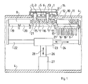
- Fig.1 shows a laboratory thermostat, which is particularly suitable for the PCR process.
- Reaction mixtures should be successively brought to different temperatures.
- the sample liquids are provided in containers 1, which are formed in the illustrated embodiment as commercially available reaction vessels made of thin-walled plastic material. They have a cylindrical area which, like Fig. 1 shows, in its lower, the sample liquid receiving end portion, tapers conically. The upper edge has a collar 2 and a container 1 closing, elastically deformable lid. 3
- the laboratory thermostat shown has an enclosing housing 4, in the top of which a holder 5 formed as a perforated plate is arranged, with holes 6 which hold the containers 1 in position and secure against their collars 2 against falling out.
- a tempering 7 is arranged, which has receptacles 11 in the form of depressions on its upper receiving side 10, which correspond in shape to the shape of the lower end portions of the container 1.
- the arrangement of the receptacles 11 in the surface of the receiving side 10 of the block 7 corresponds to the arrangement of the holes 6 in the holder 5.
- a cover this cover plate 12 is disposed above the holder 5, which presses on the elastic cover 3 of the container 1.
- the cover plate 12 is brought to an appropriate tempering device 13, for example a Peltier element with Anschlußteitern 14 at a suitable temperature.
- the block 7 is at its receiving side 10 opposite Kunststoffierseite 15 in contact with a tempering device 16.
- a Peltier element is particularly suitable for this purpose, since it can be used as required for heating or cooling.
- the block 7 can be brought to a desired temperature.
- a temperature sensor is provided which controls the temperature control means 16 via an electronic control device in such a way that the temperature in the block 7 is kept constant at a suitable level.
- the sample liquid takes in the containers very quickly and with high precision, the temperature of the block 7, so the desired reaction temperature.
- the Temperierblöcke 8 and 9 are also provided with tempering, in the case of the block 9 with a tempering 16 and in the case of Temperierblockes 8 with two juxtaposed tempering 19 and 20, which can be operated in parallel with the same temperature or even is to be explained in more detail, with different temperature.
- the tempering device 16 under the tempering 9 is provided with a heat sink 18, which may also be provided in the other Temperiereimichtept and is advantageous if the tempering is designed as a Peltier element that must give off or absorb heat on its surface facing away from the tempering ,
- the arrangement of the recesses 11 in all three blocks 7, 8 and 9 is identical.
- the blocks can thus be selectively brought into engagement with the containers 1 in the holder 5.
- a block change drive is provided.
- the blocks 7, 8 and 9 are connected to one another with supports 21 rigidly in a plane to a laterally displaceable Schlittenkontrukstrutation, which is mounted longitudinally displaceably with a push rod 22 in a sliding guide 23 in the direction of the arrow 24.
- the side drive for the tempering blocks 7, 8 and 9 formed in this way is height adjustable as a whole with a distance drive.
- the sliding guide 23 is mounted on a push rod 26 which is mounted in a sliding guide 27 in the direction of arrow 28 in a height-displaceable manner.
- the containers I sitting in the holder 5 can be alternately brought into thermal contact with the tempering blocks 7, 8 or 9. These can be kept thermostated at different temperatures.
- the container I can therefore be brought in rapid succession to different high-precision temperatures, which is particularly desirable for PCR purposes.
- the receptacles 11 in the Temperierblöcken 7, 8 and 9, as well as the holes 6 in the holder 5, are arranged in a suitable manner, for example in the form of rows and columns. After removing the cover plate 12, the containers can be replaced. You can, for example, in a labor-saving manner together with the holder 5 are exchanged, which is replaceable provided for this purpose on the housing 4.
- the blocks may also be provided in a different number depending on the desired number of temperature stages in the illustrated linear slide arrangement.
- the blocks can be connected via individual distance drives with a cable drive.
- the drive of the blocks for the purpose of their replacement under the containers 1 can be done by hand or preferably by means of motor drives, for example, computer-controlled in a manner not shown the drive of the Sliding rod 22 relative to their sliding guide 23 and the drive of the push rod 26 relative to their sliding guide 27 get. In this way, a Thermostatticianszyklus can be done programmatically with the desired sequence.
- the side drive can also be designed for example as a carousel drive.
- the illustrated blocks 7, 8 and 9 would be arranged to be pivotable in a plane parallel to the holder 5 about an axis of rotation perpendicular thereto.
- FIG. 2 A further advantageous embodiment of the block change drive is in FIG. 2 shown. Parts of the construction correspond to those of FIG. 1 , For matching parts, the same reference numerals are used as far as possible.
- the holder 5 In the top of a slightly different shaped housing 4 ', the holder 5 is provided for holding vessels 1. It is in turn covered with a cover plate 12, which provides for pressure and temperature control of the vessels from above.
- a cover plate 12 which provides for pressure and temperature control of the vessels from above.
- FIG. 2 releasable latches 29, which are also in Fig. 1 may be provided and secure the cover plate 12 in the position shown.
- the laboratory thermostat shows the three tempering blocks 7, 8 and 9 of the FIG. 1 on and additionally a tempering 9 ', which is formed accordingly.
- These tempering blocks correspond to the embodiment of the Fig. 1 including the associated temperature control.
- the tempering 7 is in its illustrated position in engagement with the vessels 1 in alignment under the holder. 5
- the movement means for the lateral movement of the tempering blocks is designed differently.
- the blocks 7, 8. 9 and 9 ' are mounted in a 90 ° position on a rotor 30, which is held rotatably about an axis 31 in the direction of the arrow 32 in the head 33 of the push rod 26, according to Fig. 1 in the direction of arrow 28 in the sliding guide 27 is longitudinally displaceable.
- the push rod 26 is first moved with the rotor 30 down until the tempering currently in engagement comes out of engagement with the vessels 1. Then, the rotor 30 is rotated by a multiple of 90 ° to bring another tempering block in alignment under the holder 5 and bring by lifting the push rod 26 in contact with the vessels 1.
- motor drives may be provided, which are e.g. be controlled by a computer control to fully automatic process.
- Fig. 3 shows the tempering 8 of the FIGS. 1 and 2 with its two tempering 19 and 20 in side view.
- the receptacles 11 'formed as depressions for receiving the containers are shown here somewhat smaller and in greater numbers.
- the recordings 11 ' can be arranged in rows and columns arranged on the receiving side 10. They serve to accommodate a larger number of containers for their temperature.
- the tempering devices 19 and 20, which rest against the block 8 from the contacting side 15, can preferably be provided as Peltier elements with in Fig. 3 not shown connecting lines for current application. This allows any temperatures to be set to heating or cooling.
- the tempering devices 19 and 20 can also be designed, for example, as liquid-flowed heat exchangers, which are supplied, for example, via hose lines.
- the tempering 19 and 20 can be brought to the same temperature or to different temperatures. Temperature sensors, not shown, in the block above the tempering devices can be connected to a control device controlling the heat supply and removal by the tempering device inlets.
- the tempering 19 and 20 each about half the area of Kunststoffierseite 15 at.
- the good thermal contact can be secured by gluing, screwing or other attachment.
- tempering devices 19 and 20 are brought to different temperatures, wherein in the case shown the tempering device 20 is at a higher temperature, the result is a temperature profile over the length of the tempering block 8 Fig. 3a is shown.
- the tempering device 20 continuously supplies the tempering block 8 with heat, while the tempering device 19 extracts heat from the tempering block. Heat thus flows through the tempering 8 between the tempering 20 and 19th
- Fig. 3a shows, in which the temperature T is shown over the distance S, in the central region of the tempering 8, a linear temperature profile.
- the temperature curve flattens, since toward the left end of the tempering block 8 the heating influence of the tempering device 20 decreases more and more.
- the temperature curve is proportional to the product of heat flow and thermal resistance, can be influenced by local change in the thermal resistance of the shape of the temperature curve and in particular, as the Fig. 3a shows the curve will be linearized.
- the grooves 37 and 38 are different deep, so with different cross-sectional weakening of the block formed.
- the depth and arrangement of the grooves 37 and 38 in Fig. 3 is only for example. The exact depth, location and number of grooves z. B. can be determined in experiments.
- FIG. 3a shows that flattened on the left side of the tempering 8 to its end, the temperature profile.
- this flattening is compensated by providing the grooves 37 and 38.
- the groove 38 formed deeper than the groove 37. since it is closer to the right edge of the block, ie in a region in which the heat flow from the tempering device 20 to the tempering device 19 is less than at the location of the groove 37.
- a higher heat resistance is needed so a deeper groove. If the groove 38 is further deepened, as indicated by dashed lines with 38 ', the temperature profile can be further raised in this area, as in FIG. 3a shown in phantom.
- Fig. 4 shows in representation accordingly Fig. 3 a Temperierblock 48 with three tempering 19 ', 19 and 20. Is heated with the tempering 20 and cooled with the tempering 19', the results in Fig. 4a illustrated temperature curve. Towards the ends of the curve, ie via the tempering devices 19 'and 20, the curve flattens off, since grooves over the temperature control devices, such as the grooves 37 and 38 (FIG. Fig. 3 ) absence.
- the middle tempering device 19 can be operated with a medium temperature or, if necessary, be switched off. It is needed to prevent any deviation of the temperature curve in the middle of the block and is especially needed if the temperature curve as a whole should be moved quickly to another level. Furthermore, it is needed if, alternatively, the entire block is to be brought to the same temperature.
- tempering 19 ', 19 and 20 are each controlled in a separate control circuit via temperature sensors, not shown, which are provided in the block 48 above the individual tempering. Between the control circuits, heat exchange takes place by heat flow in the block between the Temperiereimichtonne. This leads to interactions of the control circuits, which can cause difficult to control control oscillations.
- the grooves 39 can also, as shown in dashed lines with the groove 39 ', from above, ie in the Aufnaluneeite 10, be introduced. Also the grooves 37 and 38 of Fig. 3 may alternatively be introduced into the block from above, ie from the receiving side 10.
- grooves 37, 38 and 39 are shown, which are to hinder the heat flow through the tempering block for different purposes, by weakening the cross-section of the block and thus reduce the thermal conductivity or increase the thermal resistance at this point.
- other possibilities can be used to locally change the thermal conductivity of the block.
- sections in the tempering block which have a different thermal conductivity or a different thermal resistance than the other points of the block can also be provided in another way. Such sections may, for. B. be created by the fact that the block is separated at this point and an intermediate layer of a material higher resistance is used. The above sections can as well as those in the FIGS.
- FIGS. 3 and 4 shown grooves in any lines through the block, but preferably transversely to the heat flow in a straight line between two edges of the block. So run preferably in the FIGS. 3 and 4 shown grooves across the block 8 and 48, that is perpendicular to the plane through the entire block.
- the in the FIGS. 3 and 4 illustrated tempering 8 and 48 is provided with two tempering 19 and 20 or three tempering 19 ', 19 and 20, each extending over the entire width of the block.
- a temperature gradient can in this block so only how the temperature curves of the FIGS. 3a and 4a show, in the longitudinal direction, ie in the drawing from left to right, can be adjusted.
- Fig. 5 shows a variant of a Temperierblockes 58.
- the Kunststoffierseite 15 with field boundaries 61 and 62 in four quadrant fields with tempering devices 59, 60, 59 'and 60' are occupied.
- the tempering block 58 results Temperature gradient in the direction of the x-axis. If the tempering devices 59 and 60 are operated at the same temperature and also the temperature control devices 59 and 60 'are at the same temperature, a temperature gradient results in the vertical direction, ie in the y direction. If all tempering devices are operated at the same temperature, the result is a constant temperature over the entire tempering block 58.
- tempering block 58 is operated successively at two different temperature levels, for example at a temperature level of 30 ° and at a temperature level of 60 °. For both temperature levels, the exact optimum temperature should be determined. This can be done in a Druchlauf, first the Temperierblock is operated at the level of 30 ° in the x direction with a gradient of the temperatures on the tempering of, for example, 28 °. 29 °, 30 °, 31 °, 32 ° generated.
- the Temperierblock is brought to the temperature level 60 ° with a temperature gradient in the y direction, wherein dan in the y direction different temperatures of z. B. 58 °, 59 °, 60 °, 61 °, 62 ° are generated. If the tempering block is equipped with samples to be tempered over its surface in regular rows (x-direction) and columns (y-direction), then these can be evaluated and determined which of these samples were optimally tempered. These had the optimum temperature at both tempering levels.
- a complex temperature field can be set with different temperatures both in the x-direction and in the y-direction. For example, a larger temperature gradient can be set in the x-direction and a smaller temperature gradient in the y-direction. If receptacles for vessels in rows (x-direction) and columns (y-direction) are provided on the receiving side of tempering block 58, then, for example, temperature differences of 1 ° can be set between the rows and temperature differences of 1/10 ° within the rows between the columns become. It can be used to set temperature differences of, for example, 10 ° with a resolution of 1/10 °.
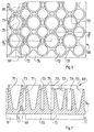
- FIGS. 6 and 7 show in plan view of the receiving side and in section a Temperierblock 68.
- Temperierblock 8 In its basic structure corresponds to the already described Temperierblock 8, which is thus contacted with two tempering 19 and 20 of its Kunststoffierseite 15 ago.
- the two types of receptacles 71 and 72 are arranged in a rectangular grid nested such that in each case between four receptacles 71 of the first type is a receptacle 72 of the second type and vice versa.
- Fig. 7 shows, this results in a filigree block construction with very much weakened cross-section in the upper area of the block, ie towards its receiving side.
- oval holes 73 are still inserted between the receptacles 71 and 72, which lie in the middle between two larger shots 71 and two smaller shots 72, like the Fig. 6 shows.
- the tempering block 70 is additionally weakened in its upper region. Heat conduction between the tempering 20 and 19 is thus less in its upper, weakened by the recordings 71. 72 and the holes 73 thickness range instead, but in the lower, continuous plate 74. the continuous among all recordings 71, 72 and the holes 73 runs.
- the volume of the tempering block 68 is very largely reduced, in particular in its upper, the Kunststoffierseite 15 facing away thick area.
- the heat capacity of the tempering block is greatly reduced.
- FIG. 1 or 2 shown laboratory thermostats the ability to operate in one of the temperature control blocks shown several temperature levels in succession.
- adjacent temperature levels can be operated in a tempering, warning is used for a farther temperature level another tempering.
- three temperature levels for the PCR process z For example, two of the temperature levels can be operated in one block and one in a second block.
- Helpful is also the in the figures shown large-area contacting of the tempering with the tempering, which is a very rapid heating or cooling useful.
- the in the FIGS. 6 and 7 but shown also provides a low thermal conductivity or a high thermal resistance of the tempering in the direction of heat transfer between the tempering 20 and 19.
- a desired temperature profile or a temperature gradient as for example in the FIGS. 3a and 4a is shown, only a small heat flow is required in view of the high pulpieitwiderstandes.
- the temperature control devices 19 and 20 can therefore be designed with low power.
- the in the FIGS. 6 and 7 illustrated tempering 68 has a groove 69 which on the hand of the Fig. 4 explained function of the thermal decoupling between the tempering 20 and 19 met.
- the groove 69 is how Fig. 7 shows in section, stepped in order to reach as deep as possible between the receptacles 71, 72 and the holes 73, but without touching them.
- Fig. 6 (Dashed) shows, the groove 69 is meandering for this purpose between the recesses and holes arranged to wind through.
- the illustrated tempering block 68 may be molded or manufactured using a numerically controlled milling machine, such as aluminum.
- the groove 69 from the receiving side ie in FIG. 7 be introduced from above into the tempering 68. It can, for example, extend transversely through the depressions 71, 72 and holes 73 or even meander-shaped these may be formed circumferentially, for example as a very narrow and deep slot.
Landscapes
- Health & Medical Sciences (AREA)
- Chemical & Material Sciences (AREA)
- Clinical Laboratory Science (AREA)
- Chemical Kinetics & Catalysis (AREA)
- General Health & Medical Sciences (AREA)
- Life Sciences & Earth Sciences (AREA)
- Biochemistry (AREA)
- Molecular Biology (AREA)
- Analytical Chemistry (AREA)
- Hematology (AREA)
- Automatic Analysis And Handling Materials Therefor (AREA)
- Control Of Temperature (AREA)
- Devices For Use In Laboratory Experiments (AREA)
- Apparatus Associated With Microorganisms And Enzymes (AREA)
- Measuring Or Testing Involving Enzymes Or Micro-Organisms (AREA)
- Resistance Heating (AREA)
- Coupling Device And Connection With Printed Circuit (AREA)
- Mounting, Exchange, And Manufacturing Of Dies (AREA)
Applications Claiming Priority (3)
| Application Number | Priority Date | Filing Date | Title |
|---|---|---|---|
| DE1996146115 DE19646115C2 (de) | 1996-11-08 | 1996-11-08 | Verwendung von Temperiereinrichtungen zur Temperierung eines Temperierblockes |
| EP97948904A EP0881950B1 (fr) | 1996-11-08 | 1997-11-07 | Bloc de regulation de temperature dote de dispositifs de regulation de temperature |
| EP04005263.1A EP1426110B1 (fr) | 1996-11-08 | 1997-11-07 | Bloc de régulation de température doté de dispositifs de régulation de température et procédé d'utilisation |
Related Parent Applications (4)
| Application Number | Title | Priority Date | Filing Date |
|---|---|---|---|
| EP04005263.1A Division EP1426110B1 (fr) | 1996-11-08 | 1997-11-07 | Bloc de régulation de température doté de dispositifs de régulation de température et procédé d'utilisation |
| EP04005263.1A Division-Into EP1426110B1 (fr) | 1996-11-08 | 1997-11-07 | Bloc de régulation de température doté de dispositifs de régulation de température et procédé d'utilisation |
| EP97948904.4 Division | 1998-05-22 | ||
| EP04005263.1 Division | 2004-03-05 |
Publications (2)
| Publication Number | Publication Date |
|---|---|
| EP1955771A2 true EP1955771A2 (fr) | 2008-08-13 |
| EP1955771A3 EP1955771A3 (fr) | 2011-02-16 |
Family
ID=7811051
Family Applications (3)
| Application Number | Title | Priority Date | Filing Date |
|---|---|---|---|
| EP08009247A Withdrawn EP1955771A3 (fr) | 1996-11-08 | 1997-11-07 | Bloc de régulation de la température doté de dispositifs de régulation de la température |
| EP97948904A Revoked EP0881950B1 (fr) | 1996-11-08 | 1997-11-07 | Bloc de regulation de temperature dote de dispositifs de regulation de temperature |
| EP04005263.1A Expired - Lifetime EP1426110B1 (fr) | 1996-11-08 | 1997-11-07 | Bloc de régulation de température doté de dispositifs de régulation de température et procédé d'utilisation |
Family Applications After (2)
| Application Number | Title | Priority Date | Filing Date |
|---|---|---|---|
| EP97948904A Revoked EP0881950B1 (fr) | 1996-11-08 | 1997-11-07 | Bloc de regulation de temperature dote de dispositifs de regulation de temperature |
| EP04005263.1A Expired - Lifetime EP1426110B1 (fr) | 1996-11-08 | 1997-11-07 | Bloc de régulation de température doté de dispositifs de régulation de température et procédé d'utilisation |
Country Status (6)
| Country | Link |
|---|---|
| US (2) | US6767512B1 (fr) |
| EP (3) | EP1955771A3 (fr) |
| JP (1) | JP4235848B2 (fr) |
| AT (1) | ATE270585T1 (fr) |
| DE (2) | DE29623597U1 (fr) |
| WO (1) | WO1998020975A1 (fr) |
Cited By (1)
| Publication number | Priority date | Publication date | Assignee | Title |
|---|---|---|---|---|
| CN102854904A (zh) * | 2012-09-11 | 2013-01-02 | 天津金思德生物技术有限公司 | 一种半导体基因分子增扩仪 |
Families Citing this family (79)
| Publication number | Priority date | Publication date | Assignee | Title |
|---|---|---|---|---|
| DE29623597U1 (de) | 1996-11-08 | 1999-01-07 | Eppendorf - Netheler - Hinz Gmbh, 22339 Hamburg | Temperierblock mit Temperiereinrichtungen |
| US6337435B1 (en) * | 1999-07-30 | 2002-01-08 | Bio-Rad Laboratories, Inc. | Temperature control for multi-vessel reaction apparatus |
| US6657169B2 (en) * | 1999-07-30 | 2003-12-02 | Stratagene | Apparatus for thermally cycling samples of biological material with substantial temperature uniformity |
| JP2001074750A (ja) * | 1999-09-07 | 2001-03-23 | Kyowa Medex Co Ltd | 恒温装置及びこれを用いた恒温ユニット |
| DE29917313U1 (de) | 1999-10-01 | 2001-02-15 | MWG-BIOTECH AG, 85560 Ebersberg | Vorrichtung zur Durchführung chemischer oder biologischer Reaktionen |
| US7727479B2 (en) | 2000-09-29 | 2010-06-01 | Applied Biosystems, Llc | Device for the carrying out of chemical or biological reactions |
| DE10062889A1 (de) * | 2000-12-12 | 2002-06-27 | Eppendorf Ag | Labortemperiereinrichtung zur Temperierung auf unterschiedliche Temperaturen |
| EP1228804B1 (fr) * | 2001-02-05 | 2005-11-23 | Eppendorf Ag | Dispositif pour tempérer des échantillons réactifs |
| WO2002074898A2 (fr) * | 2001-03-16 | 2002-09-26 | Techne (Cambridge) Ltd | Dispositif de regulation de temperature muni d'un bloc a gradient |
| US20040005720A1 (en) * | 2001-10-30 | 2004-01-08 | Cremer Paul S. | Method and apparatus for temperature gradient microfluidics |
| US6677151B2 (en) | 2002-01-30 | 2004-01-13 | Applera Corporation | Device and method for thermal cycling |
| DE10232202B4 (de) * | 2002-07-16 | 2005-08-25 | H+P Labortechnik Ag | Probenbehandlungsstation |
| US8676383B2 (en) | 2002-12-23 | 2014-03-18 | Applied Biosystems, Llc | Device for carrying out chemical or biological reactions |
| DE10301240B4 (de) * | 2003-01-15 | 2005-09-01 | Hettlab Ag | Reaktionskammersystem zur Bearbeitung von Proben |
| JP4705035B2 (ja) | 2003-05-23 | 2011-06-22 | バイオ−ラッド ラボラトリーズ,インコーポレイティド | 反応培地の空間配列に対し局部化した温度制御 |
| US20040241048A1 (en) | 2003-05-30 | 2004-12-02 | Applera Corporation | Thermal cycling apparatus and method for providing thermal uniformity |
| DE102004025538A1 (de) * | 2004-05-25 | 2005-12-22 | Advalytix Ag | Temperierverfahren und -vorrichtung für die Temperaturbehandlung kleiner Flüssigkeitsmengen |
| WO2005118773A2 (fr) | 2004-05-28 | 2005-12-15 | Wafergen, Inc. | Appareil et procedes pour effectuer des analyses multiplex |
| US7670834B2 (en) | 2004-06-23 | 2010-03-02 | Applied Biosystems, Llc | Gas thermal cycler |
| US7799283B2 (en) * | 2004-11-12 | 2010-09-21 | Ortho-Clinical Diagnostics, Inc. | Heating and cooling multiple containers or multi-chamber containers |
| US20060246493A1 (en) | 2005-04-04 | 2006-11-02 | Caliper Life Sciences, Inc. | Method and apparatus for use in temperature controlled processing of microfluidic samples |
| JP4630786B2 (ja) | 2005-10-04 | 2011-02-09 | キヤノン株式会社 | 生化学処理装置、dna増幅精製装置、該装置を含むdna検査装置 |
| EP1898218A3 (fr) * | 2006-09-05 | 2009-10-07 | FUJIFILM Corporation | Unité d'isolation à froid et appareil de mesure |
| US7976217B2 (en) * | 2006-09-15 | 2011-07-12 | Corning Incorporated | Screening system and method for analyzing a plurality of biosensors |
| KR20100019409A (ko) * | 2007-01-22 | 2010-02-18 | 웨이퍼젠, 인크. | 고효율 화학 반응을 위한 장치 및 방법 |
| US8865457B2 (en) * | 2007-03-15 | 2014-10-21 | Siemens Healthcare Diagnostics Inc. | Active, micro-well thermal control subsystem |
| US8460621B2 (en) * | 2007-10-15 | 2013-06-11 | Biocision, Llc | Temperature transfer stand |
| US20090098593A1 (en) * | 2007-10-15 | 2009-04-16 | Biocision, Inc. | Laboratory plate thermal vault |
| JP5200517B2 (ja) * | 2007-12-04 | 2013-06-05 | 凸版印刷株式会社 | 反応容器 |
| US8322918B2 (en) * | 2008-08-01 | 2012-12-04 | Eppendorf Ag | Tempering apparatus with testing device and method for testing a tempering apparatus |
| EP2153901A1 (fr) | 2008-08-01 | 2010-02-17 | Eppendorf Ag | Dispositif d'équilibrage de la température avec la possibilité de tester et procédé de test d'un dispositif d'équilibrage de la température |
| US20100124766A1 (en) | 2008-11-14 | 2010-05-20 | Life Technologies Corporation | Apparatus and Method for Segmented Thermal Cycler |
| EP2192186B1 (fr) * | 2008-11-28 | 2016-03-09 | F. Hoffmann-La Roche AG | Système et précédé pour l'extraction automatisée des acides nucléiques |
| EP2191900B1 (fr) * | 2008-11-28 | 2016-03-30 | F. Hoffmann-La Roche AG | Système et précédé pour le traitement d'un fluide contenant des acides nucléiques |
| US9057568B2 (en) * | 2008-12-16 | 2015-06-16 | California Institute Of Technology | Temperature control devices and methods |
| US9399219B2 (en) * | 2009-02-13 | 2016-07-26 | Frank Leo Spangler | Thermal Array |
| WO2011021640A1 (fr) * | 2009-08-20 | 2011-02-24 | タカラバイオ株式会社 | Dispositif de cyclage thermique |
| EP2338599B1 (fr) | 2009-12-23 | 2013-11-20 | Eppendorf Ag | Appareil de laboratoire avec agencement pour tempérer des échantillons et procédé pour tempérer les échantillons |
| US9566583B2 (en) | 2010-04-09 | 2017-02-14 | Life Technologies Corporation | Thermal uniformity for thermal cycler instrumentation using dynamic control |
| JP2012118055A (ja) * | 2010-11-12 | 2012-06-21 | Sony Corp | 反応処理装置及び反応処理方法 |
| RU2462699C1 (ru) * | 2011-04-08 | 2012-09-27 | Илья Тониевич Розин | Система измерения динамических спектральных характеристик среды, а также термостабилизирующее устройство, используемое в этой системе |
| US8968684B2 (en) | 2011-04-28 | 2015-03-03 | Bin Lian | Microplates, reaction modules and detection systems |
| DE102011109332A1 (de) * | 2011-08-03 | 2013-02-07 | Eppendorf Ag | Laborvorrichtung und Verfahren zur Behandlung von Laborproben |
| DE102011083555B4 (de) * | 2011-09-27 | 2013-10-10 | Aspre Ag | Analyseverfahren und Analysevorrichtung |
| WO2013126518A2 (fr) * | 2012-02-22 | 2013-08-29 | T2 Biosystems, Inc. | Dispositif de commande de condensation et ses procédés d'utilisation |
| CN204625602U (zh) | 2013-09-16 | 2015-09-09 | 生命科技股份有限公司 | 热框组件和热循环系统 |
| EP3401016A1 (fr) | 2014-02-18 | 2018-11-14 | Life Technologies Corporation | Appareils, systèmes et procédés pour fournir des dispositifs à cycle thermique pouvant être mis à l'échelle et isoler des dispositifs thermoélectriques |
| WO2015138343A1 (fr) | 2014-03-10 | 2015-09-17 | Click Diagnostics, Inc. | Thermocycleur à base de cartouches |
| WO2016017832A1 (fr) * | 2014-07-30 | 2016-02-04 | 이현영 | Dispositif d'amplification de l'acide nucleique |
| ES2898103T3 (es) | 2014-12-31 | 2022-03-03 | Visby Medical Inc | Dispositivos para pruebas de diagnóstico molecular |
| US10641772B2 (en) | 2015-02-20 | 2020-05-05 | Takara Bio Usa, Inc. | Method for rapid accurate dispensing, visualization and analysis of single cells |
| EP3274476B1 (fr) | 2015-03-25 | 2023-06-07 | The General Hospital Corporation | Analyse numérique de cellules tumorales circulantes dans des échantillons de sang |
| CN105128345B (zh) * | 2015-08-10 | 2017-06-09 | 苏州晋翌生物医学仪器有限公司 | 一种微孔容器及其制作方法 |
| US11786906B2 (en) * | 2016-04-15 | 2023-10-17 | Biofire Defense, Llc | Resistive heaters and anisotropic thermal transfer |
| US10987674B2 (en) | 2016-04-22 | 2021-04-27 | Visby Medical, Inc. | Printed circuit board heater for an amplification module |
| WO2017197040A1 (fr) | 2016-05-11 | 2017-11-16 | Click Diagnostics, Inc. | Compositions et méthodes d'extraction d'acides nucléiques |
| WO2018005710A1 (fr) | 2016-06-29 | 2018-01-04 | Click Diagnostics, Inc. | Dispositifs et procédés pour la détection de molécules au moyen d'une cuve à circulation |
| JP7075394B2 (ja) | 2016-07-21 | 2022-05-25 | タカラ バイオ ユーエスエー, インコーポレイテッド | マルチウェルデバイスを用いたマルチz撮像及び分注 |
| EP3985127A1 (fr) | 2016-10-27 | 2022-04-20 | The General Hospital Corporation | Analyse numérique d'échantillons de sang pour déterminer l'efficacité de thérapies anticancéreuses pour des cancers spécifiques |
| JP7577293B2 (ja) * | 2017-05-24 | 2024-11-05 | ノースウエスタン ユニバーシティ | 迅速な試料処理及び分析のための装置及び方法 |
| KR20200079264A (ko) | 2017-11-09 | 2020-07-02 | 비스비 메디컬, 인코포레이티드 | 표적 바이러스 검출을 위한 휴대용 분자 진단 디바이스 및 방법 |
| KR102206856B1 (ko) * | 2017-12-11 | 2021-01-25 | (주)바이오니아 | 중합효소 연쇄반응 시스템 |
| US20230321649A1 (en) * | 2018-03-12 | 2023-10-12 | The Penn State Research Foundation | Linear microfluidic array device and casette for temperature gradient microfluidics |
| WO2019178121A1 (fr) | 2018-03-12 | 2019-09-19 | The Penn State Research Foundation | Procédé et appareil pour la microfluidique a gradient de température |
| KR102256757B1 (ko) * | 2019-04-11 | 2021-05-27 | (주)바이오니아 | 중합효소 연쇄반응 시스템 |
| DE102019124588A1 (de) * | 2019-09-12 | 2021-03-18 | Biometra GmbH | Temperiervorrichtung |
| JP7394886B2 (ja) * | 2020-01-22 | 2023-12-08 | 富士フイルム株式会社 | 処理装置および測定システム |
| JP2023532054A (ja) * | 2020-06-26 | 2023-07-26 | ファースト・エムディーエックス(アイピー)・リミテッド | 超高速pcrサーマルサイクラー |
| US20230294101A1 (en) * | 2020-09-02 | 2023-09-21 | Hitachi High-Tech Corporation | Temperature Control Device |
| JP7463951B2 (ja) * | 2020-11-19 | 2024-04-09 | 横河電機株式会社 | 処理装置、核酸抽出システム、核酸分析システム、および処理方法 |
| CN113061528B (zh) * | 2021-04-01 | 2022-06-14 | 山东省动物疫病预防与控制中心 | 一种用于生物细菌培养的可调温细菌培养器 |
| JP7632140B2 (ja) | 2021-07-13 | 2025-02-19 | 横河電機株式会社 | 試料格納装置 |
| RU210215U1 (ru) * | 2021-10-15 | 2022-04-01 | Федеральное государственное бюджетное учреждение «Федеральный научно-клинический центр физико-химической медицины Федерального медико-биологического агентства» | Анализатор для проведения изотермической амплификации нуклеиновых кислот |
| CN118234570A (zh) * | 2021-12-07 | 2024-06-21 | 株式会社日立高新技术 | 温度控制装置 |
| CN114870926B (zh) * | 2022-05-11 | 2024-07-19 | 南京睿之坤网络科技有限公司 | 可自动增强固定效果的恒温箱 |
| CN117089449A (zh) * | 2022-05-12 | 2023-11-21 | 台达电子工业股份有限公司 | 多区温控装置与多区温控方法 |
| US12478969B2 (en) * | 2022-09-29 | 2025-11-25 | Seegene, Inc. | Device for heating sample |
| KR102930937B1 (ko) * | 2022-11-11 | 2026-02-25 | 재단법인 오송첨단의료산업진흥재단 | 히팅 블록 및 핵산 증폭 반응 장치 |
| EP4378586A1 (fr) * | 2022-12-01 | 2024-06-05 | Bayer AG | Système intégré pour réactions chimiques, biochimiques ou biologiques dans une microplaque soumise à un gradient de température |
Citations (1)
| Publication number | Priority date | Publication date | Assignee | Title |
|---|---|---|---|---|
| US5525300A (en) | 1993-10-20 | 1996-06-11 | Stratagene | Thermal cycler including a temperature gradient block |
Family Cites Families (40)
| Publication number | Priority date | Publication date | Assignee | Title |
|---|---|---|---|---|
| DE7113471U (de) | 1971-07-08 | Gebr Liebisch Laboreinrichtungen | Metallblock Thermostat mit einem Heizblock und einer Heizplatte | |
| DE276547C (fr) | ||||
| US3260413A (en) | 1964-08-31 | 1966-07-12 | Scientific Industries | Automatic chemical analyzer |
| GB1323309A (en) * | 1969-12-24 | 1973-07-11 | Toyo Kagaku Sangyo Kk Nobe A | Apparatus for establishing temperature gradients in specimen containers |
| US3985508A (en) * | 1975-10-28 | 1976-10-12 | Melvin Williams | Automated chemical analyzer |
| DD157983A3 (de) * | 1980-08-19 | 1982-12-22 | Dieter Baumert | Anordnung zur aufschaltung einer stoergroesse fuer die regelung der heiz-u.kuehlleistung einer peltierbatterie eines thermostaten |
| DE3265723D1 (en) * | 1982-03-18 | 1985-10-03 | Turgut Koruk | Quantized (digital) heating plate |
| IL71131A (en) | 1984-03-02 | 1988-09-30 | Product Advanced Ltd | Method and apparatus for heating and/or cooling objects simultaneously at different preselected temperatures |
| US4504733A (en) * | 1984-05-15 | 1985-03-12 | Sybron Corporation | Dry bath temperature control |
| JPS60241884A (ja) * | 1984-05-15 | 1985-11-30 | Tokyo Daigaku | 自動サイクリング反応装置およびこれを用いる自動分析装置 |
| DE3525860A1 (de) | 1985-07-19 | 1987-01-29 | Egbert Dr Brandau | Thermostat |
| DE3622591C2 (de) | 1986-07-04 | 1998-11-19 | Qiagen Gmbh | Verfahren und Vorrichtung zur Herstellung eines regelbaren und reproduzierbaren Temperaturgradienten und seine Verwendung |
| US5154889A (en) * | 1986-08-07 | 1992-10-13 | Fuji Photo Film Co., Ltd. | Chemical analysis apparatus |
| EP0342155A3 (fr) | 1988-05-13 | 1990-06-27 | Agrogen-Stiftung | Appareil de laboratoire pour chauffer ou refroidir à volonté |
| GB8814962D0 (en) | 1988-06-23 | 1988-07-27 | Lep Scient Ltd | Biochemical reaction machine |
| US4865986A (en) * | 1988-10-06 | 1989-09-12 | Coy Corporation | Temperature control apparatus |
| DD276547A1 (de) * | 1988-10-25 | 1990-02-28 | Med Diagnostisches Inst | Temperierblock aus metall mit angeordneten blockerwaermenden halbleiterbauelementen |
| DE8814398U1 (de) * | 1988-11-17 | 1989-02-16 | Max-Planck-Gesellschaft zur Förderung der Wissenschaften eV, 3400 Göttingen | Thermostatiergerät |
| FI81831C (fi) * | 1989-03-06 | 1990-12-10 | Biodata Oy | Temperaturgradient-inkubator foer undersoekning av temperaturavhaengiga fenomen. |
| US4950608A (en) * | 1989-04-25 | 1990-08-21 | Scinics Co., Ltd. | Temperature regulating container |
| AT394323B (de) | 1989-11-02 | 1992-03-10 | Slt Labinstruments Gmbh | Temperierkammer, insbesondere fuer die temperierung des inhalts einer mikrotitrationsplatte, und verfahren zur steuerung eines heizkreises hiefuer |
| DE4029004C1 (fr) * | 1990-09-13 | 1992-04-02 | Max-Planck-Gesellschaft Zur Foerderung Der Wissenschaften Ev, 3400 Goettingen, De | |
| RU2017821C1 (ru) | 1990-10-10 | 1994-08-15 | Анатолий Михайлович Онищенко | Способ амплификации днк и устройство для его осуществления |
| KR100236506B1 (ko) * | 1990-11-29 | 2000-01-15 | 퍼킨-엘머시터스인스트루먼츠 | 폴리머라제 연쇄 반응 수행 장치 |
| FR2682253A1 (fr) * | 1991-10-07 | 1993-04-09 | Commissariat Energie Atomique | Sole chauffante destinee a assurer le chauffage d'un objet dispose a sa surface et reacteur de traitement chimique muni de ladite sole. |
| FI915731A0 (fi) * | 1991-12-05 | 1991-12-05 | Derek Henry Potter | Foerfarande och anordning foer reglering av temperaturen i ett flertal prov. |
| US5255976A (en) * | 1992-07-10 | 1993-10-26 | Vertex Pharmaceuticals Incorporated | Temperature gradient calorimeter |
| US5601141A (en) * | 1992-10-13 | 1997-02-11 | Intelligent Automation Systems, Inc. | High throughput thermal cycler |
| US5459300A (en) * | 1993-03-03 | 1995-10-17 | Kasman; David H. | Microplate heater for providing uniform heating regardless of the geometry of the microplates |
| DE4406107C1 (de) | 1994-02-25 | 1995-05-04 | Joachim Dipl Ing Schulz | Laborthermostat |
| EP0670313A1 (fr) | 1994-03-04 | 1995-09-06 | Takeda Chemical Industries, Ltd. | Composés spiranniques, leur préparation et leur utilisation |
| US5410130A (en) * | 1994-04-20 | 1995-04-25 | Ericomp, Inc. | Heating and temperature cycling |
| DE4435107C1 (de) | 1994-09-30 | 1996-04-04 | Biometra Biomedizinische Analy | Miniaturisierter Fluß-Thermocycler |
| DE4440294A1 (de) * | 1994-11-11 | 1996-05-15 | Boehringer Mannheim Gmbh | System zur Inkubation von Probeflüssigkeiten |
| US5802856A (en) | 1996-07-31 | 1998-09-08 | Stanford University | Multizone bake/chill thermal cycling module |
| DE19646115C2 (de) | 1996-11-08 | 2000-05-25 | Eppendorf Geraetebau Netheler | Verwendung von Temperiereinrichtungen zur Temperierung eines Temperierblockes |
| DE29623597U1 (de) | 1996-11-08 | 1999-01-07 | Eppendorf - Netheler - Hinz Gmbh, 22339 Hamburg | Temperierblock mit Temperiereinrichtungen |
| US6106784A (en) * | 1997-09-26 | 2000-08-22 | Applied Chemical & Engineering Systems, Inc. | Thawing station |
| US5851492A (en) * | 1997-09-30 | 1998-12-22 | Blattner; Frederick R. | Microtiter plate sealing system |
| GB9826237D0 (en) * | 1998-11-30 | 1999-01-20 | Hybaid Ltd | Thermal cycler |
-
1996
- 1996-11-08 DE DE29623597U patent/DE29623597U1/de not_active Expired - Lifetime
-
1997
- 1997-11-07 AT AT97948904T patent/ATE270585T1/de not_active IP Right Cessation
- 1997-11-07 EP EP08009247A patent/EP1955771A3/fr not_active Withdrawn
- 1997-11-07 US US09/101,124 patent/US6767512B1/en not_active Expired - Lifetime
- 1997-11-07 DE DE59711766T patent/DE59711766D1/de not_active Revoked
- 1997-11-07 EP EP97948904A patent/EP0881950B1/fr not_active Revoked
- 1997-11-07 WO PCT/EP1997/006194 patent/WO1998020975A1/fr not_active Ceased
- 1997-11-07 EP EP04005263.1A patent/EP1426110B1/fr not_active Expired - Lifetime
- 1997-11-07 JP JP52213898A patent/JP4235848B2/ja not_active Expired - Lifetime
-
2004
- 2004-07-22 US US10/897,289 patent/US7074367B2/en not_active Expired - Fee Related
Patent Citations (1)
| Publication number | Priority date | Publication date | Assignee | Title |
|---|---|---|---|---|
| US5525300A (en) | 1993-10-20 | 1996-06-11 | Stratagene | Thermal cycler including a temperature gradient block |
Cited By (1)
| Publication number | Priority date | Publication date | Assignee | Title |
|---|---|---|---|---|
| CN102854904A (zh) * | 2012-09-11 | 2013-01-02 | 天津金思德生物技术有限公司 | 一种半导体基因分子增扩仪 |
Also Published As
| Publication number | Publication date |
|---|---|
| US6767512B1 (en) | 2004-07-27 |
| EP1426110A3 (fr) | 2004-06-16 |
| EP0881950B1 (fr) | 2004-07-07 |
| US20040258568A1 (en) | 2004-12-23 |
| EP1955771A3 (fr) | 2011-02-16 |
| EP0881950A1 (fr) | 1998-12-09 |
| DE29623597U1 (de) | 1999-01-07 |
| DE59711766D1 (de) | 2004-08-12 |
| EP1426110A2 (fr) | 2004-06-09 |
| JP4235848B2 (ja) | 2009-03-11 |
| ATE270585T1 (de) | 2004-07-15 |
| JP2000504231A (ja) | 2000-04-11 |
| WO1998020975A1 (fr) | 1998-05-22 |
| EP1426110B1 (fr) | 2014-12-31 |
| US7074367B2 (en) | 2006-07-11 |
Similar Documents
| Publication | Publication Date | Title |
|---|---|---|
| EP1426110B1 (fr) | Bloc de régulation de température doté de dispositifs de régulation de température et procédé d'utilisation | |
| EP0936945B1 (fr) | Bloc de regulation de temperature dote de logements | |
| DE19646115A1 (de) | Temperierblock mit Temperiereinrichtungen | |
| DE4029004C1 (fr) | ||
| EP0444144B1 (fr) | Thermostat | |
| DE29917313U1 (de) | Vorrichtung zur Durchführung chemischer oder biologischer Reaktionen | |
| DE3113495C2 (de) | Spinnbalken für Schmelzspinnanlagen für synthetische Hochpolymere | |
| DE102008029951B4 (de) | Wärmeisolationsanordnung für Schmelztiegel und deren Verwendung sowie Vorrichtung und Verfahren zur Herstellung von ein- oder multikristallinen Materialien | |
| EP3078478B1 (fr) | Dispositif de chauffage destine au rechauffement d'une feuille | |
| DE19646114B4 (de) | Laborthermostat mit Temperierblöcken | |
| DE3331113A1 (de) | Temperierbare form fuer formteile aus kunststoffen | |
| DE10228431B4 (de) | Laborprobentemperiervorrichtung mit Aufnahmen | |
| DE3531306A1 (de) | Plattenwaermeaustauscher und presswerkzeug zu dessen herstellung | |
| DE1596539B2 (de) | Vorrichtung zur Herstellung von Tafelglas | |
| DE19655141B4 (de) | Gradienten-Temperierblock für Laborthermostaten | |
| DE29623974U1 (de) | Temperierblock mit Aufnahmen | |
| DE19655282B4 (de) | Temperierblock mit Temperiereinrichtungen | |
| DE29624430U1 (de) | Laborthermostat mit Temperierblöcken | |
| DE4034989C2 (fr) | ||
| EP4374705B1 (fr) | Machine de thermorégulation pour tempérer des masses de confiserie dotées de bras d'agitation suspendus individuellement | |
| DE4230015C2 (de) | Plattenelement für eine Etagen-Plattenpresse | |
| DE4037955A1 (de) | Vorrichtung zur aufnahme von probenbehaeltnissen | |
| EP3909432B1 (fr) | Dispositif tampon à froid | |
| DE19621552B4 (de) | Vorrichtung zur Herstellung von aus einer Schmelze hergestellten Gegenständen | |
| EP0007492A1 (fr) | Cuvette pour des examens optiques de petites quantités de liquides |
Legal Events
| Date | Code | Title | Description |
|---|---|---|---|
| PUAI | Public reference made under article 153(3) epc to a published international application that has entered the european phase |
Free format text: ORIGINAL CODE: 0009012 |
|
| AC | Divisional application: reference to earlier application |
Ref document number: 1426110 Country of ref document: EP Kind code of ref document: P Ref document number: 0881950 Country of ref document: EP Kind code of ref document: P |
|
| AK | Designated contracting states |
Kind code of ref document: A2 Designated state(s): AT BE CH DE ES FI FR GB IT LI NL SE |
|
| PUAL | Search report despatched |
Free format text: ORIGINAL CODE: 0009013 |
|
| AK | Designated contracting states |
Kind code of ref document: A3 Designated state(s): AT BE CH DE ES FI FR GB IT LI NL SE |
|
| 17P | Request for examination filed |
Effective date: 20110816 |
|
| AKX | Designation fees paid |
Designated state(s): AT BE CH DE ES FI FR GB IT LI NL SE |
|
| 17Q | First examination report despatched |
Effective date: 20140915 |
|
| STAA | Information on the status of an ep patent application or granted ep patent |
Free format text: STATUS: THE APPLICATION IS DEEMED TO BE WITHDRAWN |
|
| 18D | Application deemed to be withdrawn |
Effective date: 20150127 |