EP1955877A2 - Véhicule automobile doté d'une carrosserie et d'un châssis - Google Patents
Véhicule automobile doté d'une carrosserie et d'un châssis Download PDFInfo
- Publication number
- EP1955877A2 EP1955877A2 EP07024358A EP07024358A EP1955877A2 EP 1955877 A2 EP1955877 A2 EP 1955877A2 EP 07024358 A EP07024358 A EP 07024358A EP 07024358 A EP07024358 A EP 07024358A EP 1955877 A2 EP1955877 A2 EP 1955877A2
- Authority
- EP
- European Patent Office
- Prior art keywords
- stabilizer
- motor vehicle
- vehicle according
- coupling device
- vehicle body
- Prior art date
- Legal status (The legal status is an assumption and is not a legal conclusion. Google has not performed a legal analysis and makes no representation as to the accuracy of the status listed.)
- Granted
Links
Images



Classifications
-
- B—PERFORMING OPERATIONS; TRANSPORTING
- B62—LAND VEHICLES FOR TRAVELLING OTHERWISE THAN ON RAILS
- B62D—MOTOR VEHICLES; TRAILERS
- B62D21/00—Understructures, i.e. chassis frame on which a vehicle body may be mounted
- B62D21/11—Understructures, i.e. chassis frame on which a vehicle body may be mounted with resilient means for suspension, e.g. of wheels or engine; sub-frames for mounting engine or suspensions
-
- B—PERFORMING OPERATIONS; TRANSPORTING
- B60—VEHICLES IN GENERAL
- B60G—VEHICLE SUSPENSION ARRANGEMENTS
- B60G21/00—Interconnection systems for two or more resiliently-suspended wheels, e.g. for stabilising a vehicle body with respect to acceleration, deceleration or centrifugal forces
- B60G21/02—Interconnection systems for two or more resiliently-suspended wheels, e.g. for stabilising a vehicle body with respect to acceleration, deceleration or centrifugal forces permanently interconnected
- B60G21/04—Interconnection systems for two or more resiliently-suspended wheels, e.g. for stabilising a vehicle body with respect to acceleration, deceleration or centrifugal forces permanently interconnected mechanically
- B60G21/05—Interconnection systems for two or more resiliently-suspended wheels, e.g. for stabilising a vehicle body with respect to acceleration, deceleration or centrifugal forces permanently interconnected mechanically between wheels on the same axle but on different sides of the vehicle, i.e. the left and right wheel suspensions being interconnected
- B60G21/055—Stabiliser bars
- B60G21/0551—Mounting means therefor
- B60G21/0553—Mounting means therefor adjustable
- B60G21/0555—Mounting means therefor adjustable including an actuator inducing vehicle roll
-
- B—PERFORMING OPERATIONS; TRANSPORTING
- B60—VEHICLES IN GENERAL
- B60G—VEHICLE SUSPENSION ARRANGEMENTS
- B60G21/00—Interconnection systems for two or more resiliently-suspended wheels, e.g. for stabilising a vehicle body with respect to acceleration, deceleration or centrifugal forces
- B60G21/02—Interconnection systems for two or more resiliently-suspended wheels, e.g. for stabilising a vehicle body with respect to acceleration, deceleration or centrifugal forces permanently interconnected
- B60G21/04—Interconnection systems for two or more resiliently-suspended wheels, e.g. for stabilising a vehicle body with respect to acceleration, deceleration or centrifugal forces permanently interconnected mechanically
- B60G21/05—Interconnection systems for two or more resiliently-suspended wheels, e.g. for stabilising a vehicle body with respect to acceleration, deceleration or centrifugal forces permanently interconnected mechanically between wheels on the same axle but on different sides of the vehicle, i.e. the left and right wheel suspensions being interconnected
-
- B—PERFORMING OPERATIONS; TRANSPORTING
- B60—VEHICLES IN GENERAL
- B60G—VEHICLE SUSPENSION ARRANGEMENTS
- B60G21/00—Interconnection systems for two or more resiliently-suspended wheels, e.g. for stabilising a vehicle body with respect to acceleration, deceleration or centrifugal forces
- B60G21/02—Interconnection systems for two or more resiliently-suspended wheels, e.g. for stabilising a vehicle body with respect to acceleration, deceleration or centrifugal forces permanently interconnected
- B60G21/04—Interconnection systems for two or more resiliently-suspended wheels, e.g. for stabilising a vehicle body with respect to acceleration, deceleration or centrifugal forces permanently interconnected mechanically
- B60G21/05—Interconnection systems for two or more resiliently-suspended wheels, e.g. for stabilising a vehicle body with respect to acceleration, deceleration or centrifugal forces permanently interconnected mechanically between wheels on the same axle but on different sides of the vehicle, i.e. the left and right wheel suspensions being interconnected
- B60G21/055—Stabiliser bars
- B60G21/0551—Mounting means therefor
- B60G21/0553—Mounting means therefor adjustable
- B60G21/0556—Mounting means therefor adjustable including a releasable coupling
-
- B—PERFORMING OPERATIONS; TRANSPORTING
- B60—VEHICLES IN GENERAL
- B60G—VEHICLE SUSPENSION ARRANGEMENTS
- B60G2202/00—Indexing codes relating to the type of spring, damper or actuator
- B60G2202/10—Type of spring
- B60G2202/13—Torsion spring
- B60G2202/135—Stabiliser bar and/or tube
- B60G2202/1351—Stabiliser bar and/or tube comprising at least two stabiliser bars parallel to each other
Definitions
- the invention relates to a motor vehicle with a vehicle body and with a chassis, which has at least one Radauf Wegvorraum for two opposing wheels, each of these wheels is associated with an adjusting device, wherein the opposite wheels associated adjusting devices are coupled together by means of a stabilizer, wherein at least two stabilizer bearings are provided for the rotatable mounting of the stabilizer.
- the US 2004/0090019 A1 describes an arrangement with two shock absorbers for opposing wheels of a motor vehicle, wherein on the shock absorbers in each case a hydraulic adjusting device is arranged, wherein the hydraulic adjusting devices are interconnected by means of a rotatably mounted Torsionsstabilisators.
- the EP 1 609 634 A1 describes a chassis for a motor vehicle, comprising at least one wheel suspension device for each two opposing wheels, wherein the or each wheel suspension means comprises a stabilizer or at least one element with torsion spring properties, wherein the stabilizer or the or each element between the opposing wheels and arranged on a body of the motor vehicle is fixed, wherein the stabilizer or on the or each element with torsion spring properties for each wheel engages at least one adjusting device to ensure a change in level of the motor vehicle.
- Object of the present invention is to provide a functionally correct level adjustment for a motor vehicle of the type mentioned, with a reliable operation and a robust, space and weight-saving design are ensured.
- a motor vehicle of the type mentioned has according to the invention a coupling device for variable torque support of the stabilizer on the vehicle body.
- the variable momentum support of the stabilizer allows the stabilizer to be used in a first mode of operation, i. during normal driving, at least as far as possible freely rotatably mounted relative to the chassis.
- the stabilizer can be clamped in relation to the vehicle body.
- the motor vehicle may be designed such that the level of the vehicle body relative to the wheels can be raised by the same direction actuation of the adjusting devices and by blocking the stabilizer, ie by clamping the stabilizer relative to the vehicle body.
- the lifting of the vehicle body relative to the wheels can be extremely advantageous in certain situations. Such situations may e.g. when driving into a parking garage, in connection with driving on a ramp or when driving over speed bumps occur.
- the lifting of the vehicle body takes place in particular in the region of the two wheels facing each other.
- hydraulic adjusting devices can be provided.
- electromechanical adjusting devices can be provided.
- the adjusting devices can be prepared for roll stabilization.
- a roll stabilization with the aid of the adjusting devices can possibly take place when the motor vehicle is moving in normal driving mode. In certain situations, such as in the situations already mentioned above, a lifting of the vehicle body can take place with the aid of these adjusting devices.
- the coupling device for variable moment support of the stabilizer in the front region i. be arranged in the region of a front axle of the motor vehicle.
- the coupling device can be arranged in the region between the two stabilizer bearings.
- the coupling device can be arranged in the middle of the stabilizer. This can be particularly useful when exactly one coupling device is provided for the stabilizer.
- the coupling device for torque support of the stabilizer have a switchable blocking device.
- preferably actively formed blocking device can be switched between a first operating case in which the stabilizer against the vehicle body in the stabilizer bearings is freely rotatable and a second operating case in which the stabilizer is blocked or clamped by means of the coupling device relative to the vehicle body ,
- the stabilizer can be blocked by means of positive locking.
- the stabilizer has positive-locking elements in the region of the coupling device for this purpose.
- the stabilizer can be blocked alternatively or in addition to the positive connection by means of frictional engagement.
- the coupling device thereby have rotatably mounted clamping pieces.
- the clamping pieces for blocking the stabilizer may be at least partially provided with a rubber coating.
- the clamping pieces can be rotatable with the aid of at least one worm drive.
- the stabilizer may be widened in diameter in the region of the clamping pieces.
- At least one electric motor can be provided for blocking and / or for releasing the stabilizer.
- the coupling device may comprise a lever connected to the stabilizer, which lever is at least actuated by means of an actuator, e.g. a hydraulic cylinder, may be connected to the vehicle body.
- an actuator e.g. a hydraulic cylinder
- a control device for controlling the adjusting devices and for controlling the coupling device may be provided.
- the coupling device for variable torque support of the stabilizer may comprise at least one spring device.
- a passive coupling device is characterized by a simple construction, which can be dispensed with a control of the coupling device.
- the spring device is preferably designed as a soft spring.
- the spring device can be designed as a torsion bar arranged substantially parallel to the stabilizer.
- the torsion spring may be rotatably connected at its center with the stabilizer.
- the torsion bar can be coupled at its ends with build-up driving.
- the spring device may be formed as a leaf spring.
- the leaf spring can be arranged centrally on the stabilizer.
- Fig. 1 shows two opposing wheels 1a, 1b of a motor vehicle.
- a strut 2a, 2b is provided.
- the struts 2a, 2b may be formed for example as McPherson struts.
- Each wheel 1a, 1b is associated with a respective adjusting device 4a, 4b.
- the adjusting devices 4a, 4b shown only schematically are designed as hydraulic adjusting devices 4a, 4b.
- the adjusting devices 4a, 4b are preferably with the corresponding Shocks 2a, 2b connected.
- an adjusting device 4a, 4b for example, with a tab on the spring plate 8a, 8b of a shock absorber 2a, 2b, preferably welded, be connected.
- the adjusting devices 4a, 4b assigned to the opposite wheels 1a, 1b are coupled together by means of a stabilizer 3.
- the connection between the stabilizer 3 and the adjusting devices 4a, 4b can take place, for example, with the aid of in each case at least one, preferably integrated, ball joint (not shown in detail in the drawing).
- at least one, preferably integrated, ball joint can be provided in each case.
- the stabilizer 3 is executed undivided in the example shown and rotatably supported by using at least two stabilizer bearings 5a, 5b.
- the stabilizer bearings 5a, 5b preferably have a low torsional stiffness and allow a rotation of, for example, greater about 40 °.
- a coupling device 6 is provided, which is arranged in the example shown in the region of the center of the stabilizer 3.
- a control device 7 is provided in the example shown.
- To adjust the height of the vehicle body by means of the adjusting devices 4a, 4b is a torque support of the stabilizer 3 relative to the vehicle body, ie a blocking or clamping of the stabilizer 3 using the coupling device 6.
- the adjusting devices 4a, 4b are operated in the same direction. There is a height adjustment of the vehicle body relative to the ground, that is, for example, with respect to the roadway or with respect to the wheels 1a, 1b. For the sake of clarity, neither further details of the chassis such as handlebar nor the vehicle body in the drawing are shown in more detail.
- adjusting devices 4a, 4b are actuated in the same direction when the stabilizer 3 is blocked relative to the vehicle body, then a reaction torque can be transmitted from the stabilizer 3, which is supported on the wheel carriers and thereby lifts the vehicle or the vehicle body.
- the blocking of the stabilizer 3 relative to the vehicle body is disturbing in normal driving, since with blocked stabilizer. 3 the stiffness of the stabilizer 3 and the bodywork suspension act in parallel and the ride comfort is greatly affected by a correspondingly hard-acting suspension.
- the stabilizer against the vehicle body can be formed switchable.
- a variable moment support blocking can be done alternatively or additionally with the aid of a spring device.
- a coupling device 6 which has a spring device and is not switchable, can be dispensed with a connection of the coupling device 6 with the control device.
- the adjusting devices 4a, 4b can also be used for roll stabilization. The adjusting devices 4a, 4b can accordingly be controlled by the control device 7.
- the adjusting devices 4a, 4b for roll stabilization are designed as hydraulic adjusting devices 4a, 4b.
- the adjusting devices 4a, 4b may be designed, for example, hydraulically, electro-hydraulically, electromechanically or magnetically or electromagnetically.
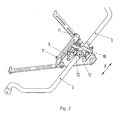
- Fig. 2 shows an example of a coupling device 6 (see Fig. 1 ), wherein the coupling device 6 has a blocking device 10 for the stabilizer 3.
- the blocking device 10 is designed switchable, wherein the blocking device 10, for example, with the aid of an electric motor 9, preferably in the direction x along the axis of the stabilizer 3 can be moved. By moving the blocking device 10 in the direction x, a positive connection can be produced or also be released again. If the blocking device 10 is pushed over the form-locking elements 12 provided on the stabilizer 3, then the stabilizer 3 is blocked by positive locking and thus there is a moment support of the stabilizer 3 on the vehicle body.
- the coupling device 6 is connected to the vehicle body with the aid of fastening elements 11. This connection is preferably in the region of the vehicle front axle, for example on a cross member.
- the electric motor 9 is designed, for example, as an AC motor in conjunction with a linear drive.
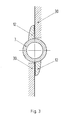
- Fig. 3 shows a section through a stabilizer 3, wherein the stabilizer 3 has one or more, in the example shown two positive locking elements 12 which act with appropriate positioning of the blocking device 30 with the latter together so that the stabilizer 3 is blocked against rotation.
- the blocking device 30 can be moved for positioning, for example, along the axis of the stabilizer 3.
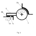
- Fig. 4 shows a schematic sectional view of a stabilizer 3 with a positive locking element 12.
- blocking elements 30a, 30b are provided for blocking the stabilizer 3 designed as stops.
- a fixed blocking element 30a with two stops is provided for blocking the stabilizer 3 .
- a switchable blocking element 30b is provided for blocking the stabilizer 3 .
- the switchable blocking element 30b is designed to be displaceable along a displacement direction VA, whereby a switchable stop for the stabilizer 3 is provided. If the blocking is switched on, a supporting force F S acts on the positive-locking element 12 connected to the stabilizer 3.
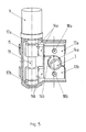
- the Fig. 5 and 6 show a coupling device 6 (see Fig. 1 ) with two rotatably mounted clamping pieces 13a, 13b, by means of which the stabilizer 3 can be blocked by frictional engagement.
- the clamping pieces 13a, 13b are each rotatably supported with the aid of bearing pins 18a, 18b.
- the clamping pieces 13a, 13b facing the stabilizer 3 each have a rubber coating 14a, 14b.
- the clamping pieces 13a, 13b can essentially be made of a metal or of a metal alloy, for example steel or aluminum.
- Fig. 5 are the clamping pieces 13a, 13b shown untwisted, with no frictional engagement with the stabilizer 3, ie there is no torque support of the stabilizer 3 relative to the vehicle body.
- the stabilizer 3 By rotation of the clamping pieces 13a, 13b, the stabilizer 3 can be frictionally blocked.
- the rotation of the clamping pieces 13a, 13b takes place with the aid of worm drives 16a, 16b, each consisting of a worm and a toothed segment, wherein a common shaft 19 is provided for actuating the worm drives 16a, 16b.
- Bearing devices 17a, 17b are provided for the shaft 19.
- the shaft 19 can be driven, for example, by an electric motor 9, for example an AC motor.
- a housing 15 may be provided at least for the shaft 19 and the worm drives 16a, 16b.
- Fig. 7 shows schematically and in section an example of a stabilizer 3 and based on the principle of frictional locking device.
- the blocking device is turned on by an active clamping force AK, with the aid of an electric motor, is applied, whereby the clamping pieces 13a, 13b are pressed against the stabilizer 3.
- a torque on the stabilizer 3 then causes a frictional force F R between the stabilizer 3 and the clamping pieces 13a, 13b, through which the stabilizer 3 is blocked.
- the diameter of the stabilizer 3 in the region in which the frictional engagement takes place is widened.
- the switchable blocking device may also be formed such that a preferably connected to the stabilizer 3 in the middle of the stabilizer 3 lever 23 is provided, which is connected at least by means of an actuator 24 to the vehicle body.
- the actuator 24 is released during normal driving. To lift the vehicle, the actuator 24 is blocked and the actuators 4a, 4b are actuated in the same direction.
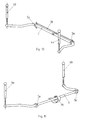
- the Fig. 9 . 10 and 11 show coupling devices 6 with at least one spring device for torque-supporting the stabilizer 3 on the vehicle body.
- the preferably soft spring device is at least largely without disturbing effect, since the center of the stabilizer 3 is not rotated relative to the vehicle body. Even with a roll stabilization, the center of the stabilizer 3 does not rotate relative to the vehicle body. It can thus be an undisturbed roll compensation by means of optionally actuated in opposite directions actuators 4a, 4b.
- the stiffness of the stabilizer 3 is active in series with the spring device of the coupling device 6 as a suspension spring in normal driving, which acts parallel to the actual bodybuilder. The stiffness of the actual bodybuilder must therefore be chosen softer, in order to achieve the sum required for the vehicle body vertical spring rate.
- the spring device may be formed as arranged substantially parallel to the stabilizer 3 torsion bar spring 26, wherein the torsion bar spring is connected via a non-rotatable connection 27 with the stabilizer 3.
- the two wheels 1a, 1b facing ends of the illustrated in the example as a torsion spring 26 spring device are built-up take-driving provided.
- the spring device may also be formed as a sheet metal profile 28, which may be integrally formed at its two ends with the inclusion of the stabilizer bearings 5a, 5b.
- the spring device may be formed as a leaf spring 29, which preferably acts centrally on the stabilizer 3.
- the spring device eg as a leg spring, possible.
- the coupling device 6 according to the invention for variable moment support of the stabilizer may preferably be arranged in the front region of the motor vehicle, i. in the region of a front axle, be arranged. Alternatively or additionally, one or more such coupling devices 6 may also be located in another area, e.g. be arranged in the region of a rear axle.
- a reliable leveling function is provided, e.g. can be used on the front axle for spoiler protection.
- the activation of the leveling function can be done manually with the engine running, e.g. be done by means of a switch, which in the vehicle interior, for. in the center console, can be arranged.
- an automatic deactivation of the level lift function can be provided when a certain maximum speed is exceeded.
- the coupling device 6 for torque-supporting the stabilizer 3 on the vehicle body may comprise a switchable blocking device and / or at least one spring device.
Landscapes
- Engineering & Computer Science (AREA)
- Mechanical Engineering (AREA)
- Chemical & Material Sciences (AREA)
- Combustion & Propulsion (AREA)
- Transportation (AREA)
- Vehicle Body Suspensions (AREA)
- Springs (AREA)
Applications Claiming Priority (1)
| Application Number | Priority Date | Filing Date | Title |
|---|---|---|---|
| DE102007006589A DE102007006589A1 (de) | 2007-02-09 | 2007-02-09 | Kraftfahrzeug mit einem Fahrzeugaufbau und mit einem Fahrwerk |
Publications (3)
| Publication Number | Publication Date |
|---|---|
| EP1955877A2 true EP1955877A2 (fr) | 2008-08-13 |
| EP1955877A3 EP1955877A3 (fr) | 2010-04-21 |
| EP1955877B1 EP1955877B1 (fr) | 2014-05-14 |
Family
ID=39284189
Family Applications (1)
| Application Number | Title | Priority Date | Filing Date |
|---|---|---|---|
| EP07024358.9A Not-in-force EP1955877B1 (fr) | 2007-02-09 | 2007-12-15 | Véhicule automobile doté d'une carrosserie et d'un châssis |
Country Status (6)
| Country | Link |
|---|---|
| US (1) | US8140221B2 (fr) |
| EP (1) | EP1955877B1 (fr) |
| JP (1) | JP5289788B2 (fr) |
| KR (1) | KR101409029B1 (fr) |
| CN (1) | CN101239574B (fr) |
| DE (1) | DE102007006589A1 (fr) |
Families Citing this family (18)
| Publication number | Priority date | Publication date | Assignee | Title |
|---|---|---|---|---|
| DE102008002524A1 (de) * | 2008-06-19 | 2009-12-24 | Zf Friedrichshafen Ag | Stabilisator für ein Nutzfahrzeug |
| DE102009054671B4 (de) | 2009-12-15 | 2022-09-29 | Robert Bosch Gmbh | Vorrichtung zur Wankstabilisierung eines Fahrzeugs |
| FR2956713B1 (fr) * | 2010-02-24 | 2012-03-23 | Hutchinson | Lame de ressort composite a articulations pour liaison au sol de vehicule automobile, son procede de fabrication et cette liaison au sol |
| DE102011116034A1 (de) * | 2011-10-17 | 2013-04-18 | GM Global Technology Operations LLC (n. d. Gesetzen des Staates Delaware) | Radaufhängungsvorrichtung für einKraftfahrzeug |
| DE102011056868A1 (de) * | 2011-12-22 | 2013-06-27 | Dr. Ing. H.C. F. Porsche Aktiengesellschaft | Fahrwerk eines Kraftfahrzeugs |
| DE102013110953A1 (de) * | 2013-10-02 | 2015-04-02 | Dr. Ing. H.C. F. Porsche Aktiengesellschaft | Verfahren zum Betreiben einer Stabilisatoranordnung |
| US9150078B2 (en) * | 2013-10-18 | 2015-10-06 | GM Global Technology Operations LLC | Vehicle suspension apparatus with bar and body load reaction component for ride height management |
| CN104527363B (zh) * | 2014-11-27 | 2017-07-28 | 郑州宇通客车股份有限公司 | 横向稳定装置及使用该横向稳定装置的车辆 |
| DE102014225284A1 (de) * | 2014-12-09 | 2016-06-09 | Zf Friedrichshafen Ag | Koppelstange für ein Fahrwerksystem |
| CN105082924A (zh) * | 2015-08-24 | 2015-11-25 | 华一精密机械(昆山)有限公司 | 一种汽车平衡杆 |
| CN105667243A (zh) * | 2016-04-06 | 2016-06-15 | 华一精密机械(昆山)有限公司 | 一种平衡杆 |
| US20190161089A1 (en) * | 2017-11-28 | 2019-05-30 | GM Global Technology Operations LLC | Control of chassis systems in relation to aerodynamic loads |
| CN109484125B (zh) * | 2018-11-29 | 2021-06-25 | 北京汽车股份有限公司 | 车辆悬架稳定器及车辆 |
| KR102634403B1 (ko) * | 2019-03-18 | 2024-02-06 | 현대자동차주식회사 | 차량용 스태빌라이저 장치 |
| KR102138687B1 (ko) * | 2019-05-27 | 2020-07-28 | 주식회사 센트랄 | 스트러트 현가장치 |
| DE102020213644B4 (de) | 2020-10-29 | 2022-05-12 | Ford Global Technologies, Llc | Federanordnung |
| DE102021125995A1 (de) | 2021-10-07 | 2023-04-13 | Dr. Ing. H.C. F. Porsche Aktiengesellschaft | System zur Kompensation von Aufbaubewegungen in einem Kraftfahrzeug |
| CN114906267B (zh) * | 2022-06-16 | 2023-11-28 | 湖南山地电动车有限公司 | 一种适用于山地爬坡的电动车 |
Citations (3)
| Publication number | Priority date | Publication date | Assignee | Title |
|---|---|---|---|---|
| US20040090019A1 (en) | 2001-04-10 | 2004-05-13 | Philippe Germain | Vehicle roll control system |
| EP1609634A1 (fr) | 2004-06-24 | 2005-12-28 | GM Global Technology Operations, Inc. | Chassis pour véhicule à moteur et système de régulation de niveau |
| JP2006088752A (ja) | 2004-09-21 | 2006-04-06 | Toyota Motor Corp | 車両懸架システム |
Family Cites Families (29)
| Publication number | Priority date | Publication date | Assignee | Title |
|---|---|---|---|---|
| GB1244872A (en) * | 1968-08-20 | 1971-09-02 | Rover Co Ltd | Vehicle suspensions |
| DE1811613A1 (de) * | 1968-11-29 | 1970-07-09 | Demag Ag | Aussenbackenbremse |
| JPS6072713U (ja) * | 1983-10-27 | 1985-05-22 | 中央発條株式会社 | 車輌懸架装置用スタビライザ装置 |
| JPS6072714U (ja) * | 1983-10-27 | 1985-05-22 | 中央発條株式会社 | 車輌懸架装置用スタビライザ装置 |
| JPS6147709U (ja) * | 1984-09-03 | 1986-03-31 | トヨタ自動車株式会社 | マクフア−ソンストラツト式サスペンシヨン |
| JPS6280112A (ja) * | 1985-10-02 | 1987-04-13 | Toyota Motor Corp | サスペンシヨン制御装置 |
| JPS6432918A (en) * | 1987-07-28 | 1989-02-02 | Mitsubishi Motors Corp | Active suspension controller |
| US5004257A (en) * | 1988-09-21 | 1991-04-02 | Macisaac William L | Vehicle suspension system |
| DE4125285C2 (de) * | 1991-07-31 | 1996-12-12 | Daimler Benz Ag | Zylinder-Kolbenaggregat |
| US5368337A (en) * | 1993-12-28 | 1994-11-29 | Torres; Santos | Adjustable stabilizer clamp |
| JP2940656B2 (ja) * | 1994-03-30 | 1999-08-25 | 日産ディーゼル工業株式会社 | 車両用サスペンション装置 |
| TW355699B (en) * | 1995-08-21 | 1999-04-11 | Kiectic Ltd | Vehicular suspension systems |
| DE19702241A1 (de) * | 1997-01-24 | 1998-02-12 | Mannesmann Sachs Ag | Fahrwerk für ein Kraftfahrzeug |
| US5911796A (en) * | 1997-02-25 | 1999-06-15 | Buck; David A. | Jaw assembly |
| US6374953B1 (en) * | 1999-11-30 | 2002-04-23 | Alan V. Casas | Vertical plunger brake control device |
| DE10018776C1 (de) * | 2000-04-15 | 2001-07-26 | Porsche Ag | Lagerung für einen Stabilisator einer Radaufhängung für Kraftfahrzeuge |
| CZ14789U1 (cs) * | 2001-06-22 | 2004-10-11 | Rudolf Ing. Müller | Mobilní čerpací stanice |
| DE10227416A1 (de) * | 2002-06-20 | 2004-01-08 | Zf Friedrichshafen Ag | Federungssystem für ein Fahrzeug |
| US6883813B2 (en) * | 2003-02-26 | 2005-04-26 | The Boler Company | Independent paddle lift axle suspension system |
| JP4075751B2 (ja) * | 2003-09-17 | 2008-04-16 | トヨタ自動車株式会社 | アクティブスタビライザ装置 |
| JP2005125834A (ja) * | 2003-10-21 | 2005-05-19 | Toyota Motor Corp | スタビライザ装置 |
| JP4123148B2 (ja) * | 2003-12-10 | 2008-07-23 | 日産自動車株式会社 | 車両用スタビライザ |
| DE102004030466A1 (de) * | 2004-06-24 | 2006-03-02 | Adam Opel Ag | Fahrwerk für Kraftfahrzeuge und Niveauregulierungssystem |
| KR100629799B1 (ko) * | 2004-12-01 | 2006-09-28 | 현대모비스 주식회사 | 모터를 이용한 액티브롤콘트롤 시스템 |
| FR2880586B1 (fr) * | 2005-01-10 | 2013-02-15 | Renault Sas | Dispositif de suspension pour barres de torsion |
| DE102005001827B4 (de) * | 2005-01-14 | 2016-08-25 | Audi Ag | Stabilisator für Kraftfahrzeug |
| JP2006207644A (ja) * | 2005-01-26 | 2006-08-10 | Toyota Motor Corp | 車両用サスペンション装置 |
| JP2007015592A (ja) * | 2005-07-08 | 2007-01-25 | Honda Motor Co Ltd | 車両用サスペンション装置 |
| JP2009227004A (ja) * | 2008-03-19 | 2009-10-08 | Toyota Motor Corp | サスペンション装置 |
-
2007
- 2007-02-09 DE DE102007006589A patent/DE102007006589A1/de not_active Ceased
- 2007-12-15 EP EP07024358.9A patent/EP1955877B1/fr not_active Not-in-force
-
2008
- 2008-02-05 KR KR1020080011454A patent/KR101409029B1/ko not_active Expired - Fee Related
- 2008-02-05 CN CN2008100054947A patent/CN101239574B/zh not_active Expired - Fee Related
- 2008-02-08 JP JP2008028990A patent/JP5289788B2/ja not_active Expired - Fee Related
- 2008-02-11 US US12/029,135 patent/US8140221B2/en not_active Expired - Fee Related
Patent Citations (3)
| Publication number | Priority date | Publication date | Assignee | Title |
|---|---|---|---|---|
| US20040090019A1 (en) | 2001-04-10 | 2004-05-13 | Philippe Germain | Vehicle roll control system |
| EP1609634A1 (fr) | 2004-06-24 | 2005-12-28 | GM Global Technology Operations, Inc. | Chassis pour véhicule à moteur et système de régulation de niveau |
| JP2006088752A (ja) | 2004-09-21 | 2006-04-06 | Toyota Motor Corp | 車両懸架システム |
Also Published As
| Publication number | Publication date |
|---|---|
| US20080195278A1 (en) | 2008-08-14 |
| CN101239574A (zh) | 2008-08-13 |
| JP2008195386A (ja) | 2008-08-28 |
| CN101239574B (zh) | 2012-05-02 |
| EP1955877A3 (fr) | 2010-04-21 |
| KR101409029B1 (ko) | 2014-06-18 |
| US8140221B2 (en) | 2012-03-20 |
| EP1955877B1 (fr) | 2014-05-14 |
| JP5289788B2 (ja) | 2013-09-11 |
| DE102007006589A1 (de) | 2008-08-14 |
| KR20080074762A (ko) | 2008-08-13 |
Similar Documents
| Publication | Publication Date | Title |
|---|---|---|
| EP1955877B1 (fr) | Véhicule automobile doté d'une carrosserie et d'un châssis | |
| EP2254762B1 (fr) | Suspension de roue pour les roues directrices de véhicules à moteur | |
| EP1970226B1 (fr) | Suspension de roue pour véhicules automobiles | |
| EP2493708B1 (fr) | Suspension de véhicule | |
| EP2389299B1 (fr) | Dispositif de stabilisateur sur une suspension de roue de vehicule motorise | |
| WO2003022604A2 (fr) | Regulation de niveau electromecanique d'une automobile | |
| DE102008023891A1 (de) | Vorrichtung zur Höhenverstellung der Karosserie eines Kraftfahrzeuges | |
| DE102007007214A1 (de) | Anordnung eines Stabilisators an einer Radaufhängung für Kraftfahrzeuge | |
| DE102009047100B4 (de) | Radaufhängung für ein Fahrzeug | |
| DE102013211660B4 (de) | Verfahren und Vorrichtung zur Höhenverstellung des Aufbaus eines Kraftfahrzeugs | |
| EP1935680A1 (fr) | Suspension de roue pour un véhicule automobile | |
| EP3079928A2 (fr) | Suspension activement réglable pour les roues d'un essieu de véhicule à moteur | |
| EP1935677A1 (fr) | Suspension de roue pour un véhicule automobile | |
| DE102008060477B4 (de) | Anordnung zur Niveauregulierung eines Fahrzeugs | |
| EP3027439A1 (fr) | Système de barres de torsion pour une suspension de roue d'un véhicule automobile | |
| EP1147968B2 (fr) | Transpalette à cinq roues | |
| DE102010061154B4 (de) | Aktive Verbundlenkerachse | |
| DE102009053123A1 (de) | Einrichtung zur aktiven Höhenverstellung einer Karosserie eines Fahrzeuges | |
| DE102020113865A1 (de) | Radaufhängung | |
| DE102007052038A1 (de) | Hydraulischer Stabilisator, insbesondere für Fahrwerke und Fahrerhausauflagerungen | |
| DE102014217247A1 (de) | Stabilisierungsanordnung für ein Neigefahrwerk eines Fahrzeugs sowie Neigefahrwerk | |
| DE102006057891A1 (de) | Wankstabilisierungs- und Wankdämpfungs-Anordnung für ein zweispuriges Fahrzeug | |
| DE102005042821A1 (de) | Aktor für eine Radaufhängung | |
| AT523497B1 (de) | Radaufhängung | |
| DE102005060504B3 (de) | Niveauregulierung |
Legal Events
| Date | Code | Title | Description |
|---|---|---|---|
| PUAI | Public reference made under article 153(3) epc to a published international application that has entered the european phase |
Free format text: ORIGINAL CODE: 0009012 |
|
| AK | Designated contracting states |
Kind code of ref document: A2 Designated state(s): AT BE BG CH CY CZ DE DK EE ES FI FR GB GR HU IE IS IT LI LT LU LV MC MT NL PL PT RO SE SI SK TR |
|
| AX | Request for extension of the european patent |
Extension state: AL BA HR MK RS |
|
| PUAL | Search report despatched |
Free format text: ORIGINAL CODE: 0009013 |
|
| RAP1 | Party data changed (applicant data changed or rights of an application transferred) |
Owner name: DR. ING. H.C. F. PORSCHE AG |
|
| AK | Designated contracting states |
Kind code of ref document: A3 Designated state(s): AT BE BG CH CY CZ DE DK EE ES FI FR GB GR HU IE IS IT LI LT LU LV MC MT NL PL PT RO SE SI SK TR |
|
| AX | Request for extension of the european patent |
Extension state: AL BA HR MK RS |
|
| 17P | Request for examination filed |
Effective date: 20101021 |
|
| 17Q | First examination report despatched |
Effective date: 20101123 |
|
| AKX | Designation fees paid |
Designated state(s): DE FR GB IT |
|
| GRAP | Despatch of communication of intention to grant a patent |
Free format text: ORIGINAL CODE: EPIDOSNIGR1 |
|
| INTG | Intention to grant announced |
Effective date: 20140206 |
|
| RIN1 | Information on inventor provided before grant (corrected) |
Inventor name: HUNN, THOMAS Inventor name: DIETZ, MATTHIAS Inventor name: SCHULZ, ACHIM Inventor name: KOCH, THORSTEN Inventor name: BECKER, MICHAEL |
|
| GRAS | Grant fee paid |
Free format text: ORIGINAL CODE: EPIDOSNIGR3 |
|
| GRAA | (expected) grant |
Free format text: ORIGINAL CODE: 0009210 |
|
| AK | Designated contracting states |
Kind code of ref document: B1 Designated state(s): DE FR GB IT |
|
| REG | Reference to a national code |
Ref country code: GB Ref legal event code: FG4D Free format text: NOT ENGLISH |
|
| REG | Reference to a national code |
Ref country code: DE Ref legal event code: R096 Ref document number: 502007013105 Country of ref document: DE Effective date: 20140626 |
|
| REG | Reference to a national code |
Ref country code: DE Ref legal event code: R097 Ref document number: 502007013105 Country of ref document: DE |
|
| PLBE | No opposition filed within time limit |
Free format text: ORIGINAL CODE: 0009261 |
|
| STAA | Information on the status of an ep patent application or granted ep patent |
Free format text: STATUS: NO OPPOSITION FILED WITHIN TIME LIMIT |
|
| 26N | No opposition filed |
Effective date: 20150217 |
|
| PG25 | Lapsed in a contracting state [announced via postgrant information from national office to epo] |
Ref country code: IT Free format text: LAPSE BECAUSE OF FAILURE TO SUBMIT A TRANSLATION OF THE DESCRIPTION OR TO PAY THE FEE WITHIN THE PRESCRIBED TIME-LIMIT Effective date: 20140514 |
|
| REG | Reference to a national code |
Ref country code: DE Ref legal event code: R097 Ref document number: 502007013105 Country of ref document: DE Effective date: 20150217 |
|
| GBPC | Gb: european patent ceased through non-payment of renewal fee |
Effective date: 20141215 |
|
| REG | Reference to a national code |
Ref country code: FR Ref legal event code: ST Effective date: 20150831 |
|
| PG25 | Lapsed in a contracting state [announced via postgrant information from national office to epo] |
Ref country code: GB Free format text: LAPSE BECAUSE OF NON-PAYMENT OF DUE FEES Effective date: 20141215 |
|
| PG25 | Lapsed in a contracting state [announced via postgrant information from national office to epo] |
Ref country code: FR Free format text: LAPSE BECAUSE OF NON-PAYMENT OF DUE FEES Effective date: 20141231 |
|
| PGFP | Annual fee paid to national office [announced via postgrant information from national office to epo] |
Ref country code: DE Payment date: 20200115 Year of fee payment: 13 |
|
| REG | Reference to a national code |
Ref country code: DE Ref legal event code: R119 Ref document number: 502007013105 Country of ref document: DE |
|
| PG25 | Lapsed in a contracting state [announced via postgrant information from national office to epo] |
Ref country code: DE Free format text: LAPSE BECAUSE OF NON-PAYMENT OF DUE FEES Effective date: 20210701 |