EP1956184B1 - Verfahren und Vorrichtung zur Pipelineverbindung - Google Patents
Verfahren und Vorrichtung zur Pipelineverbindung Download PDFInfo
- Publication number
- EP1956184B1 EP1956184B1 EP20080250480 EP08250480A EP1956184B1 EP 1956184 B1 EP1956184 B1 EP 1956184B1 EP 20080250480 EP20080250480 EP 20080250480 EP 08250480 A EP08250480 A EP 08250480A EP 1956184 B1 EP1956184 B1 EP 1956184B1
- Authority
- EP
- European Patent Office
- Prior art keywords
- pipeline
- guide means
- frame
- guide
- pipe
- Prior art date
- Legal status (The legal status is an assumption and is not a legal conclusion. Google has not performed a legal analysis and makes no representation as to the accuracy of the status listed.)
- Not-in-force
Links
- 238000000034 method Methods 0.000 title claims abstract description 41
- 238000005520 cutting process Methods 0.000 claims abstract description 32
- 230000008878 coupling Effects 0.000 claims abstract description 13
- 238000010168 coupling process Methods 0.000 claims abstract description 13
- 238000005859 coupling reaction Methods 0.000 claims abstract description 13
- 238000001514 detection method Methods 0.000 claims description 2
- 230000013011 mating Effects 0.000 claims description 2
- 241001317177 Glossostigma diandrum Species 0.000 description 17
- 239000012530 fluid Substances 0.000 description 2
- 238000009412 basement excavation Methods 0.000 description 1
- 238000004891 communication Methods 0.000 description 1
- 229930195733 hydrocarbon Natural products 0.000 description 1
- 150000002430 hydrocarbons Chemical class 0.000 description 1
- 238000004519 manufacturing process Methods 0.000 description 1
- 238000012986 modification Methods 0.000 description 1
- 230000004048 modification Effects 0.000 description 1
- 230000008569 process Effects 0.000 description 1
- 230000008439 repair process Effects 0.000 description 1
- 238000012876 topography Methods 0.000 description 1
- XLYOFNOQVPJJNP-UHFFFAOYSA-N water Substances O XLYOFNOQVPJJNP-UHFFFAOYSA-N 0.000 description 1
Images




Classifications
-
- F—MECHANICAL ENGINEERING; LIGHTING; HEATING; WEAPONS; BLASTING
- F16—ENGINEERING ELEMENTS AND UNITS; GENERAL MEASURES FOR PRODUCING AND MAINTAINING EFFECTIVE FUNCTIONING OF MACHINES OR INSTALLATIONS; THERMAL INSULATION IN GENERAL
- F16L—PIPES; JOINTS OR FITTINGS FOR PIPES; SUPPORTS FOR PIPES, CABLES OR PROTECTIVE TUBING; MEANS FOR THERMAL INSULATION IN GENERAL
- F16L1/00—Laying or reclaiming pipes; Repairing or joining pipes on or under water
- F16L1/26—Repairing or joining pipes on or under water
-
- E—FIXED CONSTRUCTIONS
- E21—EARTH OR ROCK DRILLING; MINING
- E21B—EARTH OR ROCK DRILLING; OBTAINING OIL, GAS, WATER, SOLUBLE OR MELTABLE MATERIALS OR A SLURRY OF MINERALS FROM WELLS
- E21B43/00—Methods or apparatus for obtaining oil, gas, water, soluble or meltable materials or a slurry of minerals from wells
- E21B43/01—Methods or apparatus for obtaining oil, gas, water, soluble or meltable materials or a slurry of minerals from wells specially adapted for obtaining from underwater installations
- E21B43/0107—Connecting of flow lines to offshore structures
-
- Y—GENERAL TAGGING OF NEW TECHNOLOGICAL DEVELOPMENTS; GENERAL TAGGING OF CROSS-SECTIONAL TECHNOLOGIES SPANNING OVER SEVERAL SECTIONS OF THE IPC; TECHNICAL SUBJECTS COVERED BY FORMER USPC CROSS-REFERENCE ART COLLECTIONS [XRACs] AND DIGESTS
- Y10—TECHNICAL SUBJECTS COVERED BY FORMER USPC
- Y10T—TECHNICAL SUBJECTS COVERED BY FORMER US CLASSIFICATION
- Y10T137/00—Fluid handling
- Y10T137/598—With repair, tapping, assembly, or disassembly means
- Y10T137/612—Tapping a pipe, keg, or apertured tank under pressure
Definitions
- the present invention relates to a method and apparatus for connecting a connector pipe to a pipeline.
- the invention provides a method and apparatus for removing part of a pipeline and replacing that part of the pipeline with a spool piece.
- the method and apparatus is also suitable for connecting an end of an existing pipeline to a new pipeline, such as a riser.
- a pipeline repair method is also disclosed in US 5,458,439 .
- a method of connecting a connector pipe to a pipeline having a throughbore comprising the steps of:
- steps (a), (b) and (f) enable the location of the connector pipe to be readily established relative to the bore and the end of the pipeline.
- steps (a), (b) and (f) enable the location of the connector pipe to be readily established relative to the bore and the end of the pipeline.
- the dimensions of the frame and the support relative to the pipeline, and each other can be calculated prior to the connection operation to facilitate alignment and connection of the connector pipe with the pipeline.
- the method can include the step of removing part of a cover surrounding the pipeline.
- Step (b) can include locating the guide means on a portion of the uncovered pipeline.
- the method can include excavating the seabed in the region of the pipeline to be cut.
- the method of step (b) includes providing a guide member attached to a clamp and clamping the guide member to the pipeline. Since the clamp is centred on the pipeline, the relative location of the guide member and the axis of the pipeline is known.
- the method can include repeating steps (a) to (h) and step (b) can include locating the guide means at an axially spaced position on the pipeline.
- the method can include detecting the relative position of each guide means during step (b) to measure the distance between the two guide means and thereby allow calculation of the distance between the cut ends of the pipeline. This information can be used to enable a spool piece of the requisite length to be manufactured for subsequent coupling to the connector pipes once these have been connected at the ends of the pipeline.
- the method of step (c) can include providing a cutting tool with a positioning member and mating the positioning member of the cutting tool with the part of the guide means, such as the guide member, to correctly locate the cutting tool.
- the method can include the step of retrieving the cutting tool following step (d).
- the method can also include retrieving part of the guide means following step (d).
- This method step can include retrieving the guide member and coupling a second guide member to the clamp.
- Method step (f) can include indirectly coupling the support to a portion of the guide means.
- the method can further include gripping the pipeline and adjusting the height of the pipeline. This can be achieved by clamping the frame around the pipeline, supporting the frame and providing the frame with an actuation means for adjusting the height.
- the method step (g) can include the step of actuating at least part of the support or the frame to correctly orient the connector pipe relative to the pipeline.
- the method can include the step of pivoting the positioning means of the frame to manoeuvre the connector pipe relative to the pipeline.
- the method can include remotely connecting the pipe to the pipeline, using a remotely operable vehicle to actuate and control steps (b) to (h).
- Step (h) can include actuating movement of at least part of the support to move the connector pipe towards the pipeline.
- an apparatus for connecting a connector pipe to a pipeline having a throughbore comprising:
- the guide means can comprise a guide member.
- the cutting tool can have a positioning member arranged for releasable coupling with the guide member such that the cutting tool is operable to cut the pipeline at a known position relative to the guide means.
- the guide means can be provided with a detection means, such as a transponder for detecting the relative location of another transponder.
- a detection means such as a transponder for detecting the relative location of another transponder.
- the other transponder can be provided on a further guide means located at an axially spaced location on the pipeline.
- the support and the guide means can be indirectly connectable using the positioning means and the frame.
- the guide means can also comprise a second guide member. Both of the guide members can be releasably connectable to the clamp. The two guide members can be interchangeably connectable to the clamp.
- the second guide member can be provided with a positioning member cooperable with a frame.
- the frame and the support are each provided with a cooperative positioning means so that the support is engageable with the frame.
- the frame positioning means is pivotable for substantially aligning the pipe and the pipeline.
- the frame can be provided with a clamp for gripping the pipeline and an actuation means for adjusting the height of the clamp.
- the actuator can comprise a remotely operable vehicle for remotely actuating and controlling the connection of the pipe and the pipeline.
- the frame can be a pipe handling frame.
- the support can be a mudmat.
- One end of the pipe can have a connector for connecting the pipe to the pipeline and one end of the pipe can be provided with a connector for coupling the pipe to an end of a spool piece.
- Figure 1 shows part of a subsea pipeline 10 laid along a seabed 14.
- the pipeline 10 has a throughbore and a longitudinal axis 11.
- An outer concrete cover 12 surrounds the pipeline 10 to ensure that the pipeline 10 is negatively buoyant so that the pipeline 10 remains on the seabed 14 when the pipeline 10 is devoid of contents.
- the pipeline 10 has a length, which, due to any number of reasons, is required to be replaced. The method steps of the pipeline 10 replacement operation will be described hereinafter, following the description of components shown in figures 1 , 3 , 4 , 6 and 10 .
- Figure 3 shows a clamp 20, a guide attachment 23 and a short guide post 22.
- the clamp 20 has two semi-annular jaws that are pivotably attached to one another at one end and separable at the other end to enable the clamp 20 to be assembled and disassembled over the pipeline 10.
- the clamp 20 provides a fixed reference point around the central axis 11 of the pipeline 10 for metrology, the cutting operation and (indirectly) the connecting operation.
- the guide attachment 23 couples the removable short guide post 22 to the clamp 20.
- the clamp 20 is provided with an acoustic metrology transponder in a mounting 24.
- the transponder is arranged to communicate with a similar transponder (not shown) provided on a similar clamp (not shown) at an axially spaced location along the pipeline 10, as will be described hereinafter.
- FIG. 4 shows the clamp 20 with the guide attachment 23 coupled to a longer guide post 26.
- a pipe handling frame shown generally at 30 in Figure 4 has a female positioning member 38 that is cooperable with the long guide post 26 in order that the pipe handling frame 30 is correctly positioned relative to the clamp 20.
- the pipe handling frame 30 has planar feet 33 that are adapted to contact the seabed 14 in use and support the pipe handling frame 30 in a substantially upright position. Legs 35 extend perpendicular from the feet 33.
- the pipe handling frame 30 further comprises a frame clamp 31 located between the legs 35.
- the frame clamp 31 has two semi-annular jaws adapted to clamp around the pipeline 10 and concrete cover 12 in a similar manner to the clamp 20.
- the frame 30 also has pistons 39 attached to the frame clamp 31.
- the pistons 39 are actuable to control the height of the clamp 31 relative to the feet 33.
- An upper portion of the pipe handling frame 30 is also provided with a winch 32.
- a strut 37 extends parallel with the pipeline axis 11 from the frame clamp 31.
- the strut 37 carries a guide post 34 pivotally attached at a pivot point 36.
- Figure 6 shows a support in the form of a mudmat 50 having feet 53.
- the mudmat 50 has a support guide post 54 extending perpendicular to the feet 53 and a female positioning arm 58 angled away from the feet 53.
- the positioning arm 58 of the mudmat 50 is cooperable with guide post 34 of the handling frame 30.
- a support 75 is fixed to the mudmat 50 perpendicular to the feet 53.
- the support 75 carries a connecting pipe 70 having a throughbore with an axis 71, one end of which is offset from the other.
- One end of the connector pipe 70 is provided with an end connector 72 and another end of the connector pipe 70 has a hub 74.
- the end connector 72 is a MorgripTM connector that permits axial movement of the connector 72 over the pipeline 10 in one direction and once connected is adapted to substantially restrict removal of the end connector 72 from the pipeline 10 and to provide a fluid tight, pressure retaining seal.
- FIG. 10 A similar connecting pipe 170 and mudmat 150 are shown in Fig. 10 , attached to another axially spaced cut end of the pipeline. 10. Like components are marked with a similar reference numeral having a prefix "1".
- Figure 10 also shows a spool piece 96 that serves as the conduit for replacing part of the pipeline 10 that has been removed.
- the spool piece 96 is coupled to a spool lifting frame 90 by means of ties 92.
- the spool lifting frame 90 is manoeuvred by supports 94 coupled to a surface vessel (not shown).
- the spool piece 96 has a hub 98, 198 at each end for respective connection with the hubs 74, 174 of the connector pipes 70, 170.
- Equipment such as the pipe handling frame 30 and the frame guide post 34, as well as the connection between the frame guide post 34 and the positioning arm 58 of the mudmat 50 is calibrated such that the end connector 72 can be accurately aligned with a cut end 10c of the pipeline 10. This can be achieved since the distance between the guide post 22 and the plane of the cut section 28 is predetermined.
- part of the pipeline 10 is required to be replaced with the spool piece 96. It is intended that the replacement operation is achieved without the use of subsea divers.
- the seabed 14 is excavated beneath part of the pipeline 10.
- a portion of the concrete cover 12 is separated from the pipeline 10 using high pressure water jets or similar tools known in the art.
- the longitudinal weld seam (not shown) is removed from a length of the pipeline 10 in the region that is to be cut, in order to ensure that the outer surface of the pipeline is substantially circular in section. This prepares the pipeline 10 for the cutting and connecting operation.
- This excavation of the seabed 14 and removal of part of the cover 12 are procedures that are repeated at an axially spaced location (not shown) along the pipeline 10.
- the jaws of the clamp 20 are positioned around the portion of pipeline 10 where the concrete cover 12 and weld seam has been removed such that the short removable guide post 22 is extending substantially perpendicular to the pipeline axis 11.
- the clamp 20 is secured in this position around the pipeline 10 by a remotely operated vehicle (ROV). This procedure is also repeated at the axially spaced location along the pipeline 10 where the cover 12 has been removed.
- ROV remotely operated vehicle
- the acoustic metrology transponder in the mounting 24 communicates with a similar transponder associated with the guide means at the axially spaced location to accurately determine the distance therebetween.
- the required length of the spool piece 96 can be calculated using the measured distance between the transponders and the known reach of the cutting tool from the transponder mounting 24.
- a cutting tool (not shown) is suitably modified to include a female connecting member that is arranged to mate with the short guide post 22 of the clamp 20.
- the cutting tool is landed on the pipeline 10 and secured at a set position on the short guide post 22 and also to the pipeline 10, together with other factors such as the required end-to-end configuration of the spool piece 96.
- the cutting tool is removed from the short guide post 22, which is also disconnected and then retrieved from the guide attachment 23.
- the long guide post 26 is then attached to the clamp 20 via the guide attachment 23.
- the long guide post 26 is provided to correctly orient the pipe handling frame 30 with reference to the clamp 20.
- the guide member 38 of the pipe handling frame 30 is landed on the guide post 26.
- the pipe handling frame 30 is supported on the seabed 14 by the feet 33.
- the jaws of the frame clamp 31 are closed around the concrete cover 12 of the pipeline 10 to secure the pipe handling frame 30 in position and grip the pipeline 10.
- the hydraulic pistons 39 of the pipe handling frame 30 are actuated by the ROV to raise the pipeline 10 above the seabed 14, as shown in figure 4 .
- the force exerted by the pistons 39 in raising the pipeline 10 is reacted out through the feet 33 on the seabed 14.
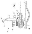
- the long guide post 26 is then be removed from the guide attachment 23 as shown in figure 5 .
- the positioning arm 58 of the mudmat 50 is landed on the frame guide post 34 and locates the mudmat 50 at the correct pre-determined position as shown in figure 6 .
- the ROV engages the winch 32 of the pipe handling frame 30 with a part of the mudmat 50.
- the ROV then actuates the winch 32 to lower the mudmat 50 in a controlled manner as the frame guide post 34 pivots about the pivot point 36, until the frame guide post 34 is oriented substantially parallel to the pipeline 10. This aligns the axis 11 of the pipeline 10 and the axis 71 of the end connector 72.
- the distances between the various guide posts 26, 34 are previously calculated such that there is a clearance (denoted by arrows 78 in figure 7 ) between the cut end 10c of the pipeline 10 and the end connector 72 of the pipe 70.
- the ROV then engages a piston 55 in fluid communication with the positioning arm 58 of the mudmat 50 and the frame guide post 34.
- the ROV actuates the piston 55 to move the positioning arm 58 in an axial direction towards the pipeline 10 such that the end connector 72 locates over the cut end 10c of the pipeline 10.
- the pipe 70 is moved a distance shown by an arrow 79 in Figure 8 .
- the pipe handling frame 30 is recovered to surface following connection of the connector pipe 70 with the pipeline 10.
- the clamp 20 is also removed from the pipeline 10 and recovered to surface as illustrated in Figure 9 .
- the connecting pipe 170 is connected to the other cut end of the pipeline 10 as shown in figure 10 .
- the spool piece 96 (attached to the spool lifting frame 90) is suspended from the surface vessel, and the spool lifting frame 90 is manoeuvred to locate the spool piece 96 in the region of the connector pipes 70, 170.
- the spool piece 96 is guided by the ROV, such that an end region 98 of the spool piece 96 engages the guide post 54 of the mudmat 50 and an end region 198 of the spool piece 96 engages the guide post 154 of the mudmat 150 to correctly position the spool piece 96 relative to the hubs 74, 174.
- the connections between the hubs 74, 174 and the ends 98, 198 of the spool piece 96 are then made up by the ROV to provide a continuous throughbore between the separated parts of the pipeline 10.
- a Morgrip TM end connector 72 was used to seal the connecting pipe 70 to the pipeline 10 in the embodiment.
- any other suitable end connector 72 can be used to effect the connection between the connector pipe 70 and the pipeline 10.
- Other suitable end connectors include Vetco JSS/PSS PLET and Flexconnect TM .
- the winch 32 is engaged to the mudmat 50 to control movement of the mudmat 50.
- the pivot point 36 can be coupled to a rotary actuator (not shown) that is operated by the ROV to pivot the frame guide post 34.
- the rotary actuator and the winch 32 can be used in combination with one another to facilitate the reorientation of the mudmat 50 and align the bores of the pipeline 10 and the pipe 70.
- the pipeline 10 can be coupled to a riser or another pipeline having an axis that is offset relative to the axis 11 of the existing pipeline.
- Previous systems use the seabed 14 as a reference point for connecting the connecting pipe 70 to the pipeline 10.
- the seabed can however be non-uniform with varying topography, and this complicates the design of the equipment needed to reliably achieve the alignment process.
- the present system has a single reference point which is the axis 11 of the existing pipeline 10 to which the cutting operation, the alignment and the connection operation is calibrated. This results in a more accurate and reliable method of connecting the end connector 72 to the existing pipeline 10.
- the cutting tool and the pipe handling frame 30 can be landed on the same guide post to omit the step of replacing the short guide post 22 for the long guide post 26.
Landscapes
- Engineering & Computer Science (AREA)
- Geology (AREA)
- Life Sciences & Earth Sciences (AREA)
- General Engineering & Computer Science (AREA)
- Mining & Mineral Resources (AREA)
- Geochemistry & Mineralogy (AREA)
- Fluid Mechanics (AREA)
- General Life Sciences & Earth Sciences (AREA)
- Physics & Mathematics (AREA)
- Environmental & Geological Engineering (AREA)
- Mechanical Engineering (AREA)
- Earth Drilling (AREA)
- Branch Pipes, Bends, And The Like (AREA)
- Quick-Acting Or Multi-Walled Pipe Joints (AREA)
- Automatic Assembly (AREA)
- Diaphragms For Electromechanical Transducers (AREA)
Claims (14)
- Ein Verfahren zum Verbinden eines Verbinderrohrs (70) mit einer Rohrleitung (10) mit einer Durchgangsbohrung, wobei das Verfahren die folgenden Schritte beinhaltet:(a) Vormontieren des Verbinderrohrs (70) in einer Stütze (75);(b) Bereitstellen eines Führungsmittels, das an einer Klemme (20) angebracht ist, und Klemmen des Führungsmittels an die Rohrleitung (10) an einer bekannten Position relativ zu der Durchgangsbohrung der Rohrleitung (10);(c) Koppeln eines Schneidewerkzeugs an einen Abschnitt des Führungsmittels;(d) Schneiden der Rohrleitung (10) in einer zuvor festgelegten Entfernung von dem Führungsmittel, so dass ein Ende der Rohrleitung (10) geschaffen wird;(e) In-Eingriff-Bringen eines Rahmens (30) mit einem Abschnitt des Führungsmittels und dadurch Anordnen des Rahmens (30) auf der Rohrleitung (10) in einer bekannten Position relativ zu der Durchgangsbohrung und auf einer Seite des Führungsmittels, die von dem Ende der Rohrleitung (10) weg liegt;(f) Koppeln der Stütze (75) über einen Positionierungsarm (58) an einen Führungspfosten (34) des Rahmens (30) an einer bekannten Position;(g) wesentliches Abgleichen des Verbinderrohrs (70) mit dem Ende der Rohrleitung (10), indem der Führungspfosten (34) um einen Schwenkpunkt (36) geschwenkt wird; und(h) Verbinden des Verbinderrohrs (70) mit dem Ende der Rohrleitung (10).
- Verfahren gemäß Anspruch 1, das ferner vor Schritt (b) den Schritt des Entfernens eines Teils einer Hülle (12), die die Rohrleitung (10) umgibt, beinhaltet.
- Verfahren gemäß Anspruch 2, wobei Schritt (b) das Anordnen des Führungsmittels auf einem Abschnitt der freigelegten Rohrleitung (10) umfasst.
- Verfahren gemäß einem der Ansprüche 1 bis 3, das ferner vor Schritt (b) das Ausheben des Meeresbodens (14) in der Region der zu schneidenden Rohrleitung (10) beinhaltet.
- Verfahren gemäß einem der Ansprüche 1 bis 4, das ferner das Wiederholen der Schritte (a) bis (h) für ein zweites Mal an einer entlang der Rohrleitung (10) axial mit Abstand angeordneten Stelle mit einem zweiten Führungsmittel beinhaltet.
- Verfahren gemäß Anspruch 5, das das Erfassen der relativen Position jedes Führungsmittels während Schritt (b) umfasst, um die Entfernung zwischen den zwei Führungsmitteln zu messen und dadurch eine Berechnung der Entfernung zwischen den geschnittenen Enden der Rohrleitung (10) zu ermöglichen.
- Verfahren gemäß einem der Ansprüche 1 bis 6, wobei das Verfahren von Schritt (c) das Versehen eines Schneidewerkzeugs mit einem Positionierungselement und das Passen des Positionierungselements des Schneidewerkzeugs an den Abschnitt des Führungsmittels zum korrekten Anordnen des Schneidewerkzeugs umfasst.
- Verfahren gemäß Anspruch 7, das ferner den Schritt des Einholens des Schneidewerkzeugs nach Schritt (d) beinhaltet.
- Verfahren gemäß einem der Ansprüche 1 bis 8, das ferner das Greifen der Rohrleitung (10) und das Anpassen der Höhe der Rohrleitung (10) im Anschluss an Schritt (f) beinhaltet.
- Eine Vorrichtung zum Verbinden eines Verbinderrohrs (70) mit einer Rohrleitung (10) mit einer Durchgangsbohrung, wobei die Vorrichtung Folgendes beinhaltet:eine Stütze (75) zum Aufnehmen des Verbinderrohrs (70);ein Führungsmittel, das eine Klemme (20) zum Klemmen des Führungsmittels an die Rohrleitung (10) an einer bekannten Stelle relativ zu der Durchgangsbohrung beinhaltet;ein Schneidewerkzeug, das eingerichtet ist, um lösbar an das Führungsmittel gekoppelt zu werden;einen Rahmen (30) zum Koppeln an einen Abschnitt des Führungsmittels, umdadurch den Rahmen (30) auf der Rohrleitung (10) an einer bekannten Position relativ zu der Durchgangsbohrung und auf einer Seite des Führungsmittels, die von dem Ende der Rohrleitung (10) weg liegt, anzuordnen;wobei die Stütze (75) und der Rahmen (30) jeweils mit einem Positionierungsmittel versehen sind, wobei das Positionierungsmittel der Stütze (75) ein Positionierungsarm (58) ist und das Positionierungsmittel des Rahmens ein Führungspfosten (34) ist, zum Miteinander-Verbinden der Stütze (75) und des Führungsmittels, um dadurch das Verbinderrohr (70) an einer bekannten Position relativ zu der Durchgangsbohrung und dem Ende der Rohrleitung (10) auszurichten;einen Schwenkpunkt (36) zum Schwenken des Führungspfostens (34), um das Verbinderrohr (70) im Wesentlichen mit dem Ende der Rohrleitung (10) abzugleichen; undein Betätigungselement, um die Verbindung des Verbinderrohrs (70) und der Rohrleitung (10) zu erleichtern.
- Vorrichtung gemäß Anspruch 10, wobei das Führungsmittel ferner ein Führungselement beinhaltet und das Schneidewerkzeug ein Positionierungselement beinhaltet, das eingerichtet ist, um lösbar mit dem Führungselement gekoppelt zu werden, so dass das Schneidewerkzeug betriebsfähig ist, um die Rohrleitung (10) an einer bekannten Position relativ zu dem Führungsmittel zu schneiden.
- Vorrichtung gemäß einem der Ansprüche 10 oder 11, wobei das Führungsmittel mit einem Erfassungsmittel versehen ist, das einen Transponder zum Erfassen der relativen Stelle eines anderen Transponders, der auf einem weiteren Führungsmittel bereitgestellt ist, das an einer axial mit Abstand angeordneten Stelle auf der Rohrleitung (10) angeordnet ist, inkorporiert.
- Vorrichtung gemäß einem der Ansprüche 10 bis 12, wobei die Stütze (75) und das Führungsmittel unter Verwendung des Positionierungsmittels und des Rahmens (30) indirekt verbunden werden können.
- Vorrichtung gemäß einem der Ansprüche 10 bis 13, wobei das Betätigungselement ein fernbedienbares Fahrzeug zum Betätigen und Steuern der Verbindung von dem Rohr (70) und der Rohrleitung (10) aus der Ferne beinhaltet.
Applications Claiming Priority (1)
| Application Number | Priority Date | Filing Date | Title |
|---|---|---|---|
| GB0702550A GB0702550D0 (en) | 2007-02-09 | 2007-02-09 | Method and apparatus |
Publications (3)
| Publication Number | Publication Date |
|---|---|
| EP1956184A2 EP1956184A2 (de) | 2008-08-13 |
| EP1956184A3 EP1956184A3 (de) | 2008-09-03 |
| EP1956184B1 true EP1956184B1 (de) | 2011-06-08 |
Family
ID=37899060
Family Applications (1)
| Application Number | Title | Priority Date | Filing Date |
|---|---|---|---|
| EP20080250480 Not-in-force EP1956184B1 (de) | 2007-02-09 | 2008-02-08 | Verfahren und Vorrichtung zur Pipelineverbindung |
Country Status (6)
| Country | Link |
|---|---|
| US (1) | US8052351B2 (de) |
| EP (1) | EP1956184B1 (de) |
| AT (1) | ATE512283T1 (de) |
| AU (1) | AU2008200608B2 (de) |
| BR (1) | BRPI0801865A2 (de) |
| GB (1) | GB0702550D0 (de) |
Cited By (1)
| Publication number | Priority date | Publication date | Assignee | Title |
|---|---|---|---|---|
| US8832915B2 (en) | 2009-04-02 | 2014-09-16 | Verderg Connectors Limited | Apparatus and method for the connection of conduits |
Families Citing this family (11)
| Publication number | Priority date | Publication date | Assignee | Title |
|---|---|---|---|---|
| BR112012018442B1 (pt) * | 2010-01-28 | 2021-04-20 | Shell Internationale Research Maatschappij B.V. | Método para conectar duas tubulações submarinas entre si, método para realizar uma conexão em uma tubulação submarina, e, sistema para conexão de tubulação submarina |
| US8425154B1 (en) * | 2010-08-30 | 2013-04-23 | Trendsetter Engineering, Inc. | System and method for repairing and extended length of a subsea pipeline |
| US9506586B2 (en) | 2012-06-06 | 2016-11-29 | Garry Ray Van Heerden | Pipe connection guide arrangement |
| US9175881B2 (en) * | 2013-04-29 | 2015-11-03 | Sunmodo Corporation | Thermal expansion compensation apparatus for mounting solar panels |
| GB2515506B (en) * | 2013-06-25 | 2015-11-25 | Acergy France SAS | Foundations for subsea pipeline accessories |
| IE86541B1 (en) * | 2013-08-26 | 2015-06-03 | Anthony Hanlon | A clamp |
| US10407135B2 (en) | 2015-06-29 | 2019-09-10 | Pgs Geophysical As | Motion compensation for relative motion between an object connected to a vessel and an object in the water |
| GB201517554D0 (en) * | 2015-10-05 | 2015-11-18 | Connector As | Riser methods and apparatuses |
| CN107701852B (zh) * | 2017-11-10 | 2019-03-22 | 青岛理工大学 | 轴向牵引式连接海底管道修复作业装置 |
| GB2564982B (en) * | 2018-10-04 | 2020-04-01 | Wilson David | Apparatus for connecting and subsequent disconnection of pipes |
| GB2580351B (en) | 2019-01-03 | 2021-12-22 | Subsea 7 Us Llc | Subsea connection of pipeline sections |
Family Cites Families (13)
| Publication number | Priority date | Publication date | Assignee | Title |
|---|---|---|---|---|
| US3166123A (en) * | 1962-05-23 | 1965-01-19 | Shell Oil Co | Method and apparatus for underwater wells |
| US4203687A (en) * | 1975-06-20 | 1980-05-20 | The Sea Horse Corporation | Under water crane |
| US4030309A (en) * | 1976-05-18 | 1977-06-21 | Burton Hoster Mason | Work arm system for submergible chamber |
| IT1097770B (it) * | 1978-07-28 | 1985-08-31 | Saipem Spa | Apparecchiatura perfezionata per il recupero da una nave posatubi di tubazioni fosate su alti fodali |
| SE8104074L (sv) * | 1981-06-30 | 1982-12-31 | Bengt Akerblom | Stromningsmodifierande element, serskilt roder |
| US4832530A (en) * | 1988-02-08 | 1989-05-23 | Andersen Scott F | Apparatus and method for joining pipe sections underwater |
| IT1272119B (it) * | 1993-03-22 | 1997-06-11 | Snam Progetti | Procedimento perfezionato per la riparazione automatica di condotte sottomarine particolarmente adatto per alti fondali e relative apparecchiature. |
| US5458439A (en) * | 1993-04-29 | 1995-10-17 | Sonsub International Management Inc. | Pipe attachment and receiving assembly |
| US5593249A (en) * | 1995-05-02 | 1997-01-14 | Sonsub, Inc. | Diverless flowline connection system |
| GB9517024D0 (en) | 1995-08-19 | 1995-10-25 | Subsea Offshore Ltd | Method of and apparatus for repairing a pipeline |
| GB9706762D0 (en) | 1997-04-03 | 1997-05-21 | Sonsub Int Ltd | Method and apparatus for connecting underwater conduits |
| US6767165B1 (en) * | 1998-04-03 | 2004-07-27 | Sonsub International Ltd. | Method and apparatus for connecting underwater conduits |
| NO321979B1 (no) | 2004-06-30 | 2006-07-31 | Vetco Aibel As | En rorledning-koblingsramme, en koblingsanordning omfattende en slik rorledning-koblingsramme og en rorledningsterminering |
-
2007
- 2007-02-09 GB GB0702550A patent/GB0702550D0/en not_active Ceased
-
2008
- 2008-02-07 US US12/069,191 patent/US8052351B2/en not_active Expired - Fee Related
- 2008-02-08 BR BRPI0801865-0A patent/BRPI0801865A2/pt active Search and Examination
- 2008-02-08 EP EP20080250480 patent/EP1956184B1/de not_active Not-in-force
- 2008-02-08 AT AT08250480T patent/ATE512283T1/de not_active IP Right Cessation
- 2008-02-08 AU AU2008200608A patent/AU2008200608B2/en not_active Ceased
Cited By (1)
| Publication number | Priority date | Publication date | Assignee | Title |
|---|---|---|---|---|
| US8832915B2 (en) | 2009-04-02 | 2014-09-16 | Verderg Connectors Limited | Apparatus and method for the connection of conduits |
Also Published As
| Publication number | Publication date |
|---|---|
| ATE512283T1 (de) | 2011-06-15 |
| US20080205990A1 (en) | 2008-08-28 |
| EP1956184A2 (de) | 2008-08-13 |
| GB0702550D0 (en) | 2007-03-21 |
| US8052351B2 (en) | 2011-11-08 |
| AU2008200608A1 (en) | 2008-08-28 |
| AU2008200608B2 (en) | 2013-08-22 |
| BRPI0801865A2 (pt) | 2009-09-15 |
| EP1956184A3 (de) | 2008-09-03 |
Similar Documents
| Publication | Publication Date | Title |
|---|---|---|
| EP1956184B1 (de) | Verfahren und Vorrichtung zur Pipelineverbindung | |
| US6290432B1 (en) | Diverless subsea hot tap system | |
| CA2369366C (en) | Diverless subsea hot tap system | |
| CA1059328A (en) | Method and apparatus for making subsea pipe connections | |
| US5320175A (en) | Subsea wellhead connections | |
| EP2545314B1 (de) | Vorrichtung und verfahren zur installation einer rohrleitungsstruktur auf see | |
| US4155669A (en) | Deep water repair methods and apparatus | |
| US6742963B2 (en) | Method for connection of underwater pipelines and a tool for such connection | |
| GB2307288A (en) | Subsea connector system and method of connecting conduits using such | |
| EP3030742B1 (de) | Rohrförmige einstichführung | |
| US8636447B1 (en) | System and method for repairing and extended length of a subsea pipeline | |
| EP1957748B1 (de) | Verfahren und vorrichtung zur positionierung einer kraftbetätigten zange an einer rohrverbindung | |
| JPH0610516B2 (ja) | エルボ継手を遠隔位置出しする装置 | |
| US8449221B1 (en) | Method and apparatus for repairing a damaged section of a subsea pipeline | |
| GB2173164A (en) | Aligning submerged components | |
| US8517634B1 (en) | Systems and methods for replacing, repositioning and repairing a section of subsea pipe located on a seabed | |
| CN102725575B (zh) | 水下管路连接方法和系统 | |
| CA1085721A (en) | Method and apparatus for completing diverless subsea flowline connections | |
| GB2304394A (en) | Method of and apparatus for repairing a pipeline | |
| USRE31265E (en) | Method and apparatus for making subsea pipe connections | |
| EP1774133A1 (de) | Verfahren und vorrichtung zum klemmen von steuerleitungen an röhren | |
| US6955224B2 (en) | Casing alignment tool | |
| NO129013B (de) | ||
| USRE26668E (en) | Method and apparatus for installing flow lines and the like in underwater well installations | |
| EP0981680B1 (de) | Verbindungsvorrichtung |
Legal Events
| Date | Code | Title | Description |
|---|---|---|---|
| PUAI | Public reference made under article 153(3) epc to a published international application that has entered the european phase |
Free format text: ORIGINAL CODE: 0009012 |
|
| PUAL | Search report despatched |
Free format text: ORIGINAL CODE: 0009013 |
|
| AK | Designated contracting states |
Kind code of ref document: A2 Designated state(s): AT BE BG CH CY CZ DE DK EE ES FI FR GB GR HR HU IE IS IT LI LT LU LV MC MT NL NO PL PT RO SE SI SK TR |
|
| AX | Request for extension of the european patent |
Extension state: AL BA MK RS |
|
| AK | Designated contracting states |
Kind code of ref document: A3 Designated state(s): AT BE BG CH CY CZ DE DK EE ES FI FR GB GR HR HU IE IS IT LI LT LU LV MC MT NL NO PL PT RO SE SI SK TR |
|
| AX | Request for extension of the european patent |
Extension state: AL BA MK RS |
|
| RAP1 | Party data changed (applicant data changed or rights of an application transferred) |
Owner name: SUBSEA 7 NORWAY NUF |
|
| 17P | Request for examination filed |
Effective date: 20090224 |
|
| 17Q | First examination report despatched |
Effective date: 20090326 |
|
| AKX | Designation fees paid |
Designated state(s): AT BE BG CH CY CZ DE DK EE ES FI FR GB GR HR HU IE IS IT LI LT LU LV MC MT NL NO PL PT RO SE SI SK TR |
|
| GRAP | Despatch of communication of intention to grant a patent |
Free format text: ORIGINAL CODE: EPIDOSNIGR1 |
|
| RIN1 | Information on inventor provided before grant (corrected) |
Inventor name: BIRD, WILLIAM TOBIAS |
|
| GRAS | Grant fee paid |
Free format text: ORIGINAL CODE: EPIDOSNIGR3 |
|
| GRAA | (expected) grant |
Free format text: ORIGINAL CODE: 0009210 |
|
| GRAL | Information related to payment of fee for publishing/printing deleted |
Free format text: ORIGINAL CODE: EPIDOSDIGR3 |
|
| GRAS | Grant fee paid |
Free format text: ORIGINAL CODE: EPIDOSNIGR3 |
|
| AK | Designated contracting states |
Kind code of ref document: B1 Designated state(s): AT BE BG CH CY CZ DE DK EE ES FI FR GB GR HR HU IE IS IT LI LT LU LV MC MT NL NO PL PT RO SE SI SK TR |
|
| REG | Reference to a national code |
Ref country code: GB Ref legal event code: FG4D |
|
| REG | Reference to a national code |
Ref country code: CH Ref legal event code: EP |
|
| REG | Reference to a national code |
Ref country code: IE Ref legal event code: FG4D |
|
| REG | Reference to a national code |
Ref country code: DE Ref legal event code: R096 Ref document number: 602008007379 Country of ref document: DE Effective date: 20110721 |
|
| REG | Reference to a national code |
Ref country code: NL Ref legal event code: T3 |
|
| REG | Reference to a national code |
Ref country code: NO Ref legal event code: T2 Effective date: 20110608 |
|
| PG25 | Lapsed in a contracting state [announced via postgrant information from national office to epo] |
Ref country code: HR Free format text: LAPSE BECAUSE OF FAILURE TO SUBMIT A TRANSLATION OF THE DESCRIPTION OR TO PAY THE FEE WITHIN THE PRESCRIBED TIME-LIMIT Effective date: 20110608 Ref country code: SE Free format text: LAPSE BECAUSE OF FAILURE TO SUBMIT A TRANSLATION OF THE DESCRIPTION OR TO PAY THE FEE WITHIN THE PRESCRIBED TIME-LIMIT Effective date: 20110608 Ref country code: LT Free format text: LAPSE BECAUSE OF FAILURE TO SUBMIT A TRANSLATION OF THE DESCRIPTION OR TO PAY THE FEE WITHIN THE PRESCRIBED TIME-LIMIT Effective date: 20110608 |
|
| PG25 | Lapsed in a contracting state [announced via postgrant information from national office to epo] |
Ref country code: CY Free format text: LAPSE BECAUSE OF FAILURE TO SUBMIT A TRANSLATION OF THE DESCRIPTION OR TO PAY THE FEE WITHIN THE PRESCRIBED TIME-LIMIT Effective date: 20110608 Ref country code: ES Free format text: LAPSE BECAUSE OF FAILURE TO SUBMIT A TRANSLATION OF THE DESCRIPTION OR TO PAY THE FEE WITHIN THE PRESCRIBED TIME-LIMIT Effective date: 20110919 Ref country code: AT Free format text: LAPSE BECAUSE OF FAILURE TO SUBMIT A TRANSLATION OF THE DESCRIPTION OR TO PAY THE FEE WITHIN THE PRESCRIBED TIME-LIMIT Effective date: 20110608 Ref country code: LV Free format text: LAPSE BECAUSE OF FAILURE TO SUBMIT A TRANSLATION OF THE DESCRIPTION OR TO PAY THE FEE WITHIN THE PRESCRIBED TIME-LIMIT Effective date: 20110608 Ref country code: SI Free format text: LAPSE BECAUSE OF FAILURE TO SUBMIT A TRANSLATION OF THE DESCRIPTION OR TO PAY THE FEE WITHIN THE PRESCRIBED TIME-LIMIT Effective date: 20110608 Ref country code: GR Free format text: LAPSE BECAUSE OF FAILURE TO SUBMIT A TRANSLATION OF THE DESCRIPTION OR TO PAY THE FEE WITHIN THE PRESCRIBED TIME-LIMIT Effective date: 20110909 Ref country code: FI Free format text: LAPSE BECAUSE OF FAILURE TO SUBMIT A TRANSLATION OF THE DESCRIPTION OR TO PAY THE FEE WITHIN THE PRESCRIBED TIME-LIMIT Effective date: 20110608 |
|
| PG25 | Lapsed in a contracting state [announced via postgrant information from national office to epo] |
Ref country code: BE Free format text: LAPSE BECAUSE OF FAILURE TO SUBMIT A TRANSLATION OF THE DESCRIPTION OR TO PAY THE FEE WITHIN THE PRESCRIBED TIME-LIMIT Effective date: 20110608 |
|
| PG25 | Lapsed in a contracting state [announced via postgrant information from national office to epo] |
Ref country code: CZ Free format text: LAPSE BECAUSE OF FAILURE TO SUBMIT A TRANSLATION OF THE DESCRIPTION OR TO PAY THE FEE WITHIN THE PRESCRIBED TIME-LIMIT Effective date: 20110608 Ref country code: IS Free format text: LAPSE BECAUSE OF FAILURE TO SUBMIT A TRANSLATION OF THE DESCRIPTION OR TO PAY THE FEE WITHIN THE PRESCRIBED TIME-LIMIT Effective date: 20111008 Ref country code: PT Free format text: LAPSE BECAUSE OF FAILURE TO SUBMIT A TRANSLATION OF THE DESCRIPTION OR TO PAY THE FEE WITHIN THE PRESCRIBED TIME-LIMIT Effective date: 20111010 Ref country code: EE Free format text: LAPSE BECAUSE OF FAILURE TO SUBMIT A TRANSLATION OF THE DESCRIPTION OR TO PAY THE FEE WITHIN THE PRESCRIBED TIME-LIMIT Effective date: 20110608 |
|
| PG25 | Lapsed in a contracting state [announced via postgrant information from national office to epo] |
Ref country code: RO Free format text: LAPSE BECAUSE OF FAILURE TO SUBMIT A TRANSLATION OF THE DESCRIPTION OR TO PAY THE FEE WITHIN THE PRESCRIBED TIME-LIMIT Effective date: 20110608 Ref country code: SK Free format text: LAPSE BECAUSE OF FAILURE TO SUBMIT A TRANSLATION OF THE DESCRIPTION OR TO PAY THE FEE WITHIN THE PRESCRIBED TIME-LIMIT Effective date: 20110608 Ref country code: PL Free format text: LAPSE BECAUSE OF FAILURE TO SUBMIT A TRANSLATION OF THE DESCRIPTION OR TO PAY THE FEE WITHIN THE PRESCRIBED TIME-LIMIT Effective date: 20110608 |
|
| PLBE | No opposition filed within time limit |
Free format text: ORIGINAL CODE: 0009261 |
|
| STAA | Information on the status of an ep patent application or granted ep patent |
Free format text: STATUS: NO OPPOSITION FILED WITHIN TIME LIMIT |
|
| 26N | No opposition filed |
Effective date: 20120309 |
|
| PG25 | Lapsed in a contracting state [announced via postgrant information from national office to epo] |
Ref country code: DK Free format text: LAPSE BECAUSE OF FAILURE TO SUBMIT A TRANSLATION OF THE DESCRIPTION OR TO PAY THE FEE WITHIN THE PRESCRIBED TIME-LIMIT Effective date: 20110608 |
|
| REG | Reference to a national code |
Ref country code: DE Ref legal event code: R097 Ref document number: 602008007379 Country of ref document: DE Effective date: 20120309 |
|
| PG25 | Lapsed in a contracting state [announced via postgrant information from national office to epo] |
Ref country code: MC Free format text: LAPSE BECAUSE OF NON-PAYMENT OF DUE FEES Effective date: 20120229 |
|
| REG | Reference to a national code |
Ref country code: CH Ref legal event code: PL |
|
| PG25 | Lapsed in a contracting state [announced via postgrant information from national office to epo] |
Ref country code: LI Free format text: LAPSE BECAUSE OF NON-PAYMENT OF DUE FEES Effective date: 20120229 Ref country code: CH Free format text: LAPSE BECAUSE OF NON-PAYMENT OF DUE FEES Effective date: 20120229 |
|
| REG | Reference to a national code |
Ref country code: IE Ref legal event code: MM4A |
|
| REG | Reference to a national code |
Ref country code: DE Ref legal event code: R119 Ref document number: 602008007379 Country of ref document: DE Effective date: 20120901 |
|
| PG25 | Lapsed in a contracting state [announced via postgrant information from national office to epo] |
Ref country code: IE Free format text: LAPSE BECAUSE OF NON-PAYMENT OF DUE FEES Effective date: 20120208 |
|
| PG25 | Lapsed in a contracting state [announced via postgrant information from national office to epo] |
Ref country code: BG Free format text: LAPSE BECAUSE OF FAILURE TO SUBMIT A TRANSLATION OF THE DESCRIPTION OR TO PAY THE FEE WITHIN THE PRESCRIBED TIME-LIMIT Effective date: 20110908 Ref country code: DE Free format text: LAPSE BECAUSE OF NON-PAYMENT OF DUE FEES Effective date: 20120901 |
|
| PG25 | Lapsed in a contracting state [announced via postgrant information from national office to epo] |
Ref country code: MT Free format text: LAPSE BECAUSE OF FAILURE TO SUBMIT A TRANSLATION OF THE DESCRIPTION OR TO PAY THE FEE WITHIN THE PRESCRIBED TIME-LIMIT Effective date: 20110608 |
|
| PG25 | Lapsed in a contracting state [announced via postgrant information from national office to epo] |
Ref country code: TR Free format text: LAPSE BECAUSE OF FAILURE TO SUBMIT A TRANSLATION OF THE DESCRIPTION OR TO PAY THE FEE WITHIN THE PRESCRIBED TIME-LIMIT Effective date: 20110608 |
|
| PG25 | Lapsed in a contracting state [announced via postgrant information from national office to epo] |
Ref country code: LU Free format text: LAPSE BECAUSE OF NON-PAYMENT OF DUE FEES Effective date: 20120208 |
|
| PG25 | Lapsed in a contracting state [announced via postgrant information from national office to epo] |
Ref country code: HU Free format text: LAPSE BECAUSE OF FAILURE TO SUBMIT A TRANSLATION OF THE DESCRIPTION OR TO PAY THE FEE WITHIN THE PRESCRIBED TIME-LIMIT Effective date: 20080208 |
|
| REG | Reference to a national code |
Ref country code: NO Ref legal event code: CHAD Owner name: SUBSEA 7 NORWAY AS, NO |
|
| REG | Reference to a national code |
Ref country code: FR Ref legal event code: TP Owner name: SUBSEA 7 NORWAY AS, NO Effective date: 20150130 |
|
| REG | Reference to a national code |
Ref country code: GB Ref legal event code: 732E Free format text: REGISTERED BETWEEN 20150402 AND 20150408 |
|
| REG | Reference to a national code |
Ref country code: NL Ref legal event code: SD Effective date: 20150901 |
|
| REG | Reference to a national code |
Ref country code: FR Ref legal event code: PLFP Year of fee payment: 9 |
|
| REG | Reference to a national code |
Ref country code: FR Ref legal event code: PLFP Year of fee payment: 10 |
|
| REG | Reference to a national code |
Ref country code: FR Ref legal event code: PLFP Year of fee payment: 11 |
|
| PGFP | Annual fee paid to national office [announced via postgrant information from national office to epo] |
Ref country code: IT Payment date: 20200221 Year of fee payment: 13 Ref country code: NO Payment date: 20200220 Year of fee payment: 13 Ref country code: NL Payment date: 20200220 Year of fee payment: 13 Ref country code: GB Payment date: 20200227 Year of fee payment: 13 |
|
| PGFP | Annual fee paid to national office [announced via postgrant information from national office to epo] |
Ref country code: FR Payment date: 20200220 Year of fee payment: 13 |
|
| REG | Reference to a national code |
Ref country code: NO Ref legal event code: MMEP |
|
| GBPC | Gb: european patent ceased through non-payment of renewal fee |
Effective date: 20210208 |
|
| PG25 | Lapsed in a contracting state [announced via postgrant information from national office to epo] |
Ref country code: NO Free format text: LAPSE BECAUSE OF NON-PAYMENT OF DUE FEES Effective date: 20210228 |
|
| REG | Reference to a national code |
Ref country code: NL Ref legal event code: MM Effective date: 20210301 |
|
| PG25 | Lapsed in a contracting state [announced via postgrant information from national office to epo] |
Ref country code: NL Free format text: LAPSE BECAUSE OF NON-PAYMENT OF DUE FEES Effective date: 20210301 |
|
| PG25 | Lapsed in a contracting state [announced via postgrant information from national office to epo] |
Ref country code: GB Free format text: LAPSE BECAUSE OF NON-PAYMENT OF DUE FEES Effective date: 20210208 Ref country code: FR Free format text: LAPSE BECAUSE OF NON-PAYMENT OF DUE FEES Effective date: 20210228 |
|
| PG25 | Lapsed in a contracting state [announced via postgrant information from national office to epo] |
Ref country code: IT Free format text: LAPSE BECAUSE OF NON-PAYMENT OF DUE FEES Effective date: 20210208 |