EP1956252A1 - Unité de déplacement longitudinal pour arbres de transmission - Google Patents
Unité de déplacement longitudinal pour arbres de transmission Download PDFInfo
- Publication number
- EP1956252A1 EP1956252A1 EP07021360A EP07021360A EP1956252A1 EP 1956252 A1 EP1956252 A1 EP 1956252A1 EP 07021360 A EP07021360 A EP 07021360A EP 07021360 A EP07021360 A EP 07021360A EP 1956252 A1 EP1956252 A1 EP 1956252A1
- Authority
- EP
- European Patent Office
- Prior art keywords
- longitudinal
- displacement unit
- unit according
- guide
- longitudinal displacement
- Prior art date
- Legal status (The legal status is an assumption and is not a legal conclusion. Google has not performed a legal analysis and makes no representation as to the accuracy of the status listed.)
- Granted
Links
- 238000006073 displacement reaction Methods 0.000 claims abstract description 36
- 238000005096 rolling process Methods 0.000 claims abstract description 22
- 230000006835 compression Effects 0.000 claims description 45
- 238000007906 compression Methods 0.000 claims description 45
- 241000272525 Anas platyrhynchos Species 0.000 description 1
- 241001295925 Gegenes Species 0.000 description 1
- 238000013459 approach Methods 0.000 description 1
- 230000005540 biological transmission Effects 0.000 description 1
- 238000010276 construction Methods 0.000 description 1
- 238000013016 damping Methods 0.000 description 1
- 238000005553 drilling Methods 0.000 description 1
- 238000000605 extraction Methods 0.000 description 1
- 238000003780 insertion Methods 0.000 description 1
- 230000037431 insertion Effects 0.000 description 1
- 238000011089 mechanical engineering Methods 0.000 description 1
- 230000002093 peripheral effect Effects 0.000 description 1
Images


Classifications
-
- F—MECHANICAL ENGINEERING; LIGHTING; HEATING; WEAPONS; BLASTING
- F16—ENGINEERING ELEMENTS AND UNITS; GENERAL MEASURES FOR PRODUCING AND MAINTAINING EFFECTIVE FUNCTIONING OF MACHINES OR INSTALLATIONS; THERMAL INSULATION IN GENERAL
- F16D—COUPLINGS FOR TRANSMITTING ROTATION; CLUTCHES; BRAKES
- F16D3/00—Yielding couplings, i.e. with means permitting movement between the connected parts during the drive
- F16D3/02—Yielding couplings, i.e. with means permitting movement between the connected parts during the drive adapted to specific functions
- F16D3/06—Yielding couplings, i.e. with means permitting movement between the connected parts during the drive adapted to specific functions specially adapted to allow axial displacement
-
- F—MECHANICAL ENGINEERING; LIGHTING; HEATING; WEAPONS; BLASTING
- F16—ENGINEERING ELEMENTS AND UNITS; GENERAL MEASURES FOR PRODUCING AND MAINTAINING EFFECTIVE FUNCTIONING OF MACHINES OR INSTALLATIONS; THERMAL INSULATION IN GENERAL
- F16D—COUPLINGS FOR TRANSMITTING ROTATION; CLUTCHES; BRAKES
- F16D3/00—Yielding couplings, i.e. with means permitting movement between the connected parts during the drive
- F16D3/02—Yielding couplings, i.e. with means permitting movement between the connected parts during the drive adapted to specific functions
- F16D3/06—Yielding couplings, i.e. with means permitting movement between the connected parts during the drive adapted to specific functions specially adapted to allow axial displacement
- F16D3/065—Yielding couplings, i.e. with means permitting movement between the connected parts during the drive adapted to specific functions specially adapted to allow axial displacement by means of rolling elements
-
- F—MECHANICAL ENGINEERING; LIGHTING; HEATING; WEAPONS; BLASTING
- F16—ENGINEERING ELEMENTS AND UNITS; GENERAL MEASURES FOR PRODUCING AND MAINTAINING EFFECTIVE FUNCTIONING OF MACHINES OR INSTALLATIONS; THERMAL INSULATION IN GENERAL
- F16C—SHAFTS; FLEXIBLE SHAFTS; ELEMENTS OR CRANKSHAFT MECHANISMS; ROTARY BODIES OTHER THAN GEARING ELEMENTS; BEARINGS
- F16C3/00—Shafts; Axles; Cranks; Eccentrics
- F16C3/02—Shafts; Axles
- F16C3/03—Shafts; Axles telescopic
- F16C3/035—Shafts; Axles telescopic with built-in bearings
-
- F—MECHANICAL ENGINEERING; LIGHTING; HEATING; WEAPONS; BLASTING
- F16—ENGINEERING ELEMENTS AND UNITS; GENERAL MEASURES FOR PRODUCING AND MAINTAINING EFFECTIVE FUNCTIONING OF MACHINES OR INSTALLATIONS; THERMAL INSULATION IN GENERAL
- F16C—SHAFTS; FLEXIBLE SHAFTS; ELEMENTS OR CRANKSHAFT MECHANISMS; ROTARY BODIES OTHER THAN GEARING ELEMENTS; BEARINGS
- F16C33/00—Parts of bearings; Special methods for making bearings or parts thereof
- F16C33/30—Parts of ball or roller bearings
- F16C33/306—Means to synchronise movements
-
- F—MECHANICAL ENGINEERING; LIGHTING; HEATING; WEAPONS; BLASTING
- F16—ENGINEERING ELEMENTS AND UNITS; GENERAL MEASURES FOR PRODUCING AND MAINTAINING EFFECTIVE FUNCTIONING OF MACHINES OR INSTALLATIONS; THERMAL INSULATION IN GENERAL
- F16D—COUPLINGS FOR TRANSMITTING ROTATION; CLUTCHES; BRAKES
- F16D3/00—Yielding couplings, i.e. with means permitting movement between the connected parts during the drive
Definitions
- the invention relates to a longitudinal displacement unit for propeller shafts.
- Propeller shafts with such longitudinal displacement units are used, for example, in the drive train in mechanical engineering or vehicle construction.
- the US 4,981,459 describes a longitudinal displacement unit for propeller shafts with a first shaft member having an outer surface with circumferentially distributed and parallel to a longitudinal axis extending first grooves.
- a second shaft member is provided with a through bore extending along the longitudinal axis in which the first shaft member is received.
- the first grooves respectively opposite, second grooves, which are parallel to the longitudinal axis.
- In the through-hole between the first shaft element and the second shaft element, there is a sleeve-shaped cage which guides balls, which respectively engage in mutually opposite first grooves and second grooves.
- a travel limit of the cage is achieved to the first shaft element. If a groove outlet is provided, this can lead to jamming. If a circumferential groove is provided which, as described, receives two balls arranged behind one another along the longitudinal axis, then the torque transmission capability is reduced. Another disadvantage is that in rapid movements, the balls accordingly violently against the attacks start and damage can occur.
- the FR 1 373 752 describes a longitudinal displacement unit in which, unlike the above-described prior art, no free adjustment of the cage along the longitudinal axis between the first shaft member and the second shaft member is provided, but the cage is disposed between springs which are supported on stops such that the Cage is acted upon to a center position.
- the spring forces that are required to actually cause the center position must be designed high enough, which means that no more ease is given.
- the invention has for its object to provide a longitudinal displacement unit, in which both a smooth movement in the region of the normal relative displacement of the two shaft elements along the longitudinal axis is achieved to each other, and to the End Siemens towards damage to the components is avoided.
- An advantage of this design is that the longitudinal displacement unit in the normal working range with relative displacement of the two shaft elements to each other works friction, because only a rolling friction is given.
- the compression springs are not effective in the sense that they act on the cage to a predetermined position. When approaching the largest possible adjustment initially come the springs against attacks to the system, so that in the respective movement, be it in this extension movement of the two telescopically guided wave elements or in the same pushing, so that a damping of the movement of the cage takes place and the damage of components is avoided.
- the one or more stops may be arranged so that even if the balls have an outlet in the first shaft member, the rolling elements do not enter this area.
- one of the shaft elements are assigned to each other two spaced along the longitudinal axis with a distance stops. Another possibility provides that both shaft elements are each assigned a stop. Alternatively, however, it is also possible for two shaft elements to each have two stops arranged at a distance from one another along the longitudinal axis.
- the compression springs of the two sets interact with different stops.
- the stopper is dimensioned such that the respectively close to the ends of the cage Wälzköper come to rest.
- the distance between the shaft member associated attacks is sized larger than a length of a series of rolling elements, a pair of a first Groove and a second groove are assigned, along the longitudinal axis.
- the ends of the cage close to the rolling elements can be used to provide an absolute end limitation of the path of the cage by coming into abutment against a stop. After a certain travel is measured through, it can also be provided that at least one stop is arranged so that rolling elements of the cage come to rest against it after a predetermined spring travel of the compression spring.
- each compression spring is held by a guide element, which is arranged in each case in one of the openings.
- the guide element comprises a guide pin with a head having a head face and guide pin side an annular surface, and a guide sleeve which is adjustable on the guide pin and guide pin side has a first end face and this facing away from a second end face, wherein the compression spring the guide pin between the annular surface and the first end face is arranged.
- the top surface and the second end surface serve to support the duck spring comprehensive guide element at the longitudinal ends of the associated opening. At least one of the guide elements comes after measuring the free displacement of the cage against the at least one stop to the plant.
- the compression springs are preferably accommodated in apertures arranged one behind the other along the longitudinal axis.
- the guide element comprises two guide pins, each with a head having a head surface and guide pin side an annular surface, wherein the two guide pins each in one of the two ends of a compression spring and the head surfaces at the longitudinal ends of the openings in Unbalanced state with bias voltage applied.
- the guide element has two guide pins, each with a head surface and a support surface at the longitudinal ends, wherein the associated compression spring is received between the guide pins.
- a special leadership of the guide elements or guide pins is not required because they are guided on the one hand in the openings and on the other hand between the outer surface of the first shaft member and the inner surface of the second shaft member.
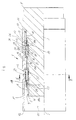
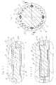
- FIGS. 1 to 6 show the longitudinal displacement unit in the retracted position of the two shaft elements 3, 11 to each other. All components of the longitudinal displacement unit 1 are centered on the longitudinal axis 2.
- the longitudinal displacement unit 1 comprises a first shaft element 3, the opposite end is the first free end fifth
- the first shaft element 3 has an outer surface 6, in which circumferentially distributed around the longitudinal axis 2 parallel to the longitudinal axis extending first grooves 7 are incorporated, which are limited for example by a circular arc radius.
- the first grooves 7 each end in a groove outlet 8, in which the bottom of the first grooves 7 approaches the outer surface 6.
- a first stop 9 in the form of a ring seated on a step surface is shown, which is held on this step surface by a securing ring which engages in a groove of the first shaft element 3.
- the ring forming the first stop 9 is designed with a diameter such that its outer diameter extends into the region of the first grooves 7.
- a circumferential groove is cut into the outer surface 6 of the first shaft element 3 interrupted by the first grooves 7, into which a securing ring or the like element is inserted as a second stop 10, this also protrudes in the cross section of the first shaft member 3 seen in the first grooves 7.
- the first shaft member 3 is received in a throughbore 15 of a second shaft member 11 which is a second terminal end 12 for connection to a second universal joint member and the second terminal end 12 has a second free end 13.
- the illustrated truncated state of the longitudinal displacement unit, i. the greatest possible insertion position of the two shaft elements 3, 11 to each other, the second free end 13 is approximated to the first terminal end 4 and correspondingly approximates the first free end 5 of the second terminal end 12.
- the through hole 15 forms an inner surface 14, are incorporated in the second grooves 16 parallel to the longitudinal axis 2 extending such that they each face a corresponding first groove 7. In each case a first groove 7 and a second groove 16 form a pair.
- the second shaft member 11 is associated with a third stop, which is also designed as a kind of locking ring and is seated in a groove which intersects the second grooves 16.
- This third stop 17 is arranged toward the second free end 13 at the end of the second grooves 16.
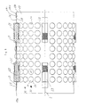
- a cage 19 In the radial clearance between the inner surface 14 of the second shaft member 11 and the outer surface 6 of the first shaft member 3 is a cage 19, the closer in FIG. 6 is shown.
- This cage 19 has in the direction of the first free end 5 and second terminal end 12 toward a first cage end 19a and at the opposite end to the first terminal end 14 and the second free end 13 indicative second cage 19b.
- the cage 19 is sleeve-shaped and has, corresponding to the pairs of first grooves 7 in the first shaft member 3 and opposite second grooves 16 in the second shaft member 11 circumferentially distributed rows of windows 20, which are each spaced apart per row along the longitudinal axis 2 from each other and each for receiving one Ball serve as rolling elements 21 which engage with their inwardly projecting beyond the cage inner surface 19d area in each case in a first groove 7 and with their respective over the cage outer surface 19c region in a second groove 16 in the second shaft member.
- the rolling elements 21 designed as balls are guided through the cage 19 and serve to transmit torque between the first shaft element 3 and the second shaft element 11.
- the cage 19 furthermore extends parallel to the longitudinal axis 2 and extends one behind the other along the longitudinal axis 2 a first elongated aperture 23 and a second elongate aperture 26 spaced from one another.
- the first opening 23 terminates in the direction of the first cage end 19a with the first longitudinal end 24 and remote with the second longitudinal end 25.
- the second aperture 26 terminates corresponding to the second cage end 19b close to the fourth longitudinal end 28 and this, ie close to the first breakthrough 23 with the third longitudinal end 27.
- four such pairs of first openings 23 and second openings 26 are arranged in the present embodiment. However, correspondingly fewer or more pairs of apertures or even rollers may be provided as rolling elements.
- each breakthrough 23, 24 serves to receive a unit, each comprising a compression spring 38. It is possible to provide only compression springs 38 in the breakthroughs or to make the support at the longitudinal ends cheaper because of the loading by the stops, the compression springs each assign a guide member 29.
- the guide element 29 comprises a guide pin 30 which has a head 31. From the guide pin 30 away, the head 31 has a head surface 32 and the guide pin 30 towards an annular surface 33. On the guide pin 30, a guide sleeve 34 is guided with its bore 35.
- the guide sleeve 34 has the guide pin 30 toward a first end face 36 and this facing away from a second End face 37.
- the compression spring 38 which is designed as a helical compression spring, received and is supported with its one end against the annular surface 33 and with its other end against the first end face 26 of the guide sleeve 34.
- the guide member 29 and the compression spring 38 are dimensioned so that the guide member 29 is received with the compression spring 38 in each case in one of the openings 23, 26 so with bias that the top surface 32 with respect to the first opening 23 at the first longitudinal end 24 and with respect of the second aperture 26 is supported at the third longitudinal end 27.
- the guide sleeve 34 is supported with its second end face 37 with respect to the first opening 23 at the second longitudinal end 25 and with respect to the second opening 26 at the fourth longitudinal end 28. This training is the same for all other distributed on the circumference of the cage 19 trained breakthroughs.
- the guide elements initially again assume such a position, in which the second end faces 37 of the guide sleeves are again supported on the corresponding longitudinal ends of the two openings 23, 26.
- the third stop 17 and the fourth stop 18 are arranged at a distance B to each other, which is also greater than the length L than that between the outer balls of a row of balls. From this, the free paths can be seen, via which an adjustment of the first shaft member 3 can be made to the second shaft member 11 without the guide elements 29 come into action, so that an adjustment of the cage 19 between the two shaft elements 3 and 11 is carried out under rolling friction.
- the guide elements 29 are positioned favorably between the first shaft element 3 and the second shaft element 11, a simplified embodiment for the guide elements 29 is also possible.
- a first modified embodiment is in the FIG. 7 shown.
- the guide member 129 is reduced to two guide pins 130, 130a, each having a head 131 and 131a each having a head face 132, 132a for support at the longitudinal ends of the apertures or for the support of the compression spring 138 facing this form an annular surface 133, 133a.
- the guide pins 130, 130a each engage in the bore formed by the compression spring 138 designed as a spiral spring.
- FIG. 8 Another simplified embodiment according to FIG. 8 provides only guide elements 229 in the form of guide pins 230, 230a, which practically the head in the embodiment according to FIG. 7 replace and each represent surfaces 39, 39a for support at the ends of the compression spring or at the longitudinal ends of the two openings 23, 36.
Landscapes
- Engineering & Computer Science (AREA)
- General Engineering & Computer Science (AREA)
- Mechanical Engineering (AREA)
- Ocean & Marine Engineering (AREA)
- Bearings For Parts Moving Linearly (AREA)
- Support Of The Bearing (AREA)
- Transmission Devices (AREA)
- Preliminary Treatment Of Fibers (AREA)
- Springs (AREA)
Applications Claiming Priority (1)
| Application Number | Priority Date | Filing Date | Title |
|---|---|---|---|
| DE102007007151A DE102007007151B4 (de) | 2007-02-09 | 2007-02-09 | Längsverschiebeeinheit für Gelenkwellen |
Publications (3)
| Publication Number | Publication Date |
|---|---|
| EP1956252A1 true EP1956252A1 (fr) | 2008-08-13 |
| EP1956252B1 EP1956252B1 (fr) | 2010-01-20 |
| EP1956252B8 EP1956252B8 (fr) | 2010-03-10 |
Family
ID=38924500
Family Applications (1)
| Application Number | Title | Priority Date | Filing Date |
|---|---|---|---|
| EP07021360A Not-in-force EP1956252B8 (fr) | 2007-02-09 | 2007-11-02 | Unité de déplacement longitudinal pour arbres de transmission |
Country Status (7)
| Country | Link |
|---|---|
| US (1) | US7922592B2 (fr) |
| EP (1) | EP1956252B8 (fr) |
| KR (1) | KR20080074765A (fr) |
| CN (1) | CN101240814B (fr) |
| AT (1) | ATE455966T1 (fr) |
| DE (1) | DE102007007151B4 (fr) |
| ES (1) | ES2338926T3 (fr) |
Families Citing this family (4)
| Publication number | Priority date | Publication date | Assignee | Title |
|---|---|---|---|---|
| US9355524B2 (en) * | 2008-09-19 | 2016-05-31 | Konami Gaming, Inc. | Gaming machine displaying selected symbols in cells |
| DE102017209167A1 (de) * | 2017-05-31 | 2018-12-06 | Thyssenkrupp Ag | Lenkwelle für ein Kraftfahrzeug |
| KR200496987Y1 (ko) * | 2021-05-11 | 2023-06-28 | 주식회사 고려농기 | 농기계 유니버설 조인트용 고정핀 |
| US12146526B2 (en) * | 2021-11-15 | 2024-11-19 | Steering Solutions Ip Holding Corporation | Ballspline shaft with no ball retainer |
Citations (5)
| Publication number | Priority date | Publication date | Assignee | Title |
|---|---|---|---|---|
| FR1373752A (fr) | 1963-08-12 | 1964-10-02 | Glaenzer Spicer Sa | Dispositif de coulissement pour transmission d'un couple, à corps de roulement et ressorts de localisation de ces derniers |
| US3279218A (en) * | 1964-05-11 | 1966-10-18 | Rockwell Standard Co | Extensible drive connections |
| GB1372402A (en) | 1971-12-22 | 1974-10-30 | Rotax Ltd | Ball splines |
| US20010018369A1 (en) * | 2000-02-24 | 2001-08-30 | Herbert Cermak | Plunging assembly for a driveshaft |
| WO2006048029A1 (fr) | 2004-10-29 | 2006-05-11 | Gkn Driveline International Gmbh | Unite de deplacement longitudinal a positionnement axial de la cage |
Family Cites Families (5)
| Publication number | Priority date | Publication date | Assignee | Title |
|---|---|---|---|---|
| DE2532674C3 (de) * | 1975-07-22 | 1979-10-25 | Jean Walterscheid Gmbh, 5204 Lohmar | Längenverstellbare Gelenkwelle |
| US4981459A (en) | 1989-05-30 | 1991-01-01 | Dana Corporation | Anti-lock ball spline assembly |
| DE10233758B4 (de) * | 2002-07-25 | 2004-07-29 | Gkn Driveline Deutschland Gmbh | Längsverschiebeeinheit mit Bremsrollen |
| GB2411930B (en) * | 2004-03-08 | 2007-10-17 | Ford Global Tech Llc | Driveshaft plunging units |
| CN100429413C (zh) * | 2006-01-10 | 2008-10-29 | 宁波恒力汽配轴承有限公司 | 自调整直线轴承及其加工方法 |
-
2007
- 2007-02-09 DE DE102007007151A patent/DE102007007151B4/de active Active
- 2007-11-02 ES ES07021360T patent/ES2338926T3/es active Active
- 2007-11-02 AT AT07021360T patent/ATE455966T1/de active
- 2007-11-02 EP EP07021360A patent/EP1956252B8/fr not_active Not-in-force
-
2008
- 2008-02-01 US US12/012,372 patent/US7922592B2/en active Active
- 2008-02-04 CN CN2008100058596A patent/CN101240814B/zh not_active Expired - Fee Related
- 2008-02-05 KR KR1020080011458A patent/KR20080074765A/ko not_active Ceased
Patent Citations (5)
| Publication number | Priority date | Publication date | Assignee | Title |
|---|---|---|---|---|
| FR1373752A (fr) | 1963-08-12 | 1964-10-02 | Glaenzer Spicer Sa | Dispositif de coulissement pour transmission d'un couple, à corps de roulement et ressorts de localisation de ces derniers |
| US3279218A (en) * | 1964-05-11 | 1966-10-18 | Rockwell Standard Co | Extensible drive connections |
| GB1372402A (en) | 1971-12-22 | 1974-10-30 | Rotax Ltd | Ball splines |
| US20010018369A1 (en) * | 2000-02-24 | 2001-08-30 | Herbert Cermak | Plunging assembly for a driveshaft |
| WO2006048029A1 (fr) | 2004-10-29 | 2006-05-11 | Gkn Driveline International Gmbh | Unite de deplacement longitudinal a positionnement axial de la cage |
Also Published As
| Publication number | Publication date |
|---|---|
| DE102007007151B4 (de) | 2009-01-02 |
| EP1956252B8 (fr) | 2010-03-10 |
| KR20080074765A (ko) | 2008-08-13 |
| ATE455966T1 (de) | 2010-02-15 |
| CN101240814A (zh) | 2008-08-13 |
| EP1956252B1 (fr) | 2010-01-20 |
| US7922592B2 (en) | 2011-04-12 |
| DE102007007151A1 (de) | 2008-08-14 |
| US20080194343A1 (en) | 2008-08-14 |
| ES2338926T3 (es) | 2010-05-13 |
| CN101240814B (zh) | 2010-06-02 |
Similar Documents
| Publication | Publication Date | Title |
|---|---|---|
| EP2877100A1 (fr) | Tige pour instrument médical comprenant des sections mobiles | |
| EP1411871A1 (fr) | Element d'ecartement de longueur axiale modifiable | |
| DE102015102183B4 (de) | Lenkzwischenwelle für ein Kraftfahrzeug und Verfahren zum Betreiben einer Lenkzwischenwelle für ein Kraftfahrzeug | |
| DE2020847B2 (de) | Federnder sicherungsring fuer radiale montage | |
| EP2766620B1 (fr) | Système de guidage télescopique | |
| WO2014166833A1 (fr) | Dispositif de réglage longitudinal d'un siège de véhicule et siège de véhicule | |
| EP2781309A2 (fr) | Clé universelle | |
| DE3629068C2 (fr) | ||
| DE102005034063B3 (de) | Vorrichtung zum Verschließen von Gebäudeöffnungen | |
| DE10301082B4 (de) | Wälzlager für Linearbewegungen | |
| DE2620334A1 (de) | Selbsttaetig gefuehrter axialer rohrkompensator | |
| EP1956252B1 (fr) | Unité de déplacement longitudinal pour arbres de transmission | |
| DE2852510A1 (de) | Vorrichtung zum kuppeln von wickelstaeben | |
| WO2016207132A1 (fr) | Chaîne porte-câbles | |
| EP0789986B1 (fr) | Bielle de relevage pour accouplement à trois points de tracteur | |
| DE19980346B4 (de) | Insbesondere Linear wirkendes Klemmgesperre | |
| EP2266721A2 (fr) | Mandrin doté de moyens d'alignement | |
| EP0208979A1 (fr) | Sécurité contre la surcharge | |
| EP3838669A1 (fr) | Barre de verrouillage à installer dans un espace de chargement d'un véhicule | |
| DE102011052747A1 (de) | Spannelement für eine Spannvorrichtung | |
| EP3625416B1 (fr) | Ensemble ressort pour un support de volet | |
| EP3106421A1 (fr) | Tige de telescope | |
| DE2908029B2 (de) | Dreiteilige auseinanderziehbare Teleskopwelle zur Übertragung von Drehmomenten | |
| EP3623251A1 (fr) | Dispositif stabilisateur pour véhicules ferroviaires, en particulier stabilisateur de roulis | |
| DE3916748C2 (fr) |
Legal Events
| Date | Code | Title | Description |
|---|---|---|---|
| PUAI | Public reference made under article 153(3) epc to a published international application that has entered the european phase |
Free format text: ORIGINAL CODE: 0009012 |
|
| AK | Designated contracting states |
Kind code of ref document: A1 Designated state(s): AT BE BG CH CY CZ DE DK EE ES FI FR GB GR HU IE IS IT LI LT LU LV MC MT NL PL PT RO SE SI SK TR |
|
| AX | Request for extension of the european patent |
Extension state: AL BA HR MK RS |
|
| 17P | Request for examination filed |
Effective date: 20081204 |
|
| 17Q | First examination report despatched |
Effective date: 20090113 |
|
| AKX | Designation fees paid |
Designated state(s): AT BE BG CH CY CZ DE DK EE ES FI FR GB GR HU IE IS IT LI LT LU LV MC MT NL PL PT RO SE SI SK TR |
|
| GRAP | Despatch of communication of intention to grant a patent |
Free format text: ORIGINAL CODE: EPIDOSNIGR1 |
|
| GRAS | Grant fee paid |
Free format text: ORIGINAL CODE: EPIDOSNIGR3 |
|
| GRAA | (expected) grant |
Free format text: ORIGINAL CODE: 0009210 |
|
| AK | Designated contracting states |
Kind code of ref document: B1 Designated state(s): AT BE BG CH CY CZ DE DK EE ES FI FR GB GR HU IE IS IT LI LT LU LV MC MT NL PL PT RO SE SI SK TR |
|
| REG | Reference to a national code |
Ref country code: GB Ref legal event code: FG4D Free format text: NOT ENGLISH |
|
| REG | Reference to a national code |
Ref country code: CH Ref legal event code: EP |
|
| RBV | Designated contracting states (corrected) |
Designated state(s): AT BE BG CH CY CZ DK EE ES FI FR GB GR HU IE IS IT LI LT LU LV MC MT NL PL PT RO SE SI SK TR |
|
| REG | Reference to a national code |
Ref country code: IE Ref legal event code: FG4D |
|
| REG | Reference to a national code |
Ref country code: NL Ref legal event code: T3 |
|
| REG | Reference to a national code |
Ref country code: ES Ref legal event code: FG2A Ref document number: 2338926 Country of ref document: ES Kind code of ref document: T3 |
|
| LTIE | Lt: invalidation of european patent or patent extension |
Effective date: 20100120 |
|
| PG25 | Lapsed in a contracting state [announced via postgrant information from national office to epo] |
Ref country code: LT Free format text: LAPSE BECAUSE OF FAILURE TO SUBMIT A TRANSLATION OF THE DESCRIPTION OR TO PAY THE FEE WITHIN THE PRESCRIBED TIME-LIMIT Effective date: 20100120 Ref country code: PT Free format text: LAPSE BECAUSE OF FAILURE TO SUBMIT A TRANSLATION OF THE DESCRIPTION OR TO PAY THE FEE WITHIN THE PRESCRIBED TIME-LIMIT Effective date: 20100520 Ref country code: IS Free format text: LAPSE BECAUSE OF FAILURE TO SUBMIT A TRANSLATION OF THE DESCRIPTION OR TO PAY THE FEE WITHIN THE PRESCRIBED TIME-LIMIT Effective date: 20100520 |
|
| REG | Reference to a national code |
Ref country code: IE Ref legal event code: FD4D |
|
| PG25 | Lapsed in a contracting state [announced via postgrant information from national office to epo] |
Ref country code: PL Free format text: LAPSE BECAUSE OF FAILURE TO SUBMIT A TRANSLATION OF THE DESCRIPTION OR TO PAY THE FEE WITHIN THE PRESCRIBED TIME-LIMIT Effective date: 20100120 Ref country code: LV Free format text: LAPSE BECAUSE OF FAILURE TO SUBMIT A TRANSLATION OF THE DESCRIPTION OR TO PAY THE FEE WITHIN THE PRESCRIBED TIME-LIMIT Effective date: 20100120 Ref country code: FI Free format text: LAPSE BECAUSE OF FAILURE TO SUBMIT A TRANSLATION OF THE DESCRIPTION OR TO PAY THE FEE WITHIN THE PRESCRIBED TIME-LIMIT Effective date: 20100120 Ref country code: SI Free format text: LAPSE BECAUSE OF FAILURE TO SUBMIT A TRANSLATION OF THE DESCRIPTION OR TO PAY THE FEE WITHIN THE PRESCRIBED TIME-LIMIT Effective date: 20100120 |
|
| PG25 | Lapsed in a contracting state [announced via postgrant information from national office to epo] |
Ref country code: EE Free format text: LAPSE BECAUSE OF FAILURE TO SUBMIT A TRANSLATION OF THE DESCRIPTION OR TO PAY THE FEE WITHIN THE PRESCRIBED TIME-LIMIT Effective date: 20100120 Ref country code: GR Free format text: LAPSE BECAUSE OF FAILURE TO SUBMIT A TRANSLATION OF THE DESCRIPTION OR TO PAY THE FEE WITHIN THE PRESCRIBED TIME-LIMIT Effective date: 20100421 Ref country code: IE Free format text: LAPSE BECAUSE OF FAILURE TO SUBMIT A TRANSLATION OF THE DESCRIPTION OR TO PAY THE FEE WITHIN THE PRESCRIBED TIME-LIMIT Effective date: 20100120 Ref country code: RO Free format text: LAPSE BECAUSE OF FAILURE TO SUBMIT A TRANSLATION OF THE DESCRIPTION OR TO PAY THE FEE WITHIN THE PRESCRIBED TIME-LIMIT Effective date: 20100120 Ref country code: SE Free format text: LAPSE BECAUSE OF FAILURE TO SUBMIT A TRANSLATION OF THE DESCRIPTION OR TO PAY THE FEE WITHIN THE PRESCRIBED TIME-LIMIT Effective date: 20100120 Ref country code: CY Free format text: LAPSE BECAUSE OF FAILURE TO SUBMIT A TRANSLATION OF THE DESCRIPTION OR TO PAY THE FEE WITHIN THE PRESCRIBED TIME-LIMIT Effective date: 20100120 |
|
| PLBE | No opposition filed within time limit |
Free format text: ORIGINAL CODE: 0009261 |
|
| STAA | Information on the status of an ep patent application or granted ep patent |
Free format text: STATUS: NO OPPOSITION FILED WITHIN TIME LIMIT |
|
| PG25 | Lapsed in a contracting state [announced via postgrant information from national office to epo] |
Ref country code: CZ Free format text: LAPSE BECAUSE OF FAILURE TO SUBMIT A TRANSLATION OF THE DESCRIPTION OR TO PAY THE FEE WITHIN THE PRESCRIBED TIME-LIMIT Effective date: 20100120 Ref country code: BG Free format text: LAPSE BECAUSE OF FAILURE TO SUBMIT A TRANSLATION OF THE DESCRIPTION OR TO PAY THE FEE WITHIN THE PRESCRIBED TIME-LIMIT Effective date: 20100420 Ref country code: SK Free format text: LAPSE BECAUSE OF FAILURE TO SUBMIT A TRANSLATION OF THE DESCRIPTION OR TO PAY THE FEE WITHIN THE PRESCRIBED TIME-LIMIT Effective date: 20100120 |
|
| 26N | No opposition filed |
Effective date: 20101021 |
|
| PG25 | Lapsed in a contracting state [announced via postgrant information from national office to epo] |
Ref country code: DK Free format text: LAPSE BECAUSE OF FAILURE TO SUBMIT A TRANSLATION OF THE DESCRIPTION OR TO PAY THE FEE WITHIN THE PRESCRIBED TIME-LIMIT Effective date: 20100120 |
|
| PG25 | Lapsed in a contracting state [announced via postgrant information from national office to epo] |
Ref country code: MC Free format text: LAPSE BECAUSE OF NON-PAYMENT OF DUE FEES Effective date: 20101130 |
|
| PG25 | Lapsed in a contracting state [announced via postgrant information from national office to epo] |
Ref country code: MT Free format text: LAPSE BECAUSE OF FAILURE TO SUBMIT A TRANSLATION OF THE DESCRIPTION OR TO PAY THE FEE WITHIN THE PRESCRIBED TIME-LIMIT Effective date: 20100120 Ref country code: IT Free format text: LAPSE BECAUSE OF NON-PAYMENT OF DUE FEES Effective date: 20101102 |
|
| REG | Reference to a national code |
Ref country code: CH Ref legal event code: PL |
|
| PG25 | Lapsed in a contracting state [announced via postgrant information from national office to epo] |
Ref country code: LI Free format text: LAPSE BECAUSE OF NON-PAYMENT OF DUE FEES Effective date: 20111130 Ref country code: CH Free format text: LAPSE BECAUSE OF NON-PAYMENT OF DUE FEES Effective date: 20111130 |
|
| PG25 | Lapsed in a contracting state [announced via postgrant information from national office to epo] |
Ref country code: LU Free format text: LAPSE BECAUSE OF NON-PAYMENT OF DUE FEES Effective date: 20101102 Ref country code: HU Free format text: LAPSE BECAUSE OF FAILURE TO SUBMIT A TRANSLATION OF THE DESCRIPTION OR TO PAY THE FEE WITHIN THE PRESCRIBED TIME-LIMIT Effective date: 20100721 |
|
| PG25 | Lapsed in a contracting state [announced via postgrant information from national office to epo] |
Ref country code: TR Free format text: LAPSE BECAUSE OF FAILURE TO SUBMIT A TRANSLATION OF THE DESCRIPTION OR TO PAY THE FEE WITHIN THE PRESCRIBED TIME-LIMIT Effective date: 20100120 |
|
| REG | Reference to a national code |
Ref country code: AT Ref legal event code: MM01 Ref document number: 455966 Country of ref document: AT Kind code of ref document: T Effective date: 20121130 |
|
| PG25 | Lapsed in a contracting state [announced via postgrant information from national office to epo] |
Ref country code: AT Free format text: LAPSE BECAUSE OF NON-PAYMENT OF DUE FEES Effective date: 20121130 |
|
| REG | Reference to a national code |
Ref country code: FR Ref legal event code: PLFP Year of fee payment: 9 |
|
| REG | Reference to a national code |
Ref country code: FR Ref legal event code: PLFP Year of fee payment: 10 |
|
| REG | Reference to a national code |
Ref country code: FR Ref legal event code: PLFP Year of fee payment: 11 |
|
| PGFP | Annual fee paid to national office [announced via postgrant information from national office to epo] |
Ref country code: NL Payment date: 20191126 Year of fee payment: 13 |
|
| PGFP | Annual fee paid to national office [announced via postgrant information from national office to epo] |
Ref country code: ES Payment date: 20191202 Year of fee payment: 13 Ref country code: BE Payment date: 20191127 Year of fee payment: 13 Ref country code: IT Payment date: 20191125 Year of fee payment: 13 Ref country code: FR Payment date: 20191125 Year of fee payment: 13 |
|
| PGFP | Annual fee paid to national office [announced via postgrant information from national office to epo] |
Ref country code: GB Payment date: 20191127 Year of fee payment: 13 |
|
| REG | Reference to a national code |
Ref country code: NL Ref legal event code: MM Effective date: 20201201 |
|
| GBPC | Gb: european patent ceased through non-payment of renewal fee |
Effective date: 20201102 |
|
| REG | Reference to a national code |
Ref country code: BE Ref legal event code: MM Effective date: 20201130 |
|
| PG25 | Lapsed in a contracting state [announced via postgrant information from national office to epo] |
Ref country code: NL Free format text: LAPSE BECAUSE OF NON-PAYMENT OF DUE FEES Effective date: 20201201 |
|
| PG25 | Lapsed in a contracting state [announced via postgrant information from national office to epo] |
Ref country code: IT Free format text: LAPSE BECAUSE OF NON-PAYMENT OF DUE FEES Effective date: 20201102 Ref country code: FR Free format text: LAPSE BECAUSE OF NON-PAYMENT OF DUE FEES Effective date: 20201130 |
|
| PG25 | Lapsed in a contracting state [announced via postgrant information from national office to epo] |
Ref country code: GB Free format text: LAPSE BECAUSE OF NON-PAYMENT OF DUE FEES Effective date: 20201102 |
|
| REG | Reference to a national code |
Ref country code: ES Ref legal event code: FD2A Effective date: 20220131 |
|
| PG25 | Lapsed in a contracting state [announced via postgrant information from national office to epo] |
Ref country code: ES Free format text: LAPSE BECAUSE OF NON-PAYMENT OF DUE FEES Effective date: 20201103 |
|
| PG25 | Lapsed in a contracting state [announced via postgrant information from national office to epo] |
Ref country code: BE Free format text: LAPSE BECAUSE OF NON-PAYMENT OF DUE FEES Effective date: 20201130 |