EP1958909A1 - Notabschaltsystem für aufzug - Google Patents
Notabschaltsystem für aufzug Download PDFInfo
- Publication number
- EP1958909A1 EP1958909A1 EP05809757A EP05809757A EP1958909A1 EP 1958909 A1 EP1958909 A1 EP 1958909A1 EP 05809757 A EP05809757 A EP 05809757A EP 05809757 A EP05809757 A EP 05809757A EP 1958909 A1 EP1958909 A1 EP 1958909A1
- Authority
- EP
- European Patent Office
- Prior art keywords
- calculating unit
- command value
- result
- calculation
- signal processing
- Prior art date
- Legal status (The legal status is an assumption and is not a legal conclusion. Google has not performed a legal analysis and makes no representation as to the accuracy of the status listed.)
- Granted
Links
Images





Classifications
-
- B—PERFORMING OPERATIONS; TRANSPORTING
- B66—HOISTING; LIFTING; HAULING
- B66B—ELEVATORS; ESCALATORS OR MOVING WALKWAYS
- B66B5/00—Applications of checking, fault-correcting, or safety devices in elevators
- B66B5/02—Applications of checking, fault-correcting, or safety devices in elevators responsive to abnormal operating conditions
-
- B—PERFORMING OPERATIONS; TRANSPORTING
- B66—HOISTING; LIFTING; HAULING
- B66B—ELEVATORS; ESCALATORS OR MOVING WALKWAYS
- B66B1/00—Control systems of elevators in general
- B66B1/24—Control systems with regulation, i.e. with retroactive action, for influencing travelling speed, acceleration, or deceleration
- B66B1/28—Control systems with regulation, i.e. with retroactive action, for influencing travelling speed, acceleration, or deceleration electrical
- B66B1/32—Control systems with regulation, i.e. with retroactive action, for influencing travelling speed, acceleration, or deceleration electrical effective on braking devices, e.g. acting on electrically controlled brakes
-
- B—PERFORMING OPERATIONS; TRANSPORTING
- B66—HOISTING; LIFTING; HAULING
- B66B—ELEVATORS; ESCALATORS OR MOVING WALKWAYS
- B66B1/00—Control systems of elevators in general
- B66B1/34—Details, e.g. call counting devices, data transmission from car to control system, devices giving information to the control system
-
- B—PERFORMING OPERATIONS; TRANSPORTING
- B66—HOISTING; LIFTING; HAULING
- B66B—ELEVATORS; ESCALATORS OR MOVING WALKWAYS
- B66B5/00—Applications of checking, fault-correcting, or safety devices in elevators
- B66B5/0006—Monitoring devices or performance analysers
- B66B5/0018—Devices monitoring the operating condition of the elevator system
- B66B5/0031—Devices monitoring the operating condition of the elevator system for safety reasons
Definitions
- the present invention relates to an emergency stop system for an elevator, for braking a car going up and down in a shaft for an emergency stop.
- Patent Document 1 JP-A-07-157 211 .
- the conventional example has a problem in that the high reliability of a control system or a state sensor is not ensured, and therefore the control system or the state sensor cannot be adapted to a product.
- the present invention is devised to solve the problem as described above and has an object to provide an emergency stop system for an elevator, which compares two-or-more-system state sensors and control systems to detect a failure in the control systems or the state sensors without fail to stop braking force control at the occurrence of the failure or to use a normal system, thereby safely braking an elevator even at the occurrence of the failure to cause the elevator to make an emergency stop.
- An emergency stop system for an elevator includes: a state sensor for detecting an operation of a car; a brake device for braking the car; a brake controller for outputting a signal for operating the brake device based on a signal detected by the state sensor; and an uninterruptible power supply device for supplying electric power to the state sensor, the brake device, and the brake controller, in which: the brake controller includes: a signal processing/ calculating unit for calculating a deceleration of the car based on the signal detected by the state sensor; a command value calculating unit for calculating a command value for operating the brake device based on the deceleration of the car, which is calculated by the signal processing/calculating unit; and a power monitoring device for monitoring a state of the uninterruptible power supply device; and at least any one of the state sensor, the signal processing/calculating unit, and the command value calculating unit has a plurality of independent systems.
- the emergency stop system for an elevator detects a failure in a control system or a state sensor without fail through the comparison between the results output from multiple detection means and calculation means to stop braking force control or to use a normal system at the occurrence of a failure.
- the emergency stop system for an elevator has the effect of safely braking the elevator even at the occurrence of the failure to cause the elevator to make an emergency stop.
- FIG. 1 is a view illustrating a configuration of the emergency stop system for an elevator according to the first embodiment of the present invention.
- the same reference numeral denotes the same or equivalent part.
- a main rope 13 which connects a car 15 and a counterweight 14 is looped around a sheave 12.
- the sheave 12 is rotated by a hoisting machine 11 to move the main rope 13 and the car 15 and the counterweight 14, which are connected to the main rope 13, by a friction force between the sheave 12 and the main rope 13.
- a speed governor 16 is a device which pulls up a speed governor rope 17 moving in tandem therewith to operate a safety device to stop the car 15 when the car 15 is lowered at an excessively high speed.
- the speed governor 16 rotationally operates in tandem with the movement of the car 15.
- the emergency stop system for an elevator since the emergency stop system for an elevator has an object to control a deceleration, a speed, and a position of the car 15 according to determined target values, the emergency stop system for an elevator includes a state sensor for detecting a deceleration, a speed, or a position of a part moving in tandem with the car 15 or a load applied to the counterweight 14 or the car 15.
- the emergency stop system for an elevator according to the first embodiment has independent two-system encoders corresponding to a first speed governor encoder (first state sensor) 1 and a second speed governor encoder (second state sensor) 2, and estimates the movement of the car 15 based on the decelerations detected by the speed governor encoders or the like. Signals detected by the two-system speed governor encoders 1 and 2 are input to a brake controller 31.
- the brake controller 31 outputs signals for operating the brake to a first brake coil 23 and a second brake coil 24 based on the signals detected by the speed governor encoders 1 and 2.
- a so-called electromagnetic brake is supposed as a brake device.
- the brake device pushes braking members (first brake plunger 21 and second brake plunger 22) against a member to be braked (brake pulley 25) with an elastic force of an elastic member to brake the member to be braked with a friction force.
- the circuits first brake coil 23 and second brake coil 24
- an electromagnetic force acts on the braking members 21 and 22 in a direction reacting against the elastic force to separate the braking members 21 and 22 from the member to be braked 25.
- the brake device brakes the car 15 with the maximum braking force.
- Fig. 2 illustrates an example showing a configuration of the brake controller 31 of Fig 1 .
- the brake controller 31 includes a sensor signal processing unit 41 for processing the signals received from the speed governor encoders 1 and 2, a command calculating unit 42 for calculating command values based on the processed sensor signals to output the calculated command values to the brake coils 23 and 24, and a power monitoring device 43 for monitoring a state of an uninterruptible power supply device 32 to output a command according to the monitored state.
- each dotted arrow indicates the transfer of the signal, whereas each solid arrow indicates the power supply.
- FIG. 3 is a flowchart illustrating an operation of the brake controller of the emergency stop system for an elevator according to the first embodiment of the present invention.
- the brake controller 31 receives an emergency stop command signal from an elevator operating device such as a control board to start the operation based on the received signal (Step 101).
- the power monitoring device 43 monitors a state of electric power supplied from the uninterruptible power supply device 32 to the entire brake control system. When the supplied electric power is unstable, the power monitoring device 43 feeds a power fail signal for stopping the brake control to the command calculating unit 42 (Step 102).
- the sensor signal processing unit 41 calculates deceleration of the car based on the signals detected by the first speed governor encoder 1 and the second speed governor encoder 2.
- the sensor signal processing unit 41 has two-system signal processing/calculating units corresponding to a first signal processing/calculating unit 51 and a second signal processing/calculating unit 52, each independently performing a calculation.
- each of the signal processing/calculating units 51 and 52 calculates a state quantity of the elevator, such as the deceleration based on the signals obtained from the speed governor encoders 1 and 2. The results are compared in each of the calculating units to detect a malfunction of the encoder.
- Step 103 when a difference between the state quantity calculated by the two-system encoders 1 and 2 the state quantity calculated by the two-system encoder 2 is smaller than a predetermined value in the first signal processing/calculating unit 51, or is less than the predetermined value (first predetermined value), it can be determined that the both encoders 1 and 2 operate normally.
- the difference is larger than the predetermined value, or is equal to or larger than the predetermined value (first predetermined value)
- the state quantities of the elevator which are calculated by the signal processing/calculating units 51 and 52, respectively, are compared with each other to determine that the calculations are correct.
- the first signal processing/calculating unit 51 calculates the state quantities of the elevator, such as the decelerations based on the signals obtained from the speed governor encoders 1 and 2 to compare an average value of the state quantities with an average value of the state quantities of the elevator, which are calculated by the second signal processing/calculating unit 52.
- the second signal processing/calculating unit 52 calculates the state quantities of the elevator, such as the decelerations based on the signals obtained from the speed governor encoders 1 and 2 to compare an average value of the state quantities with an average value of the state quantities of the elevator, which are calculated by the first signal processing/calculating unit 51. Even in this case, when a difference between the state quantities calculated by the two-system signal processing/calculating units 51 and 52 is smaller than a predetermined value, or is less than the predetermined value (second predetermined value), it can be determined that the signal processing/calculating units 51 and 52 both operate normally. When the difference is larger than the predetermined value, or is equal to or larger than the predetermined value (second predetermined value), it can be determined that at least one of the signal processing/calculating units malfunctions (Step 104).
- the sensor signal processing unit 41 When it is determined that the speed governor encoders 1 and 2 and the signal processing/calculating units 51 and 52 all operate normally, the sensor signal processing unit 41 outputs, for example, the average value of the state quantities of the elevator, which are calculated by the first signal processing/calculating unit 41 and the second signal processing/calculating unit 52, respectively, to the command calculating unit 42. Processing of obtaining the average value in a plurality of systems is the same in the other processing or in a second embodiment. It should be noted that in some cases, any one of the state quantities of the elevator, which are calculated by the first signal processing/calculating unit 51 and the second signal processing/calculating unit 52, respectively, may be output to the command calculating unit 42. The same is applied to the other processing or the second embodiment. When it is determined that any of the speed governor encoders 1 and 2 and the signal processing/calculating units 51 and 52 does not operate normally, the sensor signal processing unit 41 feeds a detection fail signal for stopping the brake control to the command calculating unit 42.
- the command calculating unit 42 calculates a command value for operating the brake and gives commands to the brake and the power source.
- the command calculating unit has two-system command value calculating units corresponding to a first command value calculating unit 61 and a second command value calculating unit 62, each independently calculating the command value to be provided for the brake. If the detection fail signal or the power fail signal is not input to the command calculating unit 42, the command values each are calculated by the command value calculating units 61 and 62 based on the state qualities of the elevator. The command values calculated by the two command value calculating units are compared with each other to determine that the calculations in the command value calculating units are correct.
- Step 106 and 107 an average value of the each calculated brake operation commands is fed from the brake controller 31 to the brake device.
- the brake device is required to be controlled after the determination of a target value which can realize a deceleration which does not adversely affect a passenger in the car 15 and the elevator system, and when the brake controller 31 has information of the position of the car, is moderated within the range that avoids the car 15 from entering the end of a shaft.
- the brake coils 23 and 24 are de-energized. Further, a signal for stopping power feeding from the uninterruptible power supply device 32 is output to the uninterruptible power supply device 32 to shut off the power supply itself. As a result, it can be ensured that the car is prevented from entering the end of the shaft at a dangerous speed.
- the uninterruptible power supply device 32 can supply electric power even in an emergency and has power storage ability. When a normal power source is not available, the stored power is supplied. Moreover, if it is determined that the stored power is always used in an emergency, the amount of power supply for keeping the brake in a released state is limited. As a result, since the upper limit of a time period, in which the brake is in the released state, can be ensured, added safety is ensured.
- the brake controller 31 has a timer function. After an elapse of a given period of time, or when the deceleration after an elapse of a given period of time is smaller than a predetermined value, a brake command is output. In another method, the brake command is output when a speed becomes excessively high. In this case, as a cycle used for the timer function, the use of a clock cycle of a CPU or a quartz frequency is given.
- the brake coils 23 and 24 are de-energized or the power supply from the uninterruptible power supply device 32 is shut off based on the output signal from the command calculating unit 42.
- a command may be directly output from the power monitoring device 43 or the sensor signal processing unit 41 to effect de-energization or to shut off the power supply.
- the signals obtained by detecting the rotations of the speed governor 16 with the encoders 1 and 2 are used to calculate the deceleration of the car 15, but a signal obtained by detecting, with a sensor, another part moving in tandem with the car 15, for example, the amount of rotation of the sheave 12, the amount of feeding of the main rope 13, or the amount of upward/downward movement of the counterweight 14 or the car 15 illustrated in Fig. 1 may be used.
- a signal obtained by detecting a current or a voltage of a motor serving as a source of power with a sensor may be used.
- Independent two-or-more-system state sensors may be the combination of sensors in different forms (for example, speed governor encoder, hoisting machine encoder, car acceleration sensor, car position sensor and the like). The sensor has different characteristics in control depending on the position of detection. For example, when the sensor directly detects the movement of the car 15, the control for restraining the oscillation of the car 15 can be performed.
- the electromagnetic brake is supposed as the brake used for braking in this first embodiment, but other brakes such as a hydraulic brake may be used as long as the brake can change a torque.
- so-called PID control for calculating the command value from a proportional element, a time integration element, and a time differentiation element of a difference between the target value and the detected value may be used.
- the value to be detected is the deceleration
- highly accurate deceleration control can be expected according to the system. Since two command values are provided and only the switching between the two command values enables the highly-accurate deceleration control in the latter case, the latter case has an advantage in that the configuration is not complicated.
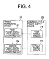
- the uninterrupted power source unit 32 includes independent two-system power sensors 71 and 72 and the power monitoring device 43 includes independent two-system power signal processing/calculating units 81 and 82 as illustrated in Fig. 4 and processing in the power monitoring device 43 is executed in the same sequence (in the same steps as Steps 103 and 104 of Fig. 3 ) as the sequence of the processing in the sensor signal processing unit 41, the detection of the stability of the power source can be ensured.
- FIG. 5 is a view illustrating a configuration of the emergency stop system for an elevator according to the second embodiment of the present invention.
- Fig. 5 the configuration of the emergency stop system for an elevator is obtained by adding a third speed governor encoder 3 to the configuration of the first embodiment described above.
- Fig. 6 is a block diagram illustrating the configuration of the brake controller of the emergency stop system for an elevator according to the second embodiment of the present invention.
- the role of the brake controller 31 is to control the braking force of the brake, which is the same as that in the first embodiment.
- the brake controller 31 includes the sensor signal processing unit 41 for processing the signals received from the first speed governor encoder 1, the second speed governor encoder 2, and the third speed governor encoder 3, the command calculating unit 42 for calculating and outputting the command value based on the processed sensor signals, and the power monitoring device 43 for monitoring the state of the uninterrupted power source unit 32 to output a command according to the monitored state.
- each dotted arrow indicates the transfer of a signal
- each solid arrow indicates the power supply.
- This second embodiment is characterized in that a third signal processing/calculating unit 53 is provided in the sensor signal processing unit 41 and a third command value calculating unit 63 is provided in the command calculating unit 42 in addition to the configuration in the first embodiment described above.
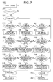
- FIG. 7 is a flowchart illustrating an operation of the brake controller of the emergency stop system for an elevator according to the second embodiment of the present invention.
- the operation of the brake controller in the determination of the emergency stop command (Step 201) and the determination of the safety of the power source (Step 202) is the same as the operation in the determination of the emergency stop command (Step 101 of Fig. 3 ) and in the determination of the safety of the power source (102 of Fig. 3 ) in the first embodiment.
- the sensor signal processing unit 41 calculates the deceleration of the car based on the signals detected by the speed governor encoders 1, 2, and 3.
- the sensor signal processing unit 41 has the three-system signal processing/calculating units 51, 52, and 53, each independently performing a calculation.
- each of the signal processing/calculating units 51, 52, and 53 calculates the state quantity of the elevator, such as the deceleration based on the signals obtained from the speed governor encoders 1, 2, and 3.
- the results are compared in each of the calculating units to detect a malfunction of the encoder. In the comparison, when a difference between the state quantities calculated by using the encoder signals from each two-system is smaller than the predetermined value, or is less than the predetermined value (first predetermined value), it is determined that both encoders operate normally.
- the encoder signals from the remaining two-system encoders can be used to perform control (Steps 203 to 208).
- the signals from the encoders which operate normally are used to calculate the necessary state quantities of the elevator in the signal processing/calculating units 51, 52, and 53.
- the results of the calculations are compared with each other to determine that the calculations in the signal processing/calculating units 51, 52, and 53 are correct. Even in this case, the comparison is performed between the results of the calculations of each two-system.
- a difference between the calculated state quantities is smaller than the predetermined value, or is less than the predetermined value (second predetermined value), it is determined that the signal processing/calculating units both operate normally.
- the difference is larger than the predetermined value, or is equal to or larger than the predetermined value (second predetermined value)
- the predetermined value second predetermined value
- Steps 215 to 220 when three-system command value calculating units are provided and compared with each other to confirm that the two-system command value calculating units operate normally in the command calculating unit 42, only the results of processing in the command value processing units which operate normally can be used to perform the control even if a failure occurs in the remaining one-system command value calculating unit (Steps 215 to 220).
- the sensor signal processing unit 41 outputs the state quantity of the elevator used for the control when two-or-more-system speed governor encoders of the speed governor encoders 1, 2, and 3 and two-or-more-system signal processing/calculating units of the signal processing/calculating units 51, 52, and 53 operate normally.
- the sensor signal processing unit 41 outputs the detection fail signal to the command calculating unit 42 when two-or-more-system speed governor encoders of the speed governor encoders 1, 2, and 3 or two-or-more-system signal processing/calculating units of the signal processing/calculating units 51, 52, and 53 malfunction.
- the uninterrupted power source unit 32 and the power monitoring device 43 For the uninterrupted power source unit 32 and the power monitoring device 43 , the following method may be used. Three-system power sensors 71, 72, and 73 and three-system power signal processing/calculating units 81, 82, and 83 are provided as illustrated in Fig. 8 . By performing the detection and the calculation with this configuration, the uninterrupted power source unit 32 and the power monitoring device 43 operate in the same manner as in the case where no failure occurs even when a failure occurs in one of the sensors or the calculating units, as in the case of the sensor signal processing unit 41 in the second embodiment.
- a method of operating the command calculating unit 42 by using only the results of processing in the calculating units which operate normally may be used even if a failure occurs in two-or-more-system calculating units.
- any of a method of using three-or-more-system sensors or the calculating units as described in this second embodiment and a method of using two-system sensors or calculating units as described in the first embodiment above can be selected in accordance with the degree of reliability of the sensors and the calculating units and the degree of safety required for the system.
- the brake is not forcibly stopped by the power shutoff without control as in the above-mentioned case where the electromagnetic brake is used, and the brake can be controlled at any time.
Landscapes
- Engineering & Computer Science (AREA)
- Automation & Control Theory (AREA)
- Computer Networks & Wireless Communication (AREA)
- Elevator Control (AREA)
- Indicating And Signalling Devices For Elevators (AREA)
- Maintenance And Inspection Apparatuses For Elevators (AREA)
Applications Claiming Priority (1)
| Application Number | Priority Date | Filing Date | Title |
|---|---|---|---|
| PCT/JP2005/021710 WO2007060733A1 (ja) | 2005-11-25 | 2005-11-25 | エレベーターの非常停止システム |
Publications (3)
| Publication Number | Publication Date |
|---|---|
| EP1958909A1 true EP1958909A1 (de) | 2008-08-20 |
| EP1958909A4 EP1958909A4 (de) | 2012-01-04 |
| EP1958909B1 EP1958909B1 (de) | 2014-01-08 |
Family
ID=38066975
Family Applications (1)
| Application Number | Title | Priority Date | Filing Date |
|---|---|---|---|
| EP05809757.7A Ceased EP1958909B1 (de) | 2005-11-25 | 2005-11-25 | Notabschaltsystem für aufzug |
Country Status (6)
| Country | Link |
|---|---|
| US (1) | US7918320B2 (de) |
| EP (1) | EP1958909B1 (de) |
| JP (1) | JP5079517B2 (de) |
| KR (1) | KR100995188B1 (de) |
| CN (1) | CN101312898B (de) |
| WO (1) | WO2007060733A1 (de) |
Cited By (4)
| Publication number | Priority date | Publication date | Assignee | Title |
|---|---|---|---|---|
| WO2010072714A1 (de) * | 2008-12-23 | 2010-07-01 | Inventio Ag | Aufzuganlage |
| EP2246285A4 (de) * | 2008-02-28 | 2014-07-16 | Mitsubishi Electric Corp | Aufzugssystem |
| EP2436635A4 (de) * | 2009-05-27 | 2015-06-10 | Mitsubishi Electric Corp | Aufzugsvorrichtung |
| RU2588327C2 (ru) * | 2012-01-25 | 2016-06-27 | Инвенцио Аг | Способ и устройство управления для контроля движения кабины лифта |
Families Citing this family (27)
| Publication number | Priority date | Publication date | Assignee | Title |
|---|---|---|---|---|
| KR100949238B1 (ko) * | 2006-03-02 | 2010-03-24 | 미쓰비시덴키 가부시키가이샤 | 엘리베이터 장치 |
| WO2007108068A1 (ja) * | 2006-03-17 | 2007-09-27 | Mitsubishi Denki Kabushiki Kaisha | エレベータ装置 |
| CN101268003B (zh) * | 2006-07-27 | 2010-08-18 | 三菱电机株式会社 | 电梯装置 |
| EP2141109A4 (de) * | 2007-04-26 | 2013-10-30 | Mitsubishi Electric Corp | Aufzugsvorrichtung |
| ES2499340T3 (es) * | 2007-08-07 | 2014-09-29 | Thyssenkrupp Elevator Ag | Sistema de elevador |
| JP5137508B2 (ja) * | 2007-09-11 | 2013-02-06 | 三菱電機ビルテクノサービス株式会社 | エレベータのかご保持装置 |
| US8365872B2 (en) | 2008-04-15 | 2013-02-05 | Mitsubishi Electric Corporation | Elevator device having the plurality of hoisting machines |
| EP2297017B2 (de) * | 2008-06-03 | 2024-12-04 | Otis Elevator Company | (elektrischer) einzelbremsbackentest für aufzüge |
| EP2287102B1 (de) * | 2008-06-20 | 2016-07-20 | Mitsubishi Electric Corporation | Aufzugsvorrichtung |
| BRPI0917293B1 (pt) * | 2008-08-18 | 2019-04-30 | Inventio Aktiengesellschaft | Processo e monitor de freio para monitorar um sistema de freio de um sistema de elevador e processo para reequipamento ou modernização de um sistema de elevador existente |
| JP5517432B2 (ja) * | 2008-10-16 | 2014-06-11 | 三菱電機株式会社 | エレベータ安全システム |
| WO2010058453A1 (ja) * | 2008-11-18 | 2010-05-27 | 三菱電機株式会社 | エレベータ装置 |
| JP5611937B2 (ja) * | 2009-03-13 | 2014-10-22 | 三菱電機株式会社 | エレベータ装置 |
| JPWO2010113356A1 (ja) * | 2009-04-03 | 2012-10-04 | 三菱電機株式会社 | エレベータ装置 |
| JP5360231B2 (ja) | 2009-12-15 | 2013-12-04 | 三菱電機株式会社 | エレベータ装置 |
| FI20105033A7 (fi) * | 2010-01-18 | 2011-07-19 | Kone Corp | Menetelmä hissikorin liikkeen valvomiseksi sekä hissijärjestelmä |
| US9637349B2 (en) | 2010-11-04 | 2017-05-02 | Otis Elevator Company | Elevator brake including coaxially aligned first and second brake members |
| CN102020158A (zh) * | 2010-11-29 | 2011-04-20 | 席尔诺智能互动科技(上海)有限公司 | 电梯停电自动放人系统 |
| JP5529075B2 (ja) * | 2011-05-25 | 2014-06-25 | 株式会社日立製作所 | エレベータ |
| US9708157B2 (en) * | 2012-02-03 | 2017-07-18 | Otis Elevator Company | Controlling speed of an elevator using a speed reducing switch and governor |
| FI123506B (fi) * | 2012-05-31 | 2013-06-14 | Kone Corp | Hissin käyttölaite sekä hissin turvajärjestely |
| JP6190171B2 (ja) * | 2013-06-10 | 2017-08-30 | 株式会社日立製作所 | エレベータ |
| JP6220613B2 (ja) * | 2013-09-19 | 2017-10-25 | 株式会社日立製作所 | エレベータの制御システム |
| JP6460920B2 (ja) * | 2015-06-12 | 2019-01-30 | 三菱電機株式会社 | エレベータの安全装置 |
| US9862568B2 (en) | 2016-02-26 | 2018-01-09 | Otis Elevator Company | Elevator run profile modification for smooth rescue |
| WO2023175856A1 (ja) * | 2022-03-17 | 2023-09-21 | 株式会社日立製作所 | エレベータ装置 |
| WO2025120747A1 (ja) * | 2023-12-05 | 2025-06-12 | 株式会社日立製作所 | エレベータ装置、並びにエレベータ装置の制御方法 |
Family Cites Families (19)
| Publication number | Priority date | Publication date | Assignee | Title |
|---|---|---|---|---|
| JPH0729746B2 (ja) | 1984-01-11 | 1995-04-05 | 株式会社日立製作所 | エレベ−タ−の非常停止制御装置 |
| US4750591A (en) * | 1987-07-10 | 1988-06-14 | Otis Elevator Company | Elevator car door and motion sequence monitoring apparatus and method |
| JPH0313467A (ja) | 1989-06-13 | 1991-01-22 | Mitsubishi Electric Corp | エレベータ用かご内負荷検出装置 |
| US5360952A (en) * | 1993-06-01 | 1994-11-01 | Otis Elevator Company | Local area network eleveator communications network |
| JPH07157211A (ja) | 1993-12-03 | 1995-06-20 | Mitsubishi Electric Corp | エレベーターのブレーキ装置 |
| JPH07206288A (ja) | 1994-01-14 | 1995-08-08 | Toshiba Corp | エレベーター |
| US6173814B1 (en) * | 1999-03-04 | 2001-01-16 | Otis Elevator Company | Electronic safety system for elevators having a dual redundant safety bus |
| US6196355B1 (en) * | 1999-03-26 | 2001-03-06 | Otis Elevator Company | Elevator rescue system |
| JP2002241062A (ja) | 2001-02-16 | 2002-08-28 | Mitsuru Takayama | エレベータ制御装置 |
| US6516922B2 (en) * | 2001-05-04 | 2003-02-11 | Gregory Shadkin | Self-generating elevator emergency power source |
| JP4647599B2 (ja) * | 2003-06-30 | 2011-03-09 | インベンテイオ・アクテイエンゲゼルシヤフト | エレベータ構造に対する安全システム |
| JP4475593B2 (ja) * | 2003-11-19 | 2010-06-09 | 三菱電機株式会社 | エレベータ制御装置 |
| US7334665B2 (en) * | 2004-03-02 | 2008-02-26 | Thyssenkrupp Elevator Capital Corporation | Interlock wiring communication system for elevators |
| JP4566587B2 (ja) * | 2004-03-17 | 2010-10-20 | 三菱電機株式会社 | エレベータの制御装置 |
| CN100406689C (zh) * | 2004-04-27 | 2008-07-30 | 三菱扶桑卡客车公司 | 内燃机的可变气门机构 |
| US7540358B2 (en) * | 2004-05-31 | 2009-06-02 | Mitsubishi Denki Kabushiki Kaisha | Elevator apparatus including main and auxiliary sensors |
| ATE361893T1 (de) * | 2005-03-05 | 2007-06-15 | Thyssenkrupp Aufzugswerke Gmbh | Aufzuganlage |
| FI118729B (fi) * | 2006-04-04 | 2008-02-29 | Kone Corp | Järjestely hissikorin pysäyttämiseksi hätäjarrutustilanteessa ja hissi |
| FI119508B (fi) * | 2007-04-03 | 2008-12-15 | Kone Corp | Vikaturvallinen tehonohjauslaitteisto |
-
2005
- 2005-11-25 WO PCT/JP2005/021710 patent/WO2007060733A1/ja not_active Ceased
- 2005-11-25 EP EP05809757.7A patent/EP1958909B1/de not_active Ceased
- 2005-11-25 JP JP2007546331A patent/JP5079517B2/ja not_active Expired - Fee Related
- 2005-11-25 KR KR1020087012395A patent/KR100995188B1/ko not_active Expired - Fee Related
- 2005-11-25 CN CN2005800521440A patent/CN101312898B/zh not_active Expired - Fee Related
- 2005-11-25 US US12/095,025 patent/US7918320B2/en not_active Expired - Fee Related
Cited By (7)
| Publication number | Priority date | Publication date | Assignee | Title |
|---|---|---|---|---|
| EP2246285A4 (de) * | 2008-02-28 | 2014-07-16 | Mitsubishi Electric Corp | Aufzugssystem |
| WO2010072714A1 (de) * | 2008-12-23 | 2010-07-01 | Inventio Ag | Aufzuganlage |
| CN102264622A (zh) * | 2008-12-23 | 2011-11-30 | 因温特奥股份公司 | 电梯设备 |
| CN102264622B (zh) * | 2008-12-23 | 2013-09-11 | 因温特奥股份公司 | 电梯设备 |
| US8813919B2 (en) | 2008-12-23 | 2014-08-26 | Inventio Ag | Elevator safety system preventing collision of cars |
| EP2436635A4 (de) * | 2009-05-27 | 2015-06-10 | Mitsubishi Electric Corp | Aufzugsvorrichtung |
| RU2588327C2 (ru) * | 2012-01-25 | 2016-06-27 | Инвенцио Аг | Способ и устройство управления для контроля движения кабины лифта |
Also Published As
| Publication number | Publication date |
|---|---|
| CN101312898A (zh) | 2008-11-26 |
| EP1958909A4 (de) | 2012-01-04 |
| KR100995188B1 (ko) | 2010-11-17 |
| WO2007060733A1 (ja) | 2007-05-31 |
| US20090266649A1 (en) | 2009-10-29 |
| JP5079517B2 (ja) | 2012-11-21 |
| EP1958909B1 (de) | 2014-01-08 |
| JPWO2007060733A1 (ja) | 2009-05-07 |
| CN101312898B (zh) | 2012-03-07 |
| US7918320B2 (en) | 2011-04-05 |
| KR20080059463A (ko) | 2008-06-27 |
Similar Documents
| Publication | Publication Date | Title |
|---|---|---|
| EP1958909B1 (de) | Notabschaltsystem für aufzug | |
| EP2399858B1 (de) | Bremsvorrichtung für aufzug | |
| AU2019204558B2 (en) | An Elevator | |
| JP7193341B2 (ja) | 準弾性的な解除端部ストッパーを使って電気的なアクチュエーターの確実な解除を行うための方法、及び装置 | |
| US8297411B2 (en) | Brake device for use in an elevator using a target pattern when a hoist is not driven | |
| US8272482B2 (en) | Elevator apparatus for braking control of car according to detected content of failure | |
| US7669697B2 (en) | Elevator apparatus | |
| EP1997765B1 (de) | Aufzugsvorrichtung | |
| EP2527281B1 (de) | Aufzug | |
| CN104909234B (zh) | 对垂直传送设备机械制动器的工作状况检测的方法和装置 | |
| EP2406163B2 (de) | Bremsmomentsteuerung | |
| EP1990305B1 (de) | Aufzugsvorrichtung | |
| CA2861399A1 (en) | Method and control device for monitoring travel movements of a lift cage | |
| CN100595122C (zh) | 电梯装置 | |
| JPH02100979A (ja) | エレベーターにおける荷重測定方法及び装置 | |
| EP2147883B1 (de) | Aufzugsvorrichtung | |
| EP3693310B1 (de) | Aktives bremsen für sofortstopps | |
| EP3053866B1 (de) | Aufzugsbremsauslöseüberwachung | |
| EP2765107B1 (de) | Aufzugsvorrichtung | |
| HK1167254B (en) | Brake torque control |
Legal Events
| Date | Code | Title | Description |
|---|---|---|---|
| PUAI | Public reference made under article 153(3) epc to a published international application that has entered the european phase |
Free format text: ORIGINAL CODE: 0009012 |
|
| 17P | Request for examination filed |
Effective date: 20080624 |
|
| AK | Designated contracting states |
Kind code of ref document: A1 Designated state(s): DE |
|
| DAX | Request for extension of the european patent (deleted) | ||
| RBV | Designated contracting states (corrected) |
Designated state(s): DE |
|
| A4 | Supplementary search report drawn up and despatched |
Effective date: 20111205 |
|
| RIC1 | Information provided on ipc code assigned before grant |
Ipc: B66B 5/02 20060101ALI20111129BHEP Ipc: B66B 1/32 20060101AFI20111129BHEP Ipc: B66B 1/34 20060101ALI20111129BHEP Ipc: B66B 5/00 20060101ALI20111129BHEP |
|
| GRAP | Despatch of communication of intention to grant a patent |
Free format text: ORIGINAL CODE: EPIDOSNIGR1 |
|
| INTG | Intention to grant announced |
Effective date: 20130718 |
|
| GRAS | Grant fee paid |
Free format text: ORIGINAL CODE: EPIDOSNIGR3 |
|
| GRAA | (expected) grant |
Free format text: ORIGINAL CODE: 0009210 |
|
| AK | Designated contracting states |
Kind code of ref document: B1 Designated state(s): DE |
|
| REG | Reference to a national code |
Ref country code: DE Ref legal event code: R096 Ref document number: 602005042451 Country of ref document: DE Effective date: 20140213 |
|
| REG | Reference to a national code |
Ref country code: DE Ref legal event code: R097 Ref document number: 602005042451 Country of ref document: DE |
|
| PLBE | No opposition filed within time limit |
Free format text: ORIGINAL CODE: 0009261 |
|
| STAA | Information on the status of an ep patent application or granted ep patent |
Free format text: STATUS: NO OPPOSITION FILED WITHIN TIME LIMIT |
|
| 26N | No opposition filed |
Effective date: 20141009 |
|
| REG | Reference to a national code |
Ref country code: DE Ref legal event code: R097 Ref document number: 602005042451 Country of ref document: DE Effective date: 20141009 |
|
| REG | Reference to a national code |
Ref country code: DE Ref legal event code: R084 Ref document number: 602005042451 Country of ref document: DE |
|
| PGFP | Annual fee paid to national office [announced via postgrant information from national office to epo] |
Ref country code: DE Payment date: 20210929 Year of fee payment: 17 |
|
| REG | Reference to a national code |
Ref country code: DE Ref legal event code: R119 Ref document number: 602005042451 Country of ref document: DE |
|
| PG25 | Lapsed in a contracting state [announced via postgrant information from national office to epo] |
Ref country code: DE Free format text: LAPSE BECAUSE OF NON-PAYMENT OF DUE FEES Effective date: 20230601 |