EP1959199A2 - Four doté d'une installation à micro-ondes - Google Patents
Four doté d'une installation à micro-ondes Download PDFInfo
- Publication number
- EP1959199A2 EP1959199A2 EP08101482A EP08101482A EP1959199A2 EP 1959199 A2 EP1959199 A2 EP 1959199A2 EP 08101482 A EP08101482 A EP 08101482A EP 08101482 A EP08101482 A EP 08101482A EP 1959199 A2 EP1959199 A2 EP 1959199A2
- Authority
- EP
- European Patent Office
- Prior art keywords
- ventilation
- cooking chamber
- blower
- baking oven
- fan
- Prior art date
- Legal status (The legal status is an assumption and is not a legal conclusion. Google has not performed a legal analysis and makes no representation as to the accuracy of the status listed.)
- Withdrawn
Links
- 238000009423 ventilation Methods 0.000 claims abstract description 41
- 238000010411 cooking Methods 0.000 claims abstract description 31
- 238000002485 combustion reaction Methods 0.000 abstract 1
- 238000001816 cooling Methods 0.000 description 4
- 238000000034 method Methods 0.000 description 4
- 238000009434 installation Methods 0.000 description 2
- 238000001514 detection method Methods 0.000 description 1
- 230000009977 dual effect Effects 0.000 description 1
- 230000007613 environmental effect Effects 0.000 description 1
- 238000000605 extraction Methods 0.000 description 1
- 230000017525 heat dissipation Effects 0.000 description 1
- 238000012423 maintenance Methods 0.000 description 1
- 239000000203 mixture Substances 0.000 description 1
Images
Classifications
-
- F—MECHANICAL ENGINEERING; LIGHTING; HEATING; WEAPONS; BLASTING
- F24—HEATING; RANGES; VENTILATING
- F24C—DOMESTIC STOVES OR RANGES ; DETAILS OF DOMESTIC STOVES OR RANGES, OF GENERAL APPLICATION
- F24C15/00—Details
- F24C15/20—Removing cooking fumes
- F24C15/2007—Removing cooking fumes from oven cavities
-
- F—MECHANICAL ENGINEERING; LIGHTING; HEATING; WEAPONS; BLASTING
- F24—HEATING; RANGES; VENTILATING
- F24C—DOMESTIC STOVES OR RANGES ; DETAILS OF DOMESTIC STOVES OR RANGES, OF GENERAL APPLICATION
- F24C15/00—Details
- F24C15/006—Arrangements for circulation of cooling air
-
- H—ELECTRICITY
- H05—ELECTRIC TECHNIQUES NOT OTHERWISE PROVIDED FOR
- H05B—ELECTRIC HEATING; ELECTRIC LIGHT SOURCES NOT OTHERWISE PROVIDED FOR; CIRCUIT ARRANGEMENTS FOR ELECTRIC LIGHT SOURCES, IN GENERAL
- H05B6/00—Heating by electric, magnetic or electromagnetic fields
- H05B6/64—Heating using microwaves
- H05B6/642—Cooling of the microwave components and related air circulation systems
Definitions
- the invention relates to an oven with a microwave device and optionally with a thermal heater for cooking food and with a ventilation system formed by fan and ventilation ducts for front discharge on the one hand, the operating heat from the microwave generator and on the other hand of vapors from the oven.
- a cooling fan on the suction side connected to an air duct on the rear panel, which air duct with fresh air from the front and from the far side of the device back, so in the case of a built-in furniture built-in oven from a mandatory air gap between the rear wall of the Built-in furniture and the rear of the appliance (see ventilation arrow in FIG. 1 the aforementioned document) is supplied.
- this cooling-air fan cools a magnetron of a microwave generator, with the heated air being discharged from the front.
- a further blower is provided, which from its environment as well as also from a required air space or air gap (see ventilation arrow in FIG.
- the present invention has the object of providing an oven of the type mentioned in such a way that with low equipment and in particular parts of a front ventilation of the ventilation system and thus installation of the oven is also possible in ventilation unfavorable kitchen furniture.
- a first blower suction side is connected to an inlet opening on the furnace front side and the pressure side and / or suction side of the ventilation of the microwave generator and the pressure side of the ventilation Garraumes serves that a second fan is on the suction side connected to the cooking chamber and optionally to the surrounding space fluidly and that at least the second blower pressure side opens into a ventilation duct, the mind. Leads to a blowout on the furnace front.
- the second fan is arranged in a central upper region of a space containing the microwave generator and electrical components for its control.
- This preferably designed as a cross-flow fan second fan has several functions. Due to its placement in the upper region of the ambient space of the oven or the cooking chamber can e.g. suction side of the detection and discharge of the heated air from this ambient space, e.g. from the thermally heavily loaded or heat-sensitive components containing so-called switch room, serve and on the other hand it provides for the extraction of e.g.
- the first blower flows on the pressure side downstream of the microwave generator and a ventilation inlet of the cooking chamber into a leading to the furnace front ventilation duct for a partial flow of the first blower.
- the first fan has a dual function, namely the heat dissipation from the range of the microwave generator with thermally heavily loaded magnetron and transformer as well as the ventilation of the cooking space.
- the cooking chamber on two opposite side walls flow openings for the inflowing and outflowing air, so that it can be spoken of a proper ventilation of the cooking chamber here. This also opens up the possibility of using a particularly powerful grill heater in the pure grill mode or in combination mode with grill and microwave, which is then cooled by the said ventilation of the cooking chamber to an appropriate grill temperature.
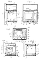
- the oven (1) is mounted in a box-shaped, completely indicated kitchen furniture (3) attached to a wall (2), whereby - clarified by circles - between the rear boundary of this kitchen unit (3) and the wall (2) no air gap remains through which fresh air could get to the oven (1).
- the oven (1) is in the FIGS. 3 to 5 shown together with parts of the kitchen cabinet (3) and is provided on the front of the oven with eg a hinged oven door (4) and on all other sides including the back in the usual way with walls, eg (5) of a furnace housing not shown in detail.
- Behind the oven door (4) is a cuboid cooking chamber (6), at its upper limit, an electric grill element (7) is located.
- a space (9) is provided within the furnace housing in addition to a side wall of the cooking chamber (6), in which at least a magnetron (10) and a high-frequency transformer (11) of a microwave generator (9/10) is located.
- This space (9) is frontally closed by a control element (eg 12) having front panel (13).
- a second designed as a cross-flow fan elongated blower (15), while in the space (9) formed a first, designed as an axial fan (16) located ( Figure 3.4 ).
- FIG. 3, 4 is discharged through the exhaust opening (20) at the front into the open air.
- blows the first fan (16) a partial flow of the process air through an inlet opening (24) in a cooking chamber side wall into the interior of the cooking chamber (6).
- This airflow optionally mixed with the hot vapors produced in the cooking or grilling operation and is supplied through an exhaust opening (25) on the opposite side wall of the suction side of the second blower (15) via a ventilation duct (26) and from there via a above the cooking chamber (6) lying ventilation duct (27) on the front side via a blow-out opening (28) discharged into the open (see FIG. 5 ).
- the last-mentioned blower (15) can at the same time discharge heated air, for example from a switch room (ambient space (29)) above the cooking chamber (6), through the blow-out opening (28) into the open air.
Landscapes
- Engineering & Computer Science (AREA)
- Chemical & Material Sciences (AREA)
- Combustion & Propulsion (AREA)
- Mechanical Engineering (AREA)
- General Engineering & Computer Science (AREA)
- Physics & Mathematics (AREA)
- Electromagnetism (AREA)
- Electric Ovens (AREA)
Applications Claiming Priority (1)
| Application Number | Priority Date | Filing Date | Title |
|---|---|---|---|
| DE102007007542A DE102007007542A1 (de) | 2007-02-15 | 2007-02-15 | Backofen mit einer Mikrowelleneinrichtung |
Publications (2)
| Publication Number | Publication Date |
|---|---|
| EP1959199A2 true EP1959199A2 (fr) | 2008-08-20 |
| EP1959199A3 EP1959199A3 (fr) | 2017-08-09 |
Family
ID=39415349
Family Applications (1)
| Application Number | Title | Priority Date | Filing Date |
|---|---|---|---|
| EP08101482.1A Withdrawn EP1959199A3 (fr) | 2007-02-15 | 2008-02-11 | Four doté d'une installation à micro-ondes |
Country Status (2)
| Country | Link |
|---|---|
| EP (1) | EP1959199A3 (fr) |
| DE (1) | DE102007007542A1 (fr) |
Families Citing this family (2)
| Publication number | Priority date | Publication date | Assignee | Title |
|---|---|---|---|---|
| DE102012217352A1 (de) | 2012-09-26 | 2014-03-27 | BSH Bosch und Siemens Hausgeräte GmbH | Haushaltsgerät mit einer Mikrowellenvorrichtung |
| DE202022104764U1 (de) | 2022-08-23 | 2023-11-24 | Topinox Sarl | Gargerät mit Kühlluftkanal |
Citations (1)
| Publication number | Priority date | Publication date | Assignee | Title |
|---|---|---|---|---|
| DE3839657C2 (de) | 1988-11-24 | 1993-11-18 | Miele & Cie | Luftführungssystem für einen Backofen |
Family Cites Families (3)
| Publication number | Priority date | Publication date | Assignee | Title |
|---|---|---|---|---|
| US4180049A (en) * | 1978-01-09 | 1979-12-25 | Whirlpool Corporation | Oven assembly air circulation system |
| US4184945A (en) * | 1978-06-12 | 1980-01-22 | Litton Systems, Inc. | Microwave wall oven air flow system |
| DE3346019C2 (de) * | 1983-12-20 | 1985-11-07 | Bosch-Siemens Hausgeraete Gmbh, 7000 Stuttgart | Backofen |
-
2007
- 2007-02-15 DE DE102007007542A patent/DE102007007542A1/de not_active Withdrawn
-
2008
- 2008-02-11 EP EP08101482.1A patent/EP1959199A3/fr not_active Withdrawn
Patent Citations (1)
| Publication number | Priority date | Publication date | Assignee | Title |
|---|---|---|---|---|
| DE3839657C2 (de) | 1988-11-24 | 1993-11-18 | Miele & Cie | Luftführungssystem für einen Backofen |
Also Published As
| Publication number | Publication date |
|---|---|
| DE102007007542A1 (de) | 2008-08-21 |
| EP1959199A3 (fr) | 2017-08-09 |
Similar Documents
| Publication | Publication Date | Title |
|---|---|---|
| DE60308134T2 (de) | Wandmontierter Mikrowellenherd | |
| DE69709058T2 (de) | Mikrowellenofen | |
| DE3839657C2 (de) | Luftführungssystem für einen Backofen | |
| DE3928572C2 (fr) | ||
| DE2825461A1 (de) | Doppelbackofen, insbesondere einbaubackofen | |
| EP1956302A2 (fr) | Agencement de porte de four doté d'un écran dissipateur de chaleur pour fenêtres de porte de four | |
| EP1816402B1 (fr) | Four | |
| DE2705395B2 (de) | Herd | |
| DE69211611T2 (de) | Kochgerät | |
| DE602004001323T2 (de) | Wandmontierter Mikrowellenofen | |
| EP2610557A1 (fr) | Four de cuisson avec chauffage de la sole et de l'air chaud | |
| DE3337313C2 (fr) | ||
| EP0671591A1 (fr) | Dispositif pour éliminer les buées d'un four | |
| DE102011006075B4 (de) | Gargerät mit Kühlluftführung | |
| EP1979683B1 (fr) | Porte d'appareil de cuisson | |
| DE60121127T2 (de) | Belüftungsstruktur bei einem Mikrowellenofen und die Lampenausrüstungstruktur dergleichen | |
| CH717980A1 (de) | Gargerät mit Kamera zur Überwachung des Garraums. | |
| DE102020121633B4 (de) | Induktionskochfeld | |
| EP1639299A1 (fr) | Four de cuisson | |
| EP1959199A2 (fr) | Four doté d'une installation à micro-ondes | |
| DE19504673C2 (de) | Einbaugargerät-Kühlung | |
| DE102004058196A1 (de) | Einbaukältegerät | |
| EP0003764B1 (fr) | Four de cuisson double, en particulier four de cuisson encastré | |
| DE2615604A1 (de) | Backofen, insbesondere mit mitteln zur pyrolytischen reinigung | |
| DE2947151C2 (de) | Backofen |
Legal Events
| Date | Code | Title | Description |
|---|---|---|---|
| PUAI | Public reference made under article 153(3) epc to a published international application that has entered the european phase |
Free format text: ORIGINAL CODE: 0009012 |
|
| AK | Designated contracting states |
Kind code of ref document: A2 Designated state(s): AT BE BG CH CY CZ DE DK EE ES FI FR GB GR HR HU IE IS IT LI LT LU LV MC MT NL NO PL PT RO SE SI SK TR |
|
| AX | Request for extension of the european patent |
Extension state: AL BA MK RS |
|
| RAP1 | Party data changed (applicant data changed or rights of an application transferred) |
Owner name: BSH HAUSGERAETE GMBH |
|
| PUAL | Search report despatched |
Free format text: ORIGINAL CODE: 0009013 |
|
| AK | Designated contracting states |
Kind code of ref document: A3 Designated state(s): AT BE BG CH CY CZ DE DK EE ES FI FR GB GR HR HU IE IS IT LI LT LU LV MC MT NL NO PL PT RO SE SI SK TR |
|
| AX | Request for extension of the european patent |
Extension state: AL BA MK RS |
|
| RIC1 | Information provided on ipc code assigned before grant |
Ipc: F24C 15/20 20060101ALI20170706BHEP Ipc: H05B 6/64 20060101AFI20170706BHEP Ipc: F24C 15/00 20060101ALI20170706BHEP |
|
| 17P | Request for examination filed |
Effective date: 20180209 |
|
| RBV | Designated contracting states (corrected) |
Designated state(s): AT BE BG CH CY CZ DE DK EE ES FI FR GB GR HR HU IE IS IT LI LT LU LV MC MT NL NO PL PT RO SE SI SK TR |
|
| AKX | Designation fees paid |
Designated state(s): AT BE BG CH CY CZ DE DK EE ES FI FR GB GR HR HU IE IS IT LI LT LU LV MC MT NL NO PL PT RO SE SI SK TR |
|
| AXX | Extension fees paid |
Extension state: MK Extension state: BA Extension state: RS Extension state: AL |
|
| STAA | Information on the status of an ep patent application or granted ep patent |
Free format text: STATUS: THE APPLICATION IS DEEMED TO BE WITHDRAWN |
|
| 18D | Application deemed to be withdrawn |
Effective date: 20190903 |