EP1960260B1 - Systeme d'entrainement hybride pour navire - Google Patents
Systeme d'entrainement hybride pour navire Download PDFInfo
- Publication number
- EP1960260B1 EP1960260B1 EP06807136.4A EP06807136A EP1960260B1 EP 1960260 B1 EP1960260 B1 EP 1960260B1 EP 06807136 A EP06807136 A EP 06807136A EP 1960260 B1 EP1960260 B1 EP 1960260B1
- Authority
- EP
- European Patent Office
- Prior art keywords
- generator
- converter
- drive unit
- propulsion system
- watercraft
- Prior art date
- Legal status (The legal status is an assumption and is not a legal conclusion. Google has not performed a legal analysis and makes no representation as to the accuracy of the status listed.)
- Not-in-force
Links
Images

Classifications
-
- B—PERFORMING OPERATIONS; TRANSPORTING
- B63—SHIPS OR OTHER WATERBORNE VESSELS; RELATED EQUIPMENT
- B63H—MARINE PROPULSION OR STEERING
- B63H23/00—Transmitting power from propulsion power plant to propulsive elements
- B63H23/22—Transmitting power from propulsion power plant to propulsive elements with non-mechanical gearing
- B63H23/24—Transmitting power from propulsion power plant to propulsive elements with non-mechanical gearing electric
-
- B—PERFORMING OPERATIONS; TRANSPORTING
- B63—SHIPS OR OTHER WATERBORNE VESSELS; RELATED EQUIPMENT
- B63H—MARINE PROPULSION OR STEERING
- B63H21/00—Use of propulsion power plant or units on vessels
- B63H21/20—Use of propulsion power plant or units on vessels the vessels being powered by combinations of different types of propulsion units
-
- B—PERFORMING OPERATIONS; TRANSPORTING
- B63—SHIPS OR OTHER WATERBORNE VESSELS; RELATED EQUIPMENT
- B63H—MARINE PROPULSION OR STEERING
- B63H3/00—Propeller-blade pitch changing
-
- B—PERFORMING OPERATIONS; TRANSPORTING
- B63—SHIPS OR OTHER WATERBORNE VESSELS; RELATED EQUIPMENT
- B63J—AUXILIARIES ON VESSELS
- B63J3/00—Driving of auxiliaries
-
- H—ELECTRICITY
- H02—GENERATION; CONVERSION OR DISTRIBUTION OF ELECTRIC POWER
- H02J—ELECTRIC POWER NETWORKS; CIRCUIT ARRANGEMENTS OR SYSTEMS FOR SUPPLYING OR DISTRIBUTING ELECTRIC POWER; SYSTEMS FOR STORING ELECTRIC ENERGY
- H02J3/00—Circuit arrangements for AC mains or AC distribution networks
-
- B—PERFORMING OPERATIONS; TRANSPORTING
- B63—SHIPS OR OTHER WATERBORNE VESSELS; RELATED EQUIPMENT
- B63H—MARINE PROPULSION OR STEERING
- B63H21/00—Use of propulsion power plant or units on vessels
- B63H21/20—Use of propulsion power plant or units on vessels the vessels being powered by combinations of different types of propulsion units
- B63H2021/202—Use of propulsion power plant or units on vessels the vessels being powered by combinations of different types of propulsion units of hybrid electric type
-
- B—PERFORMING OPERATIONS; TRANSPORTING
- B63—SHIPS OR OTHER WATERBORNE VESSELS; RELATED EQUIPMENT
- B63H—MARINE PROPULSION OR STEERING
- B63H21/00—Use of propulsion power plant or units on vessels
- B63H21/20—Use of propulsion power plant or units on vessels the vessels being powered by combinations of different types of propulsion units
- B63H2021/202—Use of propulsion power plant or units on vessels the vessels being powered by combinations of different types of propulsion units of hybrid electric type
- B63H2021/205—Use of propulsion power plant or units on vessels the vessels being powered by combinations of different types of propulsion units of hybrid electric type the second power unit being of the internal combustion engine type, or the like, e.g. a Diesel engine
-
- H—ELECTRICITY
- H02—GENERATION; CONVERSION OR DISTRIBUTION OF ELECTRIC POWER
- H02J—ELECTRIC POWER NETWORKS; CIRCUIT ARRANGEMENTS OR SYSTEMS FOR SUPPLYING OR DISTRIBUTING ELECTRIC POWER; SYSTEMS FOR STORING ELECTRIC ENERGY
- H02J2105/00—Networks for supplying or distributing electric power characterised by their spatial reach or by the load
- H02J2105/30—Networks for supplying or distributing electric power characterised by their spatial reach or by the load the load networks being external to vehicles, i.e. exchanging power with vehicles
- H02J2105/31—Networks for supplying or distributing electric power characterised by their spatial reach or by the load the load networks being external to vehicles, i.e. exchanging power with vehicles for ships or vessels
-
- H—ELECTRICITY
- H02—GENERATION; CONVERSION OR DISTRIBUTION OF ELECTRIC POWER
- H02J—ELECTRIC POWER NETWORKS; CIRCUIT ARRANGEMENTS OR SYSTEMS FOR SUPPLYING OR DISTRIBUTING ELECTRIC POWER; SYSTEMS FOR STORING ELECTRIC ENERGY
- H02J3/00—Circuit arrangements for AC mains or AC distribution networks
- H02J3/007—Arrangements for selectively connecting one or more loads to one or more power sources or power lines
-
- H—ELECTRICITY
- H02—GENERATION; CONVERSION OR DISTRIBUTION OF ELECTRIC POWER
- H02J—ELECTRIC POWER NETWORKS; CIRCUIT ARRANGEMENTS OR SYSTEMS FOR SUPPLYING OR DISTRIBUTING ELECTRIC POWER; SYSTEMS FOR STORING ELECTRIC ENERGY
- H02J4/00—Circuit arrangements for mains or distribution networks not specified as AC or DC; Circuit arrangements for mains or distribution networks combining AC and DC sections or sub-networks
-
- Y—GENERAL TAGGING OF NEW TECHNOLOGICAL DEVELOPMENTS; GENERAL TAGGING OF CROSS-SECTIONAL TECHNOLOGIES SPANNING OVER SEVERAL SECTIONS OF THE IPC; TECHNICAL SUBJECTS COVERED BY FORMER USPC CROSS-REFERENCE ART COLLECTIONS [XRACs] AND DIGESTS
- Y02—TECHNOLOGIES OR APPLICATIONS FOR MITIGATION OR ADAPTATION AGAINST CLIMATE CHANGE
- Y02T—CLIMATE CHANGE MITIGATION TECHNOLOGIES RELATED TO TRANSPORTATION
- Y02T70/00—Maritime or waterways transport
- Y02T70/50—Measures to reduce greenhouse gas emissions related to the propulsion system
- Y02T70/5218—Less carbon-intensive fuels, e.g. natural gas, biofuels
- Y02T70/5236—Renewable or hybrid-electric solutions
Definitions
- the invention relates to a drive system for a watercraft according to the preamble of claim 1.
- a drive system according to the preamble of claim 1 is already known, for example JP 592114 ,
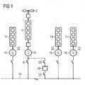
- this drive system In a simple drive system for watercraft, this drive system according to Fig. 1 only a propeller 2 or propeller 2, which is a diesel engine 4, also referred to as the main diesel engine driven.
- This diesel engine 4 drives not only the propeller 2, but also a generator 6, the load side by means of a contactor 8 with a vehicle electrical system 10 is connected.
- this drive system has at least one auxiliary generator unit 12.
- three auxiliary generator units 12 are shown, each consisting of a diesel engine 14 and a power generator 16.
- the diesel engine 14 of each auxiliary generator assembly 12 is also referred to as an auxiliary diesel engine.
- the power generators 16 are each connected on the load side to the vehicle electrical system 10 of the watercraft.
- this drive system additionally has an inverter 18, which, on the one hand, serves to start the generator 6 and, on the other hand, if the main diesel fails to operate the generator 6 as a motor becomes. For this reason, this inverter 18 generator and onboard each side a contactor 20 and 22.
- this operating state is referred to as Power Take In (PTI).
- PTI Power Take In
- PTO power take-off
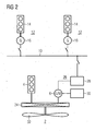
- FIG. 2 Another propulsion system for watercraft is known and for further explanation in the FIG. 2 shown schematically.
- This known drive system has a diesel engine 4, a transmission 24, a propeller 2, at least one diesel generator unit 12 and a machine system 26.
- the diesel engine 4 is connected by means of the gearbox 24 to the propeller 2 of the watercraft.
- the machine system 26 is connected by means of the gear 24 with the propeller 2.
- the machine system 26 includes a generator 6, referred to in this publication as a wave generator, a power link converter 28 and an excitation device 30.
- the wave generator 6 is the stator side electrically connectable by means of the current intermediate-circuit converter 28 to the electrical system 10.
- the exciter device 30, which has, for example, an exciter converter with matching transformer, is electrically conductively connected to the field winding of the wave generator 6.
- the rotor of this wave generator 6 is connected to the transmission 24.
- a wave generator 6 a third-excited synchronous machine is provided, which is operated predominantly as a generator.
- the power intermediate converter 28 which has a rectifier on the generator side and an inverter on the power supply side, decouples the vehicle electrical system 10 from the wave generator 6 in frequency.
- the rectifier and the inverter of the intermediate current converter 28 are connected to one another on the DC side by means of a DC intermediate circuit.
- This DC intermediate circuit is formed by means of a choke, which is required in order to limit converter currents in the event of a fault and short circuit.
- This DC intermediate-circuit converter 28 is provided on the power supply side with a mains choke for short-circuit current and harmonics limitation.
- the outlined machine model 26 is referred to as a wave generator system.
- the wave generator of this wave generator system which is driven by the transmission 24 from the main diesel 4, cheap electrical energy is generated on a watercraft.
- this DC link converter 28 can also supply power in the reverse direction, i. transferred from the electrical system 10 to the wave generator 6.
- the wave generator 6 operates as a motor and may be e.g. be used as a ship emergency drive. In this operation, the main diesel 4 is turned off.
- the energy for operating the wave generator 6 as an engine supply diesel generator sets 12, each having a diesel engine 14 and a power generator 16.
- the main diesel 4 can be operated economically, it is operated at a constant, for example rated speed. So that the speed of the vessel can be controlled, the propeller has 2 propeller blades 32, which are adjustable in their pitch.
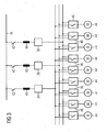
- a drive unit for loading and unloading pumps is shown.
- the pumps are not explicitly shown.
- three inverters 34, 36 and 38 belong to this drive unit, to which in each case one throttle 40 is connected on the power supply side.
- These Throttles 40 are each electrically connectable by means of a contactor 42 to the electrical system 10 of the watercraft.
- a three-phase voltage network of variable voltage and variable frequency is available at each converter 34, 36 and 38.
- Each motor 44 of a pump of a loading and Entladepumpenan extract can be connected by means of a switch means 46 with one of these three generated three-phase networks.
- each three-phase voltage network can be set to a predetermined variable voltage and frequency independently of the other two three-phase networks. This is advantageous if the existing loading and unloading pumps have different operating voltages and speeds.
- Such a drive unit is only used when the vessel is anchored at the quay of a port and is deleted or loaded. Since the residence times of a watercraft in the port are negligible compared to the dwell times at sea, the economic efficiency of this drive unit relative to the watercraft is low from the perspective of a shipowner.
- the invention is based on the object, the known drive system for a watercraft in such a way that this is easier.
- the previous converter is saved for the generator driven by the main diesel engine. Since this inverter is only used when the watercraft is not deleted or loaded, the function of this inverter can also be taken over by at least one of the drive unit of the drive unit. This saving of the converter for starting up the generator or for operating the generator as a motor in the PTI operating state saves space and weight.
- a drive system which is also referred to as a wave generator system, not only the inverter of this wave generator system, but also the starting transformer is saved.
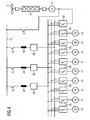
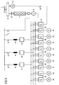
- the Fig. 4 shows a first embodiment of a propulsion system for a watercraft according to the invention.
- This drive system according to the invention is characterized in that that the generator 6 of the Fig. 1 by means of an additional switch device 48 with at least one of the three three-phase voltage networks, each of which is present at a converter 34, 36 and 38 of the drive unit for at least one implement, is connectable.
- This switch device 48 is constructed in the same way as the switch devices 46 of the known drive unit for the loading and unloading pumps. That is, by means of this switch means 48, one, two or three generated three-phase networks can be connected in parallel. How many of these three inverters 34, 36 and 38 and thus the generated three-phase voltage networks must be connected in parallel depends on the energy required to start the generator 6.
- the contactor 8 is closed, whereby the generator 6 functions as a motor (PTI).
- the switch device 48 is opened again, as in undisturbed case, the converter or the 34, 36 and 38 are no longer required for driving.
- the embodiment of the drive system according to Fig. 5 is created by an interconnection of the drive unit according to the invention Fig. 3 with the drive unit after Fig. 2 , This interconnection according to the invention, the power source inverter 28 of the Fig. 2 saved.
- the generator 6 by means of at least one inverter 34, 36 or 38 with the electrical system 10 is electrically conductively connected.
- the number of inverters 34, 36 or 38 to be used for the drive unit for the loading and unloading pumps depends on the electrical power generated by the generator 6.
- the generator 6 can be connected on-board to one of the three converters 34, 36 or 38, with two inverters 34, 36 or 36, 38 or 38, 34 connected in parallel or be connected to three parallel converters 34, 36 and 38.
- the inverter 34, 36 and 38 are now controlled so then energy from the electrical system 10 to the generator. 6 can get.
- the generator 6 is operated by a motor, so that an emergency operation can be maintained.
- a third embodiment of the drive system according to the invention is shown in more detail. This differs from the embodiment according to Fig. 4 in that in addition a booster motor 52 is provided.
- This additional booster motor 52 is connected by means of the gear 24 with the propeller 2 of the watercraft.
- a drive unit for the propeller 2 is a so-called hybrid drive.
- the energy for the booster motor 52 is provided from the electrical system 10.
- this bordnetz wherby-stunaser 10 is electrically connected directly to the electrical system 10.
- the booster motor 52 is connected by means of the switch device 48 with a predetermined number of converters 34, 36 or 38 of the drive unit for loading and unloading. With the help of the converter or the converter 34, 36, 38 of this drive unit, the power supplied to the booster motor 52 can be controlled.
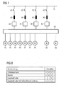
- FIG. 7 is a universal drive unit of a drive system according to the invention shown.
- all of the switch devices 46 and additional switch devices 48 are as shown in FIG Fig. 4 or 5 or 6 in a matrix device 58 summarized.
- a plurality of electric motors 44, 52 and 60 are connected.
- the electric motors of the loading and unloading pumps are the FIGS. 4 . 5 or 6
- the booster engine is the Fig. 6 and 60 denotes the electric motor of a bow thruster.
- four inverters 34, 36, 38 and 62 are connected on the output side to the connections of the matrix device 58 in this illustration. According to the Fig. 4 .
- each inverter 34, 36, 38, 62 on-board electrical side by means of a throttle 40 and a contactor 42 with the electrical system 10 of the watercraft electrically conductive connected.
- This drive unit can also differ from the Fig. 4 . 5 . 6 or have this representation only two or more than four inverters 34, 36, 38 and 62.
- a table is shown from which it can be seen how many of these four inverters 34, 36, 38 and 62 are needed for the individual drive tasks. For example, two inverters, namely the inverters 38 and 62, are needed to drive the motor 60 of the bow thruster. How many of the installed propulsion unit drives for a vessel must be used for individual propulsion tasks depends primarily on the total power required and the power of the drives.
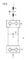
- FIG. 9 is a block diagram of a regenerative voltage source inverter 34 and 36 or 38 and 62 shown in more detail.
- These regenerative voltage source inverter 34, 36, 38, 62 are so linked to the matrix device 58 and the electrical system 10, that in each case its network-side converter 64 are connected by means of a contactor 42 to the electrical system 10 and that in each case its load-side converter 66 with inputs of Matrix device 58 are connected.
- the line-side converter 64 and the load-side converter 66 are electrically conductively connected to each other on the DC side by means of a DC intermediate circuit 68, formed from at least one electrolytic capacitor 70.
- the network-side converter 64 On the AC side, the network-side converter 64 has a line filter 72, which has a filter capacitor 74 and two filter chokes 40 and 76.
- the network-side power converter 64 with the input-side throttle 40 is in The power converter technology also known as Active Front End (AFE).
- AFE Active Front End
- Insulated gate bipolar transistors, so-called IGBTs, are provided as converter valves of the network-side converter 64 and of the load-side converter 66 in accordance with this block diagram of the regenerative voltage source converter 34 or 36 or 38 or 62.
- any other turn-off semiconductor switch can be used in each case as a converter valve of these two power converters 64 and 66.
- a self-commutated, pulsed IGBT regenerative input / output converter in conjunction with the filter has negligible network feedback and enables reactive power compensation.
- a converter with this block diagram is commercially available as a converter control cabinet ( Siemens catalog D21.3, May 2004, entitled “SINAMICS S150 inverter cabinets 75kW to 1200kW ”) available.
- this inventive drive system for a watercraft consisting of a drive unit for the propeller 2 and a drive unit for implements, these two drive units are linked together.
- the drive unit is used for the implements for other drive tasks.
- at least one converter unit is saved in the drive unit for the propeller 2. This saving reduces the space required and the weight of the drive system according to the invention.
- the installed drive power is used over a much longer period of operation, so that the economic efficiency of this drive system increases significantly.
Landscapes
- Engineering & Computer Science (AREA)
- Chemical & Material Sciences (AREA)
- Combustion & Propulsion (AREA)
- Mechanical Engineering (AREA)
- Ocean & Marine Engineering (AREA)
- Power Engineering (AREA)
- Aviation & Aerospace Engineering (AREA)
- Control Of Eletrric Generators (AREA)
- Electric Propulsion And Braking For Vehicles (AREA)
Claims (8)
- Système de propulsion d'un bâtiment de navigation ayant un moteur (4) diesel, une hélice (2), au moins un groupe ( 12 ) de génératrice auxiliaire, une génératrice ( 6 ) et un groupe d'entraînement d'au moins un appareil fournissant du travail, le moteur (4) diesel pouvant être relié, d'une part, à l'hélice (2) et, d'autre part, à l'aide de la génératrice ( 6 ), à un réseau ( 10 ) de bord du bâtiment de navigation et le groupe d'entraînement des appareils fournissant du travail ayant au moins un convertisseur ( 34, 36, 38, 62 ), qui, d'une part, peut être relié au réseau ( 10 ) de bord et, d'autre part, aux appareils fournissant du travail, caractérisé en ce qu'au moins l'un de ces convertisseurs ( 34, 36, 38, 62 ) du groupe d'entraînement d'appareils fournissant du travail est relié du côté de la charge à la génératrice ( 6 ) au moyen d'un dispositif ( 48 ) de commutation.
- Système de propulsion suivant la revendication 1, caractérisé en ce que la génératrice ( 6 ) et le moteur ( 4 ) diesel sont combinés à l'hélice ( 2 ) au moyen d'une transmission ( 24 ).
- Système de propulsion suivant l'une des revendications précédentes, caractérisé en ce que les appareils fournissant du travail et la génératrice ( 6 ) peuvent, au moyen d'un dispositif ( 58 ) matriciel, être reliés aux bornes du côté de la charge du convertisseur ( 34, 36, 38, 62 ) du groupe d'entraînement des appareils fournissant du travail.
- Système de propulsion suivant l'une des revendications précédentes, caractérisé en ce que chaque convertisseur ( 34, 36, 38, 62 ) du groupe d'entraînement des appareils fournissant du travail est un convertisseur de circuit intermédiaire de tension.
- Système de propulsion suivant la revendication 4, caractérisé en ce que le convertisseur de circuit intermédiaire de tension est constitué de manière à pouvoir être alimenté en retour.
- Système de propulsion suivant l'une des revendications précédentes, caractérisé en ce que le groupe ( 12 ) de génératrice auxiliaire a un moteur ( 14 ) diesel et une génératrice ( 16 ) de courant.
- Système de propulsion suivant l'une des revendications précédentes, caractérisé en ce que l'appareil fournissant du travail est une pompe.
- Système de propulsion suivant l'une des revendications 1 à 6, caractérisé en ce que l'appareil fournissant du travail est un gouvernail transversal d'étrave.
Applications Claiming Priority (2)
| Application Number | Priority Date | Filing Date | Title |
|---|---|---|---|
| DE102005059761A DE102005059761B4 (de) | 2005-12-14 | 2005-12-14 | Antriebssystem für ein Wasserfahrzeug |
| PCT/EP2006/067259 WO2007068514A1 (fr) | 2005-12-14 | 2006-10-11 | Systeme d'entrainement hybride pour navire |
Publications (2)
| Publication Number | Publication Date |
|---|---|
| EP1960260A1 EP1960260A1 (fr) | 2008-08-27 |
| EP1960260B1 true EP1960260B1 (fr) | 2015-07-29 |
Family
ID=37668125
Family Applications (1)
| Application Number | Title | Priority Date | Filing Date |
|---|---|---|---|
| EP06807136.4A Not-in-force EP1960260B1 (fr) | 2005-12-14 | 2006-10-11 | Systeme d'entrainement hybride pour navire |
Country Status (8)
| Country | Link |
|---|---|
| US (1) | US20080315583A1 (fr) |
| EP (1) | EP1960260B1 (fr) |
| KR (1) | KR101258141B1 (fr) |
| CN (1) | CN101326098B (fr) |
| DE (1) | DE102005059761B4 (fr) |
| DK (1) | DK1960260T3 (fr) |
| ES (1) | ES2550142T3 (fr) |
| WO (1) | WO2007068514A1 (fr) |
Cited By (1)
| Publication number | Priority date | Publication date | Assignee | Title |
|---|---|---|---|---|
| CN107444601A (zh) * | 2017-08-15 | 2017-12-08 | 上海船舶研究设计院(中国船舶工业集团公司第六0四研究院) | 一种柴电混合推进系统及静态进入pti的方法 |
Families Citing this family (32)
| Publication number | Priority date | Publication date | Assignee | Title |
|---|---|---|---|---|
| US8244419B2 (en) * | 2006-10-24 | 2012-08-14 | Mi-Jack Canada, Inc. | Marine power train system and method of storing energy in a marine vehicle |
| US8706330B2 (en) * | 2008-11-14 | 2014-04-22 | Hybrid Innovation Technologies Llc | Electronic system and method of automating, controlling, and optimizing the operation of one or more energy storage units and a combined serial and parallel hybrid marine propulsion system |
| US8393926B2 (en) * | 2009-02-12 | 2013-03-12 | Twin Disc, Inc. | Hybrid marine power train system |
| JP4980391B2 (ja) * | 2009-03-31 | 2012-07-18 | 三井造船株式会社 | 舶用動力システム |
| FR2949750B1 (fr) * | 2009-09-04 | 2011-10-07 | Converteam Technology Ltd | Chaine de propulsion |
| DE102009043530A1 (de) * | 2009-09-30 | 2011-04-07 | Siemens Aktiengesellschaft | Elektrische Antriebswelle und Fahrzeug mit einer derartigen elektrischen Antriebswelle |
| NO332138B2 (no) | 2009-11-09 | 2016-04-11 | Rolls Royce Marine As Power Electric Systems Bergen | Hybrid fremdriftssystem for et fartøy |
| EP2627557B1 (fr) * | 2010-10-14 | 2023-01-25 | GE Energy Power Conversion Technology Ltd | Systèmes de propulsion marins |
| CN102120488A (zh) * | 2011-03-07 | 2011-07-13 | 上海海事大学 | 混合动力船舶电力推进系统及实施方法 |
| CN102130455B (zh) * | 2011-03-15 | 2013-08-28 | 荣信电力电子股份有限公司 | 港口岸基变频供电系统 |
| JP5830309B2 (ja) * | 2011-09-01 | 2015-12-09 | 日本郵船株式会社 | 船舶の推進装置 |
| DE102012100175A1 (de) * | 2012-01-10 | 2013-07-11 | MSG eG | Binnenschiff und Verfahren zum Betrieb eines Binnenschiffs |
| KR101637335B1 (ko) * | 2012-07-10 | 2016-07-07 | 대우조선해양 주식회사 | 부유식 구조물의 전력 관리 시스템 및 그의 전력 관리 방법 |
| US9346363B2 (en) * | 2012-08-13 | 2016-05-24 | Mitsubishi Electric Corporation | Propulsion control apparatus of engine hybrid railroad vehicle |
| CN103085960B (zh) * | 2013-01-24 | 2016-04-20 | 上海航盛船舶设计有限公司 | 一种柴电混合推进的金枪鱼延绳钓船 |
| GB2514183B (en) | 2013-05-17 | 2015-09-09 | Perkins Engines Co Ltd | A propulsion system incorporating a plurality of energy conversion machines |
| JP6175281B2 (ja) * | 2013-05-24 | 2017-08-02 | 西芝電機株式会社 | 船舶推進加勢システム |
| JP6187930B2 (ja) * | 2013-06-21 | 2017-08-30 | 国立研究開発法人 海上・港湾・航空技術研究所 | ハイブリッド推進システム及びそれを搭載したハイブリッド推進船 |
| DE102013021838A1 (de) * | 2013-12-21 | 2015-06-25 | Peter Andersen | Verfahren zur Inbetriebsetzung einer Brennkraftmaschine eines Generatorsatzes eines elektrischen Energieverteilungssystems an Bord eines Schiffes |
| CN103921925A (zh) * | 2014-04-07 | 2014-07-16 | 深圳市云洲创新科技有限公司 | 油电混合动力推动和管理系统及无人船 |
| NL2012743B1 (en) * | 2014-05-02 | 2016-02-23 | Ihc Holland Ie Bv | Power unit and drive system. |
| NO2990327T3 (fr) | 2014-08-29 | 2018-09-22 | ||
| CN104210637B (zh) * | 2014-09-26 | 2016-10-19 | 永济新时速电机电器有限责任公司 | 一种电力推进船舶变流器控制单元 |
| JP6697218B2 (ja) * | 2014-11-11 | 2020-05-20 | 川崎重工業株式会社 | 船舶の推進システム |
| KR101707513B1 (ko) * | 2015-01-21 | 2017-02-16 | 대우조선해양 주식회사 | 이중연료로 추진되는 시추선 |
| KR101707512B1 (ko) * | 2015-01-21 | 2017-02-16 | 대우조선해양 주식회사 | 이중연료로 추진되는 시추선 |
| JP2016137821A (ja) * | 2015-01-28 | 2016-08-04 | ヤマハ発動機株式会社 | 船舶推進装置および船舶 |
| CN105015752B (zh) * | 2015-08-06 | 2017-08-15 | 江苏磁谷科技股份有限公司 | 磁耦合推进系统及其在船舶推进上的应用 |
| DE102016117327A1 (de) * | 2016-09-15 | 2018-03-15 | Knorr-Bremse Systeme für Schienenfahrzeuge GmbH | Hilfsaggregat für eine Lokomotive |
| CN107140169B (zh) * | 2017-05-24 | 2019-06-21 | 大鹏高科(武汉)智能装备有限公司 | 一种模块化的无人船智能动力控制系统 |
| KR102512512B1 (ko) * | 2020-09-03 | 2023-03-22 | 한국과학기술연구원 | 은 원소가 혼입된 찰코파이라이트 화합물계 박막 및 그 제조 방법 |
| GB202113071D0 (en) * | 2021-09-14 | 2021-10-27 | Siemens Energy AS | Hybrid combined cycle power system |
Family Cites Families (44)
| Publication number | Priority date | Publication date | Assignee | Title |
|---|---|---|---|---|
| US2114859A (en) * | 1938-04-19 | Synchro-tie for ship propulsion | ||
| US1206254A (en) * | 1912-08-23 | 1916-11-28 | Martin Roellig | Subsidiary plant for driving propeller-shafts when not under load. |
| US1861750A (en) * | 1928-12-10 | 1932-06-07 | Bbc Brown Boveri & Cie | Method of regulation of ship-propulsion systems |
| DE1682150U (de) * | 1950-10-30 | 1954-08-26 | Siemens Ag | Elektrische energieerzeugungsanlage fuer mit impulserzeugungseinrichtungen fuer die elektrofischerei ausgeruestete, elektrisch angetriebene schiffe. |
| DD54909A1 (de) * | 1966-03-07 | 1967-03-20 | Klaus Goetzen | Anordnung zum Parallelbetrieb von Drehstrom Generatoren mit einer Drehstrom Wellenmaschine auf Schiffen mit Verstellpropeller |
| US3515088A (en) * | 1967-10-31 | 1970-06-02 | Goetaverken Ab | Bow thruster |
| US3517633A (en) * | 1968-09-10 | 1970-06-30 | Mathewson Corp | Bow thruster |
| DE2206513B2 (de) * | 1972-02-08 | 1973-12-20 | Mannesmann-Meer Ag, 4050 Moenchengladbach | Kombinierte Antriebsanlage für Schiffe mit Motoren beliebiger Art und einer Gasturbine mit Schaltkupplung |
| US3818307A (en) * | 1972-07-31 | 1974-06-18 | Bell Telephone Labor Inc | Serially-connected converters having multiple regulation modes for use in supplying serially-connected loads on long lines |
| FR2351277A1 (fr) * | 1976-05-11 | 1977-12-09 | Spie Batignolles | Systeme pour transformer l'energie aleatoire d'un fluide naturel |
| DE2758555C2 (de) * | 1977-12-23 | 1980-01-03 | Mannesmann Ag, 4000 Duesseldorf | Zweistufiges Schaltgetriebe für den Antrieb eines Generators von einer Schiffsantriebsanlage |
| DE2927386B1 (de) * | 1979-07-04 | 1981-01-29 | Mannesmann Ag | Schiffsgetriebe mit einer Nebenabtriebswelle |
| JPS592114A (ja) * | 1982-06-29 | 1984-01-07 | Nishishiba Denki Kk | 船舶用電源装置 |
| EP0117881B1 (fr) * | 1983-03-03 | 1986-06-18 | Licentia Patent-Verwaltungs-GmbH | Installation de propulsion marine à hélices principale et supplémentaire |
| JPS59166000A (ja) * | 1983-03-10 | 1984-09-19 | Nishishiba Denki Kk | 船舶用電源装置の運転方法 |
| DE3536448A1 (de) * | 1984-06-27 | 1987-04-16 | Licentia Gmbh | Stromversorgungsanlage mit einem wellengenerator |
| US4661714A (en) * | 1985-06-17 | 1987-04-28 | Satterthwaite J Glenn | Electric marine propulsion system |
| FI890004A7 (fi) * | 1988-08-03 | 1990-02-04 | Siemens Ag | Foerfarande foer att undvika vaexelriktarlaosning vid en till naetet aotermatande stroemriktare av en naetsidig reverseringsstroemriktare av en spaenningsmellankrets-omriktare vid dynamisk spaenningssaenkning och kopplingsanordning foer genomfoerande av foerfarandet. |
| JPH07132885A (ja) * | 1993-11-09 | 1995-05-23 | Mitsubishi Heavy Ind Ltd | ディーゼル/電気推進併用の油タンカー推進システム |
| DE4432483A1 (de) * | 1994-09-13 | 1996-03-14 | Blohm Voss Ag | Zusatzantrieb für Seeschiffe |
| DE19723611A1 (de) * | 1997-06-05 | 1998-12-10 | Blohm Voss Ag | Antriebsanlage für Schiffe, vorzugsweise für Marineschiffe |
| CN2355494Y (zh) * | 1997-11-12 | 1999-12-22 | 湛江海洋大学工程学院 | 电液控制式船舶主机轴带同步发电机装置 |
| US6234100B1 (en) * | 1998-09-03 | 2001-05-22 | The Talaria Company, Llc | Stick control system for waterjet boats |
| US6009822A (en) * | 1999-03-29 | 2000-01-04 | Aron; Douglas A. | Bow or stern thruster |
| JP3990155B2 (ja) * | 2000-01-14 | 2007-10-10 | シーメンス アクチエンゲゼルシヤフト | 船舶推進駆動システム |
| WO2001076938A2 (fr) * | 2000-04-07 | 2001-10-18 | The Talaria Company, Llc | Systeme de commande de godet differentiel pour bateaux a propulsion par hydrojet |
| DE10061578A1 (de) * | 2000-12-11 | 2002-06-27 | Siemens Ag | Hybridantrieb für Schiffe |
| JP3707680B2 (ja) * | 2002-01-25 | 2005-10-19 | 松下電器産業株式会社 | 駆動電圧制御装置 |
| US20030178960A1 (en) * | 2002-03-21 | 2003-09-25 | Kassing David M. | Apparatus and method for controlling self-contained power generation and power utilization system |
| EP1661747A4 (fr) * | 2003-08-12 | 2011-07-27 | Nissan Diesel Motor Co | Systeme d'entrainement hybride pour vehicule |
| NO20033876A (no) * | 2003-09-02 | 2005-02-21 | Norpropeller As | Drivsystem for skip |
| DE10353967A1 (de) * | 2003-11-19 | 2005-07-07 | Siemens Ag | Energieerzeugungs-, Verteilungs- und Bordstromversorgungssystem für emissionsarme Überwasser-Marine(Navy)-Schiffe unterschiedlicher Klassen und Größen |
| US7150240B2 (en) * | 2004-03-17 | 2006-12-19 | Delphi Technologies, Inc. | Method and apparatus for maneuvering a watercraft |
| DE102004048754A1 (de) * | 2004-10-05 | 2006-04-13 | Voith Turbo Gmbh & Co. Kg | Pod-Schiffsantrieb mit Getriebe |
| KR100593926B1 (ko) * | 2004-10-07 | 2006-06-30 | 삼성전기주식회사 | 동기 정류기를 갖는 플라이백 컨버터 |
| US7321500B2 (en) * | 2005-04-29 | 2008-01-22 | Abb Technology Ltd. | Electric power converter |
| EP1945946A1 (fr) * | 2005-10-31 | 2008-07-23 | Chapdrive As | Systeme de production d'energie electrique a turbine et procede de commande dudit systeme |
| US7576443B2 (en) * | 2006-12-15 | 2009-08-18 | General Electric Company | Method and apparatus for generating electric power |
| GB0705248D0 (en) * | 2007-03-19 | 2007-04-25 | Cummins Generator Technologies | Propulsion arrangement |
| AU2008257541C1 (en) * | 2007-06-01 | 2014-08-28 | Siemens Aktiengesellschaft | Method and apparatus for operation of a marine vessel hybrid propulsion system |
| EP2225118B1 (fr) * | 2007-12-12 | 2016-06-22 | Foss Maritime Company | Systèmes hybrides de propulsion |
| JP5481059B2 (ja) * | 2008-11-28 | 2014-04-23 | ヤマハ発動機株式会社 | 操船支援装置およびそれを備えた船舶 |
| JP5371401B2 (ja) * | 2008-12-04 | 2013-12-18 | ヤマハ発動機株式会社 | 操船支援装置およびそれを備えた船舶 |
| JP5367382B2 (ja) * | 2009-01-07 | 2013-12-11 | ヤマハ発動機株式会社 | 船舶の電源システム |
-
2005
- 2005-12-14 DE DE102005059761A patent/DE102005059761B4/de not_active Expired - Fee Related
-
2006
- 2006-10-11 EP EP06807136.4A patent/EP1960260B1/fr not_active Not-in-force
- 2006-10-11 ES ES06807136.4T patent/ES2550142T3/es active Active
- 2006-10-11 US US12/097,335 patent/US20080315583A1/en not_active Abandoned
- 2006-10-11 CN CN2006800467262A patent/CN101326098B/zh not_active Expired - Fee Related
- 2006-10-11 WO PCT/EP2006/067259 patent/WO2007068514A1/fr not_active Ceased
- 2006-10-11 DK DK06807136.4T patent/DK1960260T3/en active
- 2006-10-11 KR KR1020087017042A patent/KR101258141B1/ko not_active Expired - Fee Related
Cited By (1)
| Publication number | Priority date | Publication date | Assignee | Title |
|---|---|---|---|---|
| CN107444601A (zh) * | 2017-08-15 | 2017-12-08 | 上海船舶研究设计院(中国船舶工业集团公司第六0四研究院) | 一种柴电混合推进系统及静态进入pti的方法 |
Also Published As
| Publication number | Publication date |
|---|---|
| DE102005059761A1 (de) | 2007-06-28 |
| KR20080077014A (ko) | 2008-08-20 |
| ES2550142T3 (es) | 2015-11-04 |
| WO2007068514A1 (fr) | 2007-06-21 |
| US20080315583A1 (en) | 2008-12-25 |
| DE102005059761B4 (de) | 2007-12-06 |
| CN101326098B (zh) | 2012-04-25 |
| DK1960260T3 (en) | 2015-10-26 |
| KR101258141B1 (ko) | 2013-04-25 |
| EP1960260A1 (fr) | 2008-08-27 |
| CN101326098A (zh) | 2008-12-17 |
Similar Documents
| Publication | Publication Date | Title |
|---|---|---|
| EP1960260B1 (fr) | Systeme d'entrainement hybride pour navire | |
| EP2580857B1 (fr) | Système de génératrice de ligne d'arbre | |
| EP1992063B1 (fr) | Système d'entraînement diesel/électrique comprenant un générateur synchrone à excitation permanente | |
| EP2483146B1 (fr) | Arbre d'entraînement électrique et véhicule doté d'un tel arbre d'entraînement électrique | |
| DE102006020144B4 (de) | Verfahren zum Betrieb eines Schiffsantriebssystems mit Abwärmerückgewinnung sowie Schiffsantriebssystem mit Abwärmerückgewinnung | |
| EP2090508B1 (fr) | Système d'alimentation en énergie électrique, notamment pour bateaux | |
| EP3853960B1 (fr) | Système de distribution électrique pour une installation hydraulique | |
| DE102008023332B4 (de) | Dieselelektrisches Antriebssystem | |
| EP1894836B1 (fr) | Navire doté d'un entraînement électrique et entraînement auxiliaire de moteurs à combustion interne | |
| DE102010009951B4 (de) | Verfahren zum Antrieb eines Fahrzeugs | |
| EP2570290B1 (fr) | Système d'entraînement d'un véhicule fonctionnant sur batterie doté d'une machine synchrone à excitation permanente alimentée par convertisseur | |
| EP0122445B1 (fr) | Alimentation continue par le réseau de bord à partir du réseau de navigation dans la propulsion de navire à courant alternatif à fréquence variable et convertisseur partiel de fréquence | |
| DE102005059760B4 (de) | Antriebssystem für ein Wasserfahrzeug | |
| EP0982828A2 (fr) | Méthode et dispositif de compensation de la puissance réactive dans des réseaux embarqués | |
| EP2949572B1 (fr) | Système de propulsion pour un bateau et son fonctionnement | |
| DE3212457C2 (de) | Wellengeneratoranlage mit Synchron-Phasenschieber, insbesondere für Schiffe | |
| DE2237400A1 (de) | Antriebs- und stromversorgungsanlage fuer schiffe | |
| DE3212430A1 (de) | Wellengeneratoranlage mit gleichstromzwischenkreis, insbesondere fuer schiffe | |
| DE102024115717A1 (de) | Antriebsstrang eines Kraftfahrzeugs | |
| DE102023103117A1 (de) | E-Maschine mit Wicklungsumschaltung und Verfahren zum Regeln des Betriebs einer solchen E-Maschine | |
| WO2015180930A1 (fr) | Système de propulsion pour navire et son fonctionnement | |
| EP3940912A1 (fr) | Système d'alimentation électrique | |
| DE102018217722A1 (de) | Elektrische Maschine und Kraftwagen mit einer elektrischen Maschine |
Legal Events
| Date | Code | Title | Description |
|---|---|---|---|
| PUAI | Public reference made under article 153(3) epc to a published international application that has entered the european phase |
Free format text: ORIGINAL CODE: 0009012 |
|
| 17P | Request for examination filed |
Effective date: 20080612 |
|
| AK | Designated contracting states |
Kind code of ref document: A1 Designated state(s): AT BE BG CH CY CZ DE DK EE ES FI FR GB GR HU IE IS IT LI LT LU LV MC NL PL PT RO SE SI SK TR |
|
| RIN1 | Information on inventor provided before grant (corrected) |
Inventor name: VAN MOL, WIL Inventor name: BECK, OLIVER |
|
| RIN1 | Information on inventor provided before grant (corrected) |
Inventor name: VAN MOL, WIL Inventor name: BECK, OLIVER |
|
| 17Q | First examination report despatched |
Effective date: 20110311 |
|
| DAX | Request for extension of the european patent (deleted) | ||
| RAP1 | Party data changed (applicant data changed or rights of an application transferred) |
Owner name: SIEMENS AKTIENGESELLSCHAFT |
|
| GRAP | Despatch of communication of intention to grant a patent |
Free format text: ORIGINAL CODE: EPIDOSNIGR1 |
|
| INTG | Intention to grant announced |
Effective date: 20150224 |
|
| GRAS | Grant fee paid |
Free format text: ORIGINAL CODE: EPIDOSNIGR3 |
|
| GRAA | (expected) grant |
Free format text: ORIGINAL CODE: 0009210 |
|
| AK | Designated contracting states |
Kind code of ref document: B1 Designated state(s): AT BE BG CH CY CZ DE DK EE ES FI FR GB GR HU IE IS IT LI LT LU LV MC NL PL PT RO SE SI SK TR |
|
| REG | Reference to a national code |
Ref country code: GB Ref legal event code: FG4D Free format text: NOT ENGLISH |
|
| REG | Reference to a national code |
Ref country code: CH Ref legal event code: EP |
|
| REG | Reference to a national code |
Ref country code: AT Ref legal event code: REF Ref document number: 739038 Country of ref document: AT Kind code of ref document: T Effective date: 20150815 |
|
| REG | Reference to a national code |
Ref country code: IE Ref legal event code: FG4D Free format text: LANGUAGE OF EP DOCUMENT: GERMAN |
|
| REG | Reference to a national code |
Ref country code: DE Ref legal event code: R096 Ref document number: 502006014450 Country of ref document: DE |
|
| REG | Reference to a national code |
Ref country code: FR Ref legal event code: PLFP Year of fee payment: 10 |
|
| REG | Reference to a national code |
Ref country code: DK Ref legal event code: T3 Effective date: 20151020 |
|
| REG | Reference to a national code |
Ref country code: ES Ref legal event code: FG2A Ref document number: 2550142 Country of ref document: ES Kind code of ref document: T3 Effective date: 20151104 |
|
| REG | Reference to a national code |
Ref country code: NL Ref legal event code: FP |
|
| REG | Reference to a national code |
Ref country code: LT Ref legal event code: MG4D |
|
| PGFP | Annual fee paid to national office [announced via postgrant information from national office to epo] |
Ref country code: DK Payment date: 20151021 Year of fee payment: 10 |
|
| PG25 | Lapsed in a contracting state [announced via postgrant information from national office to epo] |
Ref country code: LV Free format text: LAPSE BECAUSE OF FAILURE TO SUBMIT A TRANSLATION OF THE DESCRIPTION OR TO PAY THE FEE WITHIN THE PRESCRIBED TIME-LIMIT Effective date: 20150729 Ref country code: GR Free format text: LAPSE BECAUSE OF FAILURE TO SUBMIT A TRANSLATION OF THE DESCRIPTION OR TO PAY THE FEE WITHIN THE PRESCRIBED TIME-LIMIT Effective date: 20151030 Ref country code: LT Free format text: LAPSE BECAUSE OF FAILURE TO SUBMIT A TRANSLATION OF THE DESCRIPTION OR TO PAY THE FEE WITHIN THE PRESCRIBED TIME-LIMIT Effective date: 20150729 |
|
| PGFP | Annual fee paid to national office [announced via postgrant information from national office to epo] |
Ref country code: FI Payment date: 20151013 Year of fee payment: 10 |
|
| PG25 | Lapsed in a contracting state [announced via postgrant information from national office to epo] |
Ref country code: PT Free format text: LAPSE BECAUSE OF FAILURE TO SUBMIT A TRANSLATION OF THE DESCRIPTION OR TO PAY THE FEE WITHIN THE PRESCRIBED TIME-LIMIT Effective date: 20151130 Ref country code: IS Free format text: LAPSE BECAUSE OF FAILURE TO SUBMIT A TRANSLATION OF THE DESCRIPTION OR TO PAY THE FEE WITHIN THE PRESCRIBED TIME-LIMIT Effective date: 20151129 Ref country code: SE Free format text: LAPSE BECAUSE OF FAILURE TO SUBMIT A TRANSLATION OF THE DESCRIPTION OR TO PAY THE FEE WITHIN THE PRESCRIBED TIME-LIMIT Effective date: 20150729 Ref country code: PL Free format text: LAPSE BECAUSE OF FAILURE TO SUBMIT A TRANSLATION OF THE DESCRIPTION OR TO PAY THE FEE WITHIN THE PRESCRIBED TIME-LIMIT Effective date: 20150729 |
|
| PGFP | Annual fee paid to national office [announced via postgrant information from national office to epo] |
Ref country code: FR Payment date: 20151016 Year of fee payment: 10 Ref country code: NL Payment date: 20151021 Year of fee payment: 10 Ref country code: ES Payment date: 20151126 Year of fee payment: 10 |
|
| PG25 | Lapsed in a contracting state [announced via postgrant information from national office to epo] |
Ref country code: SK Free format text: LAPSE BECAUSE OF FAILURE TO SUBMIT A TRANSLATION OF THE DESCRIPTION OR TO PAY THE FEE WITHIN THE PRESCRIBED TIME-LIMIT Effective date: 20150729 Ref country code: EE Free format text: LAPSE BECAUSE OF FAILURE TO SUBMIT A TRANSLATION OF THE DESCRIPTION OR TO PAY THE FEE WITHIN THE PRESCRIBED TIME-LIMIT Effective date: 20150729 Ref country code: CZ Free format text: LAPSE BECAUSE OF FAILURE TO SUBMIT A TRANSLATION OF THE DESCRIPTION OR TO PAY THE FEE WITHIN THE PRESCRIBED TIME-LIMIT Effective date: 20150729 |
|
| PGFP | Annual fee paid to national office [announced via postgrant information from national office to epo] |
Ref country code: DE Payment date: 20151218 Year of fee payment: 10 Ref country code: IT Payment date: 20151027 Year of fee payment: 10 |
|
| REG | Reference to a national code |
Ref country code: DE Ref legal event code: R097 Ref document number: 502006014450 Country of ref document: DE |
|
| PG25 | Lapsed in a contracting state [announced via postgrant information from national office to epo] |
Ref country code: LU Free format text: LAPSE BECAUSE OF FAILURE TO SUBMIT A TRANSLATION OF THE DESCRIPTION OR TO PAY THE FEE WITHIN THE PRESCRIBED TIME-LIMIT Effective date: 20151011 Ref country code: RO Free format text: LAPSE BECAUSE OF FAILURE TO SUBMIT A TRANSLATION OF THE DESCRIPTION OR TO PAY THE FEE WITHIN THE PRESCRIBED TIME-LIMIT Effective date: 20150729 |
|
| REG | Reference to a national code |
Ref country code: CH Ref legal event code: PL |
|
| PLBE | No opposition filed within time limit |
Free format text: ORIGINAL CODE: 0009261 |
|
| STAA | Information on the status of an ep patent application or granted ep patent |
Free format text: STATUS: NO OPPOSITION FILED WITHIN TIME LIMIT |
|
| GBPC | Gb: european patent ceased through non-payment of renewal fee |
Effective date: 20151029 |
|
| PG25 | Lapsed in a contracting state [announced via postgrant information from national office to epo] |
Ref country code: MC Free format text: LAPSE BECAUSE OF FAILURE TO SUBMIT A TRANSLATION OF THE DESCRIPTION OR TO PAY THE FEE WITHIN THE PRESCRIBED TIME-LIMIT Effective date: 20150729 |
|
| 26N | No opposition filed |
Effective date: 20160502 |
|
| REG | Reference to a national code |
Ref country code: IE Ref legal event code: MM4A |
|
| PG25 | Lapsed in a contracting state [announced via postgrant information from national office to epo] |
Ref country code: GB Free format text: LAPSE BECAUSE OF NON-PAYMENT OF DUE FEES Effective date: 20151029 Ref country code: CH Free format text: LAPSE BECAUSE OF NON-PAYMENT OF DUE FEES Effective date: 20151031 Ref country code: LI Free format text: LAPSE BECAUSE OF NON-PAYMENT OF DUE FEES Effective date: 20151031 |
|
| PG25 | Lapsed in a contracting state [announced via postgrant information from national office to epo] |
Ref country code: SI Free format text: LAPSE BECAUSE OF FAILURE TO SUBMIT A TRANSLATION OF THE DESCRIPTION OR TO PAY THE FEE WITHIN THE PRESCRIBED TIME-LIMIT Effective date: 20150729 |
|
| PG25 | Lapsed in a contracting state [announced via postgrant information from national office to epo] |
Ref country code: IE Free format text: LAPSE BECAUSE OF NON-PAYMENT OF DUE FEES Effective date: 20151011 |
|
| REG | Reference to a national code |
Ref country code: AT Ref legal event code: MM01 Ref document number: 739038 Country of ref document: AT Kind code of ref document: T Effective date: 20151011 |
|
| PG25 | Lapsed in a contracting state [announced via postgrant information from national office to epo] |
Ref country code: AT Free format text: LAPSE BECAUSE OF NON-PAYMENT OF DUE FEES Effective date: 20151011 |
|
| REG | Reference to a national code |
Ref country code: DE Ref legal event code: R119 Ref document number: 502006014450 Country of ref document: DE |
|
| REG | Reference to a national code |
Ref country code: DK Ref legal event code: EBP Effective date: 20161031 |
|
| PG25 | Lapsed in a contracting state [announced via postgrant information from national office to epo] |
Ref country code: BG Free format text: LAPSE BECAUSE OF FAILURE TO SUBMIT A TRANSLATION OF THE DESCRIPTION OR TO PAY THE FEE WITHIN THE PRESCRIBED TIME-LIMIT Effective date: 20150729 Ref country code: HU Free format text: LAPSE BECAUSE OF FAILURE TO SUBMIT A TRANSLATION OF THE DESCRIPTION OR TO PAY THE FEE WITHIN THE PRESCRIBED TIME-LIMIT; INVALID AB INITIO Effective date: 20061011 |
|
| REG | Reference to a national code |
Ref country code: NL Ref legal event code: MM Effective date: 20161101 |
|
| PG25 | Lapsed in a contracting state [announced via postgrant information from national office to epo] |
Ref country code: CY Free format text: LAPSE BECAUSE OF FAILURE TO SUBMIT A TRANSLATION OF THE DESCRIPTION OR TO PAY THE FEE WITHIN THE PRESCRIBED TIME-LIMIT Effective date: 20150729 |
|
| REG | Reference to a national code |
Ref country code: FR Ref legal event code: ST Effective date: 20170630 |
|
| PG25 | Lapsed in a contracting state [announced via postgrant information from national office to epo] |
Ref country code: DE Free format text: LAPSE BECAUSE OF NON-PAYMENT OF DUE FEES Effective date: 20170503 Ref country code: BE Free format text: LAPSE BECAUSE OF NON-PAYMENT OF DUE FEES Effective date: 20151031 Ref country code: FI Free format text: LAPSE BECAUSE OF NON-PAYMENT OF DUE FEES Effective date: 20161011 Ref country code: FR Free format text: LAPSE BECAUSE OF NON-PAYMENT OF DUE FEES Effective date: 20161102 |
|
| PG25 | Lapsed in a contracting state [announced via postgrant information from national office to epo] |
Ref country code: NL Free format text: LAPSE BECAUSE OF NON-PAYMENT OF DUE FEES Effective date: 20161101 Ref country code: TR Free format text: LAPSE BECAUSE OF FAILURE TO SUBMIT A TRANSLATION OF THE DESCRIPTION OR TO PAY THE FEE WITHIN THE PRESCRIBED TIME-LIMIT Effective date: 20150729 |
|
| PG25 | Lapsed in a contracting state [announced via postgrant information from national office to epo] |
Ref country code: IT Free format text: LAPSE BECAUSE OF NON-PAYMENT OF DUE FEES Effective date: 20161011 |
|
| PG25 | Lapsed in a contracting state [announced via postgrant information from national office to epo] |
Ref country code: DK Free format text: LAPSE BECAUSE OF NON-PAYMENT OF DUE FEES Effective date: 20161031 |
|
| PG25 | Lapsed in a contracting state [announced via postgrant information from national office to epo] |
Ref country code: ES Free format text: LAPSE BECAUSE OF NON-PAYMENT OF DUE FEES Effective date: 20161012 |
|
| REG | Reference to a national code |
Ref country code: ES Ref legal event code: FD2A Effective date: 20181128 |