EP1963013B1 - Procedes de fabrication de membranes revetues d'un catalyseur - Google Patents
Procedes de fabrication de membranes revetues d'un catalyseur Download PDFInfo
- Publication number
- EP1963013B1 EP1963013B1 EP06828302A EP06828302A EP1963013B1 EP 1963013 B1 EP1963013 B1 EP 1963013B1 EP 06828302 A EP06828302 A EP 06828302A EP 06828302 A EP06828302 A EP 06828302A EP 1963013 B1 EP1963013 B1 EP 1963013B1
- Authority
- EP
- European Patent Office
- Prior art keywords
- catalyst
- micro
- membrane
- nano
- porous membrane
- Prior art date
- Legal status (The legal status is an assumption and is not a legal conclusion. Google has not performed a legal analysis and makes no representation as to the accuracy of the status listed.)
- Ceased
Links
Images
Classifications
-
- B—PERFORMING OPERATIONS; TRANSPORTING
- B01—PHYSICAL OR CHEMICAL PROCESSES OR APPARATUS IN GENERAL
- B01J—CHEMICAL OR PHYSICAL PROCESSES, e.g. CATALYSIS OR COLLOID CHEMISTRY; THEIR RELEVANT APPARATUS
- B01J37/00—Processes, in general, for preparing catalysts; Processes, in general, for activation of catalysts
- B01J37/02—Impregnation, coating or precipitation
-
- B—PERFORMING OPERATIONS; TRANSPORTING
- B01—PHYSICAL OR CHEMICAL PROCESSES OR APPARATUS IN GENERAL
- B01D—SEPARATION
- B01D67/00—Processes specially adapted for manufacturing semi-permeable membranes for separation processes or apparatus
- B01D67/0079—Manufacture of membranes comprising organic and inorganic components
- B01D67/00791—Different components in separate layers
-
- B—PERFORMING OPERATIONS; TRANSPORTING
- B01—PHYSICAL OR CHEMICAL PROCESSES OR APPARATUS IN GENERAL
- B01D—SEPARATION
- B01D67/00—Processes specially adapted for manufacturing semi-permeable membranes for separation processes or apparatus
- B01D67/0079—Manufacture of membranes comprising organic and inorganic components
- B01D67/00793—Dispersing a component, e.g. as particles or powder, in another component
-
- B—PERFORMING OPERATIONS; TRANSPORTING
- B01—PHYSICAL OR CHEMICAL PROCESSES OR APPARATUS IN GENERAL
- B01D—SEPARATION
- B01D67/00—Processes specially adapted for manufacturing semi-permeable membranes for separation processes or apparatus
- B01D67/0081—After-treatment of organic or inorganic membranes
- B01D67/0088—Physical treatment with compounds, e.g. swelling, coating or impregnation
-
- B—PERFORMING OPERATIONS; TRANSPORTING
- B01—PHYSICAL OR CHEMICAL PROCESSES OR APPARATUS IN GENERAL
- B01D—SEPARATION
- B01D69/00—Semi-permeable membranes for separation processes or apparatus characterised by their form, structure or properties; Manufacturing processes specially adapted therefor
- B01D69/12—Composite membranes; Ultra-thin membranes
- B01D69/1213—Laminated layers
-
- B—PERFORMING OPERATIONS; TRANSPORTING
- B01—PHYSICAL OR CHEMICAL PROCESSES OR APPARATUS IN GENERAL
- B01D—SEPARATION
- B01D69/00—Semi-permeable membranes for separation processes or apparatus characterised by their form, structure or properties; Manufacturing processes specially adapted therefor
- B01D69/12—Composite membranes; Ultra-thin membranes
- B01D69/1216—Three or more layers
-
- B—PERFORMING OPERATIONS; TRANSPORTING
- B01—PHYSICAL OR CHEMICAL PROCESSES OR APPARATUS IN GENERAL
- B01D—SEPARATION
- B01D69/00—Semi-permeable membranes for separation processes or apparatus characterised by their form, structure or properties; Manufacturing processes specially adapted therefor
- B01D69/14—Dynamic membranes
- B01D69/141—Heterogeneous membranes, e.g. containing dispersed material; Mixed matrix membranes
- B01D69/145—Heterogeneous membranes, e.g. containing dispersed material; Mixed matrix membranes containing embedded catalysts
-
- B—PERFORMING OPERATIONS; TRANSPORTING
- B01—PHYSICAL OR CHEMICAL PROCESSES OR APPARATUS IN GENERAL
- B01D—SEPARATION
- B01D71/00—Semi-permeable membranes for separation processes or apparatus characterised by the material; Manufacturing processes specially adapted therefor
- B01D71/06—Organic material
- B01D71/30—Polyalkenyl halides
- B01D71/32—Polyalkenyl halides containing fluorine atoms
-
- B—PERFORMING OPERATIONS; TRANSPORTING
- B01—PHYSICAL OR CHEMICAL PROCESSES OR APPARATUS IN GENERAL
- B01D—SEPARATION
- B01D71/00—Semi-permeable membranes for separation processes or apparatus characterised by the material; Manufacturing processes specially adapted therefor
- B01D71/06—Organic material
- B01D71/30—Polyalkenyl halides
- B01D71/32—Polyalkenyl halides containing fluorine atoms
- B01D71/36—Polytetrafluoroethylene
-
- B—PERFORMING OPERATIONS; TRANSPORTING
- B82—NANOTECHNOLOGY
- B82Y—SPECIFIC USES OR APPLICATIONS OF NANOSTRUCTURES; MEASUREMENT OR ANALYSIS OF NANOSTRUCTURES; MANUFACTURE OR TREATMENT OF NANOSTRUCTURES
- B82Y30/00—Nanotechnology for materials or surface science, e.g. nanocomposites
-
- C—CHEMISTRY; METALLURGY
- C25—ELECTROLYTIC OR ELECTROPHORETIC PROCESSES; APPARATUS THEREFOR
- C25B—ELECTROLYTIC OR ELECTROPHORETIC PROCESSES FOR THE PRODUCTION OF COMPOUNDS OR NON-METALS; APPARATUS THEREFOR
- C25B9/00—Cells or assemblies of cells; Constructional parts of cells; Assemblies of constructional parts, e.g. electrode-diaphragm assemblies; Process-related cell features
- C25B9/17—Cells comprising dimensionally-stable non-movable electrodes; Assemblies of constructional parts thereof
- C25B9/19—Cells comprising dimensionally-stable non-movable electrodes; Assemblies of constructional parts thereof with diaphragms
-
- H—ELECTRICITY
- H01—ELECTRIC ELEMENTS
- H01M—PROCESSES OR MEANS, e.g. BATTERIES, FOR THE DIRECT CONVERSION OF CHEMICAL ENERGY INTO ELECTRICAL ENERGY
- H01M4/00—Electrodes
- H01M4/86—Inert electrodes with catalytic activity, e.g. for fuel cells
- H01M4/8605—Porous electrodes
-
- H—ELECTRICITY
- H01—ELECTRIC ELEMENTS
- H01M—PROCESSES OR MEANS, e.g. BATTERIES, FOR THE DIRECT CONVERSION OF CHEMICAL ENERGY INTO ELECTRICAL ENERGY
- H01M4/00—Electrodes
- H01M4/86—Inert electrodes with catalytic activity, e.g. for fuel cells
- H01M4/88—Processes of manufacture
- H01M4/8803—Supports for the deposition of the catalytic active composition
- H01M4/881—Electrolytic membranes
-
- H—ELECTRICITY
- H01—ELECTRIC ELEMENTS
- H01M—PROCESSES OR MEANS, e.g. BATTERIES, FOR THE DIRECT CONVERSION OF CHEMICAL ENERGY INTO ELECTRICAL ENERGY
- H01M4/00—Electrodes
- H01M4/86—Inert electrodes with catalytic activity, e.g. for fuel cells
- H01M4/88—Processes of manufacture
- H01M4/8825—Methods for deposition of the catalytic active composition
- H01M4/8828—Coating with slurry or ink
-
- H—ELECTRICITY
- H01—ELECTRIC ELEMENTS
- H01M—PROCESSES OR MEANS, e.g. BATTERIES, FOR THE DIRECT CONVERSION OF CHEMICAL ENERGY INTO ELECTRICAL ENERGY
- H01M4/00—Electrodes
- H01M4/86—Inert electrodes with catalytic activity, e.g. for fuel cells
- H01M4/88—Processes of manufacture
- H01M4/8878—Treatment steps after deposition of the catalytic active composition or after shaping of the electrode being free-standing body
- H01M4/8882—Heat treatment, e.g. drying, baking
-
- H—ELECTRICITY
- H01—ELECTRIC ELEMENTS
- H01M—PROCESSES OR MEANS, e.g. BATTERIES, FOR THE DIRECT CONVERSION OF CHEMICAL ENERGY INTO ELECTRICAL ENERGY
- H01M8/00—Fuel cells; Manufacture thereof
- H01M8/10—Fuel cells with solid electrolytes
- H01M8/1004—Fuel cells with solid electrolytes characterised by membrane-electrode assemblies [MEA]
-
- B—PERFORMING OPERATIONS; TRANSPORTING
- B01—PHYSICAL OR CHEMICAL PROCESSES OR APPARATUS IN GENERAL
- B01D—SEPARATION
- B01D2325/00—Details relating to properties of membranes
- B01D2325/10—Catalysts being present on the surface of the membrane or in the pores
-
- B—PERFORMING OPERATIONS; TRANSPORTING
- B01—PHYSICAL OR CHEMICAL PROCESSES OR APPARATUS IN GENERAL
- B01D—SEPARATION
- B01D2325/00—Details relating to properties of membranes
- B01D2325/38—Hydrophobic membranes
-
- H—ELECTRICITY
- H01—ELECTRIC ELEMENTS
- H01M—PROCESSES OR MEANS, e.g. BATTERIES, FOR THE DIRECT CONVERSION OF CHEMICAL ENERGY INTO ELECTRICAL ENERGY
- H01M8/00—Fuel cells; Manufacture thereof
- H01M8/10—Fuel cells with solid electrolytes
- H01M2008/1095—Fuel cells with polymeric electrolytes
-
- Y—GENERAL TAGGING OF NEW TECHNOLOGICAL DEVELOPMENTS; GENERAL TAGGING OF CROSS-SECTIONAL TECHNOLOGIES SPANNING OVER SEVERAL SECTIONS OF THE IPC; TECHNICAL SUBJECTS COVERED BY FORMER USPC CROSS-REFERENCE ART COLLECTIONS [XRACs] AND DIGESTS
- Y02—TECHNOLOGIES OR APPLICATIONS FOR MITIGATION OR ADAPTATION AGAINST CLIMATE CHANGE
- Y02E—REDUCTION OF GREENHOUSE GAS [GHG] EMISSIONS, RELATED TO ENERGY GENERATION, TRANSMISSION OR DISTRIBUTION
- Y02E60/00—Enabling technologies; Technologies with a potential or indirect contribution to GHG emissions mitigation
- Y02E60/30—Hydrogen technology
- Y02E60/50—Fuel cells
-
- Y—GENERAL TAGGING OF NEW TECHNOLOGICAL DEVELOPMENTS; GENERAL TAGGING OF CROSS-SECTIONAL TECHNOLOGIES SPANNING OVER SEVERAL SECTIONS OF THE IPC; TECHNICAL SUBJECTS COVERED BY FORMER USPC CROSS-REFERENCE ART COLLECTIONS [XRACs] AND DIGESTS
- Y02—TECHNOLOGIES OR APPLICATIONS FOR MITIGATION OR ADAPTATION AGAINST CLIMATE CHANGE
- Y02P—CLIMATE CHANGE MITIGATION TECHNOLOGIES IN THE PRODUCTION OR PROCESSING OF GOODS
- Y02P70/00—Climate change mitigation technologies in the production process for final industrial or consumer products
- Y02P70/50—Manufacturing or production processes characterised by the final manufactured product
Definitions
- This invention relates to fabrication methods for catalyst coated membranes.
- it relates to fabrication methods for catalyst coated membranes for fuel cells.
- Fuel cells are electrochemical energy converting devices that convert the chemical energy stored in the fuels of fuel cells, such as hydrogen, alcohols, and oxidizers such as oxygen to electricity. These devices have high energy conversion rates and are environmental friendly.
- Proton exchange membrane fuel cells (PEMFC) have a low operating temperature and a high power density. Therefore, it can be used not only in power stations, but also as mobile power sources in automobiles, submarines, and, power sources in military and civilian dual-use applications.
- MEA Membrane Electrode Assembly
- 3-layer MEA or a catalyst coated membrane (CCM) MEAs comprising of gas diffusion layers, catalyst layers, and a membrane
- CCM catalyst coated membrane
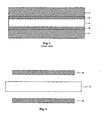
- FIG 1 illustrates a five-layer MEA with a proton exchange membrane (A) sandwiched between catalyst layers (B) that is in turn sandwiched between gas diffusion layers (C).
- PEMs perfluorosulfonic acid polymer membranes sold under the trade name Nafion by DuPont in the United States. Due to its unique perfluorinated structure, Nafion membranes are chemically stable, a factor essential for long fuel cell battery life. However, under the operating conditions of fuel cells, Nafion membranes can deform as they expand during moisture absorption and shrinkage during moisture loss. In addition, once the Nafion membrane absorbs water, the strength of the wet membranes reduces significantly. Since fuel cell batteries usually operate at high humidity, these negative effects can significantly affect the lifespan of Nafion membranes.
- CN Patent 1178482 provided a composite membrane with increased stability.
- This composite membrane is an expanded polytetrafluoroethylene (ePTFE) membrane that is completely filled with ion exchange materials where at least part of the ion exchange materials is a non-ionic polymer.
- ePTFE expanded polytetrafluoroethylene
- the MEA also contains a certain quantity of Nafion resins that also can cause the membrane to expand with moisture gain and shrink with moisture loss. This can result in changes in the interface between the catalysts and the Nafion resins, reducing the stability of the electrode.
- US Patent 6054230 introduced the use of micro-porous ePTFE membranes as the support to the catalyst layer during the fabrication of the catalyst layer.
- the catalysts/Nation dispersing solution is brushed or coated onto the ePTFE membrane. It penetrates into the pores of PTFE to form a porous composite catalyst layer which is used to form the CCMs.
- US 5,242,764 discloses a method for assembling a fuel cell.
- the catalysts used in the document are provided on one of the side surfaces, and there is no description whatsoever as to how said catalysts are provided.
- US 5,399,184 discloses a method for fabricating an electrode assembly for solid polymer electrolyte fuel cells.
- the catalysts used in the document are applied on a carbon cloth sheet or paper layer, by means of a paste composition which contains both the catalyst material (carbon particles) and a hydrophobic resin (namely polytetrafluoroethylene in example 5, and Nafion resin in example 8).
- US 5,234,777 discloses a method for fabricating a solid polymer electrolyte membrane assembly for separating anodic and cathodic backings in a gas reaction fuel cell, comprising the steps of: forming a uniform dispersion consisting essentially of a supported Pt catalyst in a perfluorosulfonate ionomer; forming a thin film of said dispersion to a Pt loading less than about 0.35 mg Pt/cm 2 ; transferring said film to a surface of a solid polymer electrolyte membrane; and providing an exchange membrane between two of the catalyst layers to form a catalyst coated membrane.
- the Nafion resin colloid and catalysts will separate resulting in the clogging of the bottom portion of the ePTFE membranes with the excessive Nafion resins and the upper portion of the membranes with the catalyst clusters.
- This uneven distribution of catalysts and Nafion resins in the micro-porous ePTFE membranes causes an inferior electrode structure, is an obstacle to proton transfer, and results in the poor performance and stability of the MEA.
- An object of this invention is to provide methods for the fabrication of catalyst coated membranes that are stable.
- Another object of this invention is to provide methods for the fabrication of catalyst coated membranes which perform well when used as part of the membrane electrode assembly in a fuel cell.
- Another object of this invention is to provide catalyst layers with membranes that are hydrophobic.
- this invention relates to fabrication methods for catalyst coated membranes that include the steps of: exposing a micro-porous membrane to a catalyst dispersing solution as described in claim 1, to form a catalyst containing micro-porous membrane; exposing said catalyst containing micro-porous membrane to a resin dispersing solution to form a catalyst layer; and placing a proton exchange membrane between two of said catalyst layers with a laminating process to form the catalyst coated membrane.
- An advantage of this invention is that catalyst coated membranes fabricated using the methods of this invention are stable.
- Another advantage of this invention is that the catalyst coated membranes fabricated with the methods of this invention perform well when used as part of the membrane electrode assembly in a fuel cell.
- Another advantage of this invention is that the catalyst coated membranes fabricated using the methods of this invention are hydrophobic.
- Figure 1 is a cross-sectional view of a five layer membrane electrode assembly.
- Figure 2 is the cross-sectional view of a catalyst coated membrane fabricated using the methods of this invention.
- Presently preferred embodiments provide for the fabrication methods for catalyst coated membranes. These methods comprise of the following steps:
- any micro-porous membrane that is used for catalyst coated membranes can be used for the micro-porous membrane.
- any types of micro-porous ePTFE membranes can be used.
- the thickness of said membranes can be 3 micrometers to 20 micrometers, preferably, 5 micrometers to 10 micrometers.
- the diameter of the pores in said micro-porous membrane can be 0.5 micrometers to 2.0 micrometers, preferably, 1 micrometer to 2 micrometers.
- the porosity of the micro-porous membrane can be 70% to 95%, preferably, 90% to 95%.
- the catalyst dispersing solution is as described in claim 1 where the weight ratio of said one or more catalysts: alcohol: water is 1 : 10 to 500: 0-50; preferably 1 : 20-200 : 1.5-20.
- the catalysts that can be used are catalysts that are commonly used for CCMs. They can be catalysts or chemicals with catalytic properties that are used in CCMs such as: nano-metal catalysts or nano-metal particles supported on carbon catalysts. Preferably, they are one or more catalysts or chemicals with catalytic properties selected from the following group: nano-platinum, nano-gold, nano-ruthenium, nano-silver, nano-cobalt, nano-platinium-ruthenium alloys, nano-platinum-cobalt alloy, nano-platinum supported on carbon, nano-gold supported on carbon, nano-ruthenium supported on carbon, nano-silver supported on carbon, nano-cobalt supported on carbon nano-platinium-ruthenium alloys supported on carbon, and nano-platinum-cobalt alloy supported on carbon.
- the alcohols in the catalyst dispersing solution can be a combination of one or more of the following: iso-propyl alcohol, ethanol and trimethylene glycol. Ethanol is preferred.
- exposing methods can be used to expose the micro-porous membrane to the catalyst dispersing solution.
- exposing methods include the coating of the catalyst dispersing solution onto the membrane or immersing the membrane into the catalyst dispersing solution.
- a preferred method is to conduct the first exposing under a vacuum of 0.01mPa to 0.1 mPa; preferably 0.04 mPa to 0.08 mPa.
- the definition of vacuum is the absolute value of the difference between the absolute pressure and the atmosphere. (The absolute pressure is less than the atmosphere).
- the quantity of catalyst dispersing solution (dispersion) used should result in 0.1 mg/cm 2 to 10 mg/cm 2 of catalyst in the catalyst containing micro-porous membrane.
- Preferred methods of uses a quantity of catalyst dispersing solution that results in 0.2mg/cm 2 to 2 mg/cm 2 of catalyst in the catalyst containing micro-porous membrane.
- the catalyst containing micro-porous membrane can be dried with commonly drying processes such as baking, air-blower drying at 30°C to 150°C. Preferred methods air blow dry said membrane at 40°C to 100°C.
- the micro-porous membrane can be supported by a support structure, such as a porous structure or a network structure, selected from the following: PET (Polyethylene terephthalate) felts, polypropylene felts, polyethylene nets, or PET non-woven fabrics.
- a support structure such as a porous structure or a network structure, selected from the following: PET (Polyethylene terephthalate) felts, polypropylene felts, polyethylene nets, or PET non-woven fabrics.
- the resin dispersing solution comprises of one or more resins and one or more solvent.
- the resins and solvents that can be used are the type of resins and solvents commonly used.
- the resin could be Nafion resins manufactured by DuPont.
- the solvent can be an alcohol solution that comprises of a combination of one or more of the following: iso-propyl alcohol, ethanol and trimethylene glycol. Ethanol is the preferred alcohol to be used.
- the concentration of said resins in said resin dispersing solution can be 0.01 wt.% to 3 wt.%, preferably, 0.02 wt.% to 2.5 wt.%
- exposing methods include the coating of the resin dispersing on the membrane or immersing the membrane in the resin dispersing solution. Coating is the preferred method.
- a preferred method is conducting the second exposing under a vacuum of 0.01mPa to 0.1 mPa; preferably 0.04 mPa to 0.08 mPa.
- the quantity of resin dispersing solution used should result in 0.03 mg/cm 2 to 20 mg/cm 2 of resin in the micro-porous membrane.
- Preferred methods of uses a quantity of resin dispersing solution that result in 0.2 to 7 mg/cm 2 of resin in the micro-porous membrane.
- the catalyst layer micro-porous membrane can be dried with commonly drying process such as baking, air-blower drying at 25°C to 200°C. Preferred methods air blow dry said membrane at 50°C to 150°C.
- the catalyst coated membrane may be fabricated with a laminating process by sandwiching the proton exchange membrane between two catalyst layers and press bonding the layers. If there is a support for the micro-porous membrane, this support is removed prior to the placing step/laminating step.
- a hot plate press method or dual-roller hot-press method can be used to solidly bond together the catalyst layers and the proton exchange membrane at temperatures 100°C to 200 °C; and pressure of 0.1 mPa to 10 mPa. Preferably, temperature at 120°C to 170°C; and pressure at 0.5 mPa to 6 mPa.
- the PEM that are commonly used can be used in the methods of this invention.
- Examples of commercially available PEM are the Nafion membranes from DuPont, including the Nafion 112 film, Nafion 115 film, Nafion 117 film and Nafion 1035 film.
- the PTFE/Nafion composite membranes disclosed in CN Patent 1178482A can also be used.
- Figure 2 is a cross-sectional view of a CCM that is fabricated using the methods of this invention where the two catalyst layers ((B) are sandwiched between the PEM (A).
- the fabrication methods of this invention provide filling process to uniformly fill the catalysts and resin throughout the pores of the micro-porous membranes in the catalyst layers. These micro-porous membranes are hydrophobic and easily discharge water when necessary. Therefore, membrane electrode assemblies with catalyst coated membranes fabricated using the methods of this invention are stable and perform well during fuel cell operation.
- One method for fabricating a catalyst containing micro-porous membrane includes the following steps:
- One method for fabricating a catalyst layer include the following steps:
- the fabrication of the CCM using catalyst layers that is fabricated by the method described above includes the following steps:
- One method for fabricating a catalyst containing micro-porous membrane includes the following steps:
- One method for fabricating a catalyst layer include the following steps:
- the fabrication of the CCM using catalyst layers that is fabricated by the method described above includes the following steps:
Landscapes
- Chemical & Material Sciences (AREA)
- Chemical Kinetics & Catalysis (AREA)
- Engineering & Computer Science (AREA)
- Manufacturing & Machinery (AREA)
- Electrochemistry (AREA)
- General Chemical & Material Sciences (AREA)
- Inorganic Chemistry (AREA)
- Materials Engineering (AREA)
- Physics & Mathematics (AREA)
- Sustainable Energy (AREA)
- Sustainable Development (AREA)
- Dispersion Chemistry (AREA)
- Thermal Sciences (AREA)
- Life Sciences & Earth Sciences (AREA)
- Organic Chemistry (AREA)
- Nanotechnology (AREA)
- Metallurgy (AREA)
- Crystallography & Structural Chemistry (AREA)
- Composite Materials (AREA)
- Condensed Matter Physics & Semiconductors (AREA)
- General Physics & Mathematics (AREA)
- Catalysts (AREA)
- Inert Electrodes (AREA)
- Fuel Cell (AREA)
- Application Of Or Painting With Fluid Materials (AREA)
Claims (13)
- Procédé de fabrication de membranes revêtues d'un catalyseur, comprenant les étapes suivantes :première exposition d'une membrane microporeuse à une solution de dispersion de catalyseur pour former une membrane microporeuse contenant un catalyseur;seconde exposition de ladite membrane microporeuse contenant un catalyseur à une solution de dispersion de résine pour former une couche de catalyseur; etplacement d'une membrane échangeuse de protons entre deux desdites couches de catalyseur pour former ladite membrane revêtue d'un catalyseur,dans lequel la solution de dispersion de catalyseur consiste en 10 à 500 parties en poids d'alcool et 0 à 50 parties en poids d'eau pour une partie en poids de catalyseur.
- Procédé selon la revendication 1, dans lequel l'épaisseur de ladite membrane microporeuse est de 3 micromètres à 20 micromètres, le diamètre des pores dans ladite membrane microporeuse est de 0,5 à 2,0 micromètres, et la porosité de ladite membrane microporeuse est de 70 % à 95 %.
- Procédé selon la revendication 1, dans lequel ledit catalyseur est un ou plusieurs produits chimiques sélectionnés ayant des propriétés catalytiques, choisis dans le groupe consistant en : le nano-platine, le nano-or, le nano-ruthénium, le nano-argent, le nano-cobalt, les alliages de nano-platine-ruthénium, l'alliage de nano-platine-cobalt, le nano-platine supporté sur du carbone, le nano-or supporté sur du carbone, le nano-ruthénium supporté sur du carbone, le nano-argent supporté sur du carbone, le nano-cobalt supporté sur du carbone, les alliages de nano-platine-ruthénium supportés sur du carbone et l'alliage de nano-platine-cobalt supporté sur du carbone.
- Procédé selon la revendication 1, dans lequel ladite première étape d'exposition est le revêtement de ladite solution de dispersion de catalyseur sur ladite membrane microporeuse.
- Procédé selon la revendication 1, dans lequel ladite première étape d'exposition est conduite sous un vide de 0,01 mPa à 0,1 mPa.
- Procédé selon la revendication 1, dans lequel la quantité de catalyseur dans ladite membrane microporeuse contenant un catalyseur est de 0,1 mg/cm2 à 10 mg/cm2 .
- Procédé selon la revendication 1, dans lequel, après ladite première étape d'exposition, l'étape suivante est ajoutée :le séchage de ladite membrane microporeuse contenant un catalyseur à 30°C à 150°C.
- Procédé selon la revendication 1, dans lequel ladite solution de dispersion de résine comprend une ou plusieurs résines et un ou plusieurs solvants et la concentration desdites résines dans ladite solution de dispersion de résine est de 0,01% en poids à 3 % en poids.
- Procédé selon la revendication 1, dans lequel ladite solution de dispersion de résine comprend une ou plusieurs résines et la concentration de résine dans ladite membrane microporeuse est de 0,03 mg/cm2 à 20 mg/cm2.
- Procédé selon la revendication 1, dans lequel ladite seconde étape d'exposition est le revêtement de ladite solution de dispersion de résine sur ladite membrane microporeuse contenant un catalyseur sous un vide de 0,01 mPa à 0,1 mPa.
- Procédé selon la revendication 10, dans lequel, après ladite seconde étape d'exposition, l'étape suivante est ajoutée :le séchage de ladite couche de catalyseur à 25°C à 200°C.
- Procédé selon la revendication 1, dans lequel ladite membrane microporeuse est supportée par un support choisi dans le groupe consistant en : les feutres PET, les feutres de polypropylène, les filets de polyéthylène ou les étoffes non tissées PET et ledit support est retiré avant ladite étape de placement.
- Procédé selon la revendication 1, dans lequel, après ladite étape de placement, la membrane revêtue d'un catalyseur est soit pressée à chaud, soit pressée à chaud par doubles rouleaux.
Applications Claiming Priority (2)
| Application Number | Priority Date | Filing Date | Title |
|---|---|---|---|
| CNB2005101301011A CN100515566C (zh) | 2005-12-12 | 2005-12-12 | 一种催化剂涂层膜的制备方法 |
| PCT/CN2006/003380 WO2007068199A1 (fr) | 2005-12-12 | 2006-12-12 | Procedes de fabrication de membranes revetues d'un catalyseur |
Publications (3)
| Publication Number | Publication Date |
|---|---|
| EP1963013A1 EP1963013A1 (fr) | 2008-09-03 |
| EP1963013A4 EP1963013A4 (fr) | 2009-01-07 |
| EP1963013B1 true EP1963013B1 (fr) | 2010-03-17 |
Family
ID=38139707
Family Applications (1)
| Application Number | Title | Priority Date | Filing Date |
|---|---|---|---|
| EP06828302A Ceased EP1963013B1 (fr) | 2005-12-12 | 2006-12-12 | Procedes de fabrication de membranes revetues d'un catalyseur |
Country Status (8)
| Country | Link |
|---|---|
| US (2) | US20070134407A1 (fr) |
| EP (1) | EP1963013B1 (fr) |
| JP (1) | JP2009518817A (fr) |
| KR (1) | KR100978117B1 (fr) |
| CN (1) | CN100515566C (fr) |
| AT (1) | ATE460984T1 (fr) |
| DE (1) | DE602006013036D1 (fr) |
| WO (1) | WO2007068199A1 (fr) |
Families Citing this family (14)
| Publication number | Priority date | Publication date | Assignee | Title |
|---|---|---|---|---|
| US20100285388A1 (en) * | 2007-05-18 | 2010-11-11 | Sim Composites Inc. | Catalyst-coated proton exchange membrane and process of producing same |
| KR20090058406A (ko) * | 2007-12-04 | 2009-06-09 | 한화석유화학 주식회사 | 연료전지용 독립 전극 촉매 층 및 이를 이용한 막-전극접합체의 제조방법 |
| WO2010036234A1 (fr) * | 2008-09-23 | 2010-04-01 | Utc Power Corporation | Pile à combustible utilisant un agent d'étanchéité durcissable par uv |
| CZ2009152A3 (cs) * | 2009-03-10 | 2010-11-10 | Elmarco S.R.O. | Vrstvený filtracní materiál a zarízení pro cištení plynného média |
| US9735441B2 (en) | 2010-09-30 | 2017-08-15 | Audi Ag | Hot pressed, direct deposited catalyst layer |
| JP2016129085A (ja) * | 2013-04-26 | 2016-07-14 | 日産自動車株式会社 | ガス拡散電極体、その製造方法ならびにこれを用いる燃料電池用膜電極接合体および燃料電池 |
| US20170200954A1 (en) * | 2015-09-16 | 2017-07-13 | Uti Limited Partnership | Fuel cells constructed from self-supporting catalyst layers and/or self-supporting microporous layers |
| US11535017B2 (en) | 2017-04-04 | 2022-12-27 | W. L. Gore & Associates Gmbh | Dielectric composite with reinforced elastomer and integrate electrode |
| CN107961619B (zh) * | 2017-12-11 | 2021-02-09 | 中材科技膜材料(山东)有限公司 | 多功能覆膜滤料的制备方法 |
| CN109921034B (zh) * | 2017-12-13 | 2021-04-27 | 中国科学院大连化学物理研究所 | 一种阴离子交换膜燃料电池分级有序催化层的制备方法及应用 |
| US11684702B2 (en) * | 2019-05-24 | 2023-06-27 | Conmed Corporation | Gap control in electrosurgical instruments using expanded polytetrafluoroethylene |
| CN115193625B (zh) * | 2022-08-12 | 2024-09-17 | 上海明天观谛氢能科技有限公司 | 一种燃料电池膜电极的喷涂夹具及喷涂方法 |
| WO2025048510A1 (fr) * | 2023-09-01 | 2025-03-06 | 주식회사 엘지화학 | Séparateur et cellule électrochimique le comprenant |
| CN117400503A (zh) * | 2023-10-27 | 2024-01-16 | 国家电投集团氢能科技发展有限公司 | 质子交换膜、制备方法及其应用 |
Family Cites Families (22)
| Publication number | Priority date | Publication date | Assignee | Title |
|---|---|---|---|---|
| US1276633A (en) * | 1916-01-25 | 1918-08-20 | Charles Owen Forbes | Permutation-lock. |
| US5234777A (en) * | 1991-02-19 | 1993-08-10 | The Regents Of The University Of California | Membrane catalyst layer for fuel cells |
| US5242764A (en) * | 1991-12-17 | 1993-09-07 | Bcs Technology, Inc. | Near ambient, unhumidified solid polymer fuel cell |
| US5399184A (en) * | 1992-05-01 | 1995-03-21 | Chlorine Engineers Corp., Ltd. | Method for fabricating gas diffusion electrode assembly for fuel cells |
| US6054230A (en) | 1994-12-07 | 2000-04-25 | Japan Gore-Tex, Inc. | Ion exchange and electrode assembly for an electrochemical cell |
| JP3481010B2 (ja) * | 1995-05-30 | 2003-12-22 | ジャパンゴアテックス株式会社 | 高分子固体電解質膜/電極一体成形体及びその製法 |
| JPH1171692A (ja) * | 1997-07-01 | 1999-03-16 | Fuji Electric Co Ltd | イオン交換膜と電極の接合体の製作方法および製作装置 |
| KR100263992B1 (ko) * | 1998-02-23 | 2000-08-16 | 손재익 | 고체고분자 연료전지의 고분자막/전극 접합체 제조방법 |
| GB9805815D0 (en) * | 1998-03-19 | 1998-05-13 | Johnson Matthey Plc | Manufacturing process |
| JP2001160406A (ja) * | 1999-12-06 | 2001-06-12 | Toshiba Corp | 固体高分子型燃料電池の電極およびその製造方法 |
| US6524736B1 (en) * | 2000-10-18 | 2003-02-25 | General Motors Corporation | Methods of preparing membrane electrode assemblies |
| JP2003132900A (ja) * | 2001-10-22 | 2003-05-09 | Ube Ind Ltd | 金属分散炭素膜構造体、燃料電池用電極、電極接合体、及び燃料電池 |
| US6855660B2 (en) * | 2001-11-07 | 2005-02-15 | De Nora Elettrodi S.P.A. | Rhodium electrocatalyst and method of preparation |
| JP2003317729A (ja) * | 2002-04-26 | 2003-11-07 | Ube Ind Ltd | 多孔質黒鉛フィルムを用いた燃料電池用電極、膜−電極接合体及び燃料電池 |
| KR100480782B1 (ko) * | 2002-10-26 | 2005-04-07 | 삼성에스디아이 주식회사 | 연료전지 단위체, 그 제조방법 및 상기 연료전지 단위체를채용한 연료전지 |
| US7303835B2 (en) * | 2003-01-15 | 2007-12-04 | General Motors Corporation | Diffusion media, fuel cells, and fuel cell powered systems |
| JP2004335459A (ja) * | 2003-04-18 | 2004-11-25 | Ube Ind Ltd | 金属担持多孔質炭素膜、燃料電池用電極及びそれを用いた燃料電池 |
| CN100401563C (zh) * | 2003-07-02 | 2008-07-09 | 中山大学 | 一种质子交换膜燃料电池膜电极组件的制备方法 |
| US7351444B2 (en) * | 2003-09-08 | 2008-04-01 | Intematix Corporation | Low platinum fuel cell catalysts and method for preparing the same |
| CN100521313C (zh) * | 2003-10-27 | 2009-07-29 | 中国科学院大连化学物理研究所 | 用于质子交换膜燃料电池的膜电极结构及其制备方法 |
| CN1564353A (zh) * | 2004-03-25 | 2005-01-12 | 天津大学 | 液态进料直接甲醇燃料电池的膜电极及其制备工艺 |
| JP2005285496A (ja) * | 2004-03-29 | 2005-10-13 | Toyota Motor Corp | 燃料電池用膜電極複合体およびそれを備えた燃料電池 |
-
2005
- 2005-12-12 CN CNB2005101301011A patent/CN100515566C/zh not_active Expired - Fee Related
-
2006
- 2006-12-12 US US11/637,389 patent/US20070134407A1/en not_active Abandoned
- 2006-12-12 DE DE602006013036T patent/DE602006013036D1/de active Active
- 2006-12-12 WO PCT/CN2006/003380 patent/WO2007068199A1/fr not_active Ceased
- 2006-12-12 US US12/096,866 patent/US20080305250A1/en not_active Abandoned
- 2006-12-12 JP JP2008544740A patent/JP2009518817A/ja active Pending
- 2006-12-12 EP EP06828302A patent/EP1963013B1/fr not_active Ceased
- 2006-12-12 KR KR1020087016612A patent/KR100978117B1/ko not_active Expired - Fee Related
- 2006-12-12 AT AT06828302T patent/ATE460984T1/de not_active IP Right Cessation
Also Published As
| Publication number | Publication date |
|---|---|
| CN100515566C (zh) | 2009-07-22 |
| KR100978117B1 (ko) | 2010-08-25 |
| US20070134407A1 (en) | 2007-06-14 |
| WO2007068199A1 (fr) | 2007-06-21 |
| DE602006013036D1 (de) | 2010-04-29 |
| JP2009518817A (ja) | 2009-05-07 |
| CN1981934A (zh) | 2007-06-20 |
| ATE460984T1 (de) | 2010-04-15 |
| US20080305250A1 (en) | 2008-12-11 |
| EP1963013A4 (fr) | 2009-01-07 |
| EP1963013A1 (fr) | 2008-09-03 |
| KR20080080361A (ko) | 2008-09-03 |
Similar Documents
| Publication | Publication Date | Title |
|---|---|---|
| US5716437A (en) | Materials for use in electrode manufacture | |
| US7141270B2 (en) | Method for the production of membrane electrode assemblies for fuel cells | |
| CN100452509C (zh) | 催化层支撑质子交换膜燃料电池复合膜电极及其制备方法 | |
| CN103367762B (zh) | 具有整合的增强层的电极组件 | |
| JP2011029171A (ja) | ガス拡散電極およびその製造方法、ならびに膜電極接合体およびその製造方法 | |
| US9780399B2 (en) | Electrode assembly with integrated reinforcement layer | |
| JP2008186798A (ja) | 電解質膜−電極接合体 | |
| US20090169957A1 (en) | Porous material for fuel cell electrolyte membrane, method for producing the same, electrolyte membrane for solid polymer fuel cell, membrane electrode assembly (mea), and fuel cell | |
| US20080305250A1 (en) | Fabrication Methods for Catalyst Coated Membranes | |
| CN101557001A (zh) | 一种燃料电池膜电极及其制备方法 | |
| KR20230075790A (ko) | 다층 강화 복합 전해질막 및 이의 제조방법 | |
| CN111584880B (zh) | 一种低铂质子交换膜燃料电池膜电极及其制备方法 | |
| US9520610B2 (en) | Method of manufacturing 5-layer MEA having improved electrical conductivity | |
| JP5286887B2 (ja) | 固体高分子型燃料電池用補強シート付き膜・電極接合体およびその製造方法 | |
| US11424467B2 (en) | Method for manufacturing membrane electrode assembly, and stack | |
| CN114864958A (zh) | 无质子交换膜的燃料电池用电极组件及其制备方法、燃料电池 | |
| CN100444434C (zh) | 具有水调节能力的膜电极及制备方法 | |
| JP2002203568A (ja) | 膜/電極接合体及びそれを用いた燃料電池 | |
| CA2668895A1 (fr) | Couches d'electrocatalyseurs pour piles a combustible et leurs procedes de fabrication | |
| CN100486006C (zh) | 一种质子交换膜燃料电池的膜电极制备方法 | |
| JP5609475B2 (ja) | 電極触媒層、電極触媒層の製造方法、この電極触媒層を用いた固体高分子形燃料電池 | |
| RU2793458C1 (ru) | Электродная сборка для топливного элемента без протонообменной мембраны, способ ее получения и топливный элемент | |
| CA3149815C (fr) | Assemblage d'electrode pour une pile a combustible sans membrane d'echange de protons, methode de preparation et pile a combustible | |
| CN100568595C (zh) | 一种催化剂涂层膜的制备方法 | |
| EP4060776A1 (fr) | Ensemble électrode pour pile à combustible sans membrane échangeuse de protons et son procédé de préparation, et pile à combustible |
Legal Events
| Date | Code | Title | Description |
|---|---|---|---|
| PUAI | Public reference made under article 153(3) epc to a published international application that has entered the european phase |
Free format text: ORIGINAL CODE: 0009012 |
|
| 17P | Request for examination filed |
Effective date: 20080704 |
|
| AK | Designated contracting states |
Kind code of ref document: A1 Designated state(s): AT BE BG CH CY CZ DE DK EE ES FI FR GB GR HU IE IS IT LI LT LU LV MC NL PL PT RO SE SI SK TR |
|
| A4 | Supplementary search report drawn up and despatched |
Effective date: 20081204 |
|
| RIC1 | Information provided on ipc code assigned before grant |
Ipc: B01J 23/75 20060101ALI20081128BHEP Ipc: B01J 23/38 20060101ALI20081128BHEP Ipc: C25B 9/00 20060101ALI20081128BHEP Ipc: H01M 4/88 20060101ALI20081128BHEP Ipc: B01D 71/32 20060101ALI20081128BHEP Ipc: B01D 67/00 20060101ALI20081128BHEP Ipc: B01D 69/14 20060101ALI20081128BHEP Ipc: B01J 37/025 20060101AFI20070816BHEP Ipc: B01D 71/36 20060101ALI20081128BHEP |
|
| 17Q | First examination report despatched |
Effective date: 20090123 |
|
| GRAP | Despatch of communication of intention to grant a patent |
Free format text: ORIGINAL CODE: EPIDOSNIGR1 |
|
| DAX | Request for extension of the european patent (deleted) | ||
| GRAS | Grant fee paid |
Free format text: ORIGINAL CODE: EPIDOSNIGR3 |
|
| GRAA | (expected) grant |
Free format text: ORIGINAL CODE: 0009210 |
|
| AK | Designated contracting states |
Kind code of ref document: B1 Designated state(s): AT BE BG CH CY CZ DE DK EE ES FI FR GB GR HU IE IS IT LI LT LU LV MC NL PL PT RO SE SI SK TR |
|
| REG | Reference to a national code |
Ref country code: GB Ref legal event code: FG4D |
|
| REG | Reference to a national code |
Ref country code: CH Ref legal event code: EP |
|
| REG | Reference to a national code |
Ref country code: IE Ref legal event code: FG4D |
|
| REF | Corresponds to: |
Ref document number: 602006013036 Country of ref document: DE Date of ref document: 20100429 Kind code of ref document: P |
|
| REG | Reference to a national code |
Ref country code: NL Ref legal event code: VDEP Effective date: 20100317 |
|
| PG25 | Lapsed in a contracting state [announced via postgrant information from national office to epo] |
Ref country code: LT Free format text: LAPSE BECAUSE OF FAILURE TO SUBMIT A TRANSLATION OF THE DESCRIPTION OR TO PAY THE FEE WITHIN THE PRESCRIBED TIME-LIMIT Effective date: 20100317 |
|
| LTIE | Lt: invalidation of european patent or patent extension |
Effective date: 20100317 |
|
| PG25 | Lapsed in a contracting state [announced via postgrant information from national office to epo] |
Ref country code: LV Free format text: LAPSE BECAUSE OF FAILURE TO SUBMIT A TRANSLATION OF THE DESCRIPTION OR TO PAY THE FEE WITHIN THE PRESCRIBED TIME-LIMIT Effective date: 20100317 Ref country code: AT Free format text: LAPSE BECAUSE OF FAILURE TO SUBMIT A TRANSLATION OF THE DESCRIPTION OR TO PAY THE FEE WITHIN THE PRESCRIBED TIME-LIMIT Effective date: 20100317 Ref country code: FI Free format text: LAPSE BECAUSE OF FAILURE TO SUBMIT A TRANSLATION OF THE DESCRIPTION OR TO PAY THE FEE WITHIN THE PRESCRIBED TIME-LIMIT Effective date: 20100317 Ref country code: PL Free format text: LAPSE BECAUSE OF FAILURE TO SUBMIT A TRANSLATION OF THE DESCRIPTION OR TO PAY THE FEE WITHIN THE PRESCRIBED TIME-LIMIT Effective date: 20100317 Ref country code: SI Free format text: LAPSE BECAUSE OF FAILURE TO SUBMIT A TRANSLATION OF THE DESCRIPTION OR TO PAY THE FEE WITHIN THE PRESCRIBED TIME-LIMIT Effective date: 20100317 |
|
| PG25 | Lapsed in a contracting state [announced via postgrant information from national office to epo] |
Ref country code: NL Free format text: LAPSE BECAUSE OF FAILURE TO SUBMIT A TRANSLATION OF THE DESCRIPTION OR TO PAY THE FEE WITHIN THE PRESCRIBED TIME-LIMIT Effective date: 20100317 Ref country code: RO Free format text: LAPSE BECAUSE OF FAILURE TO SUBMIT A TRANSLATION OF THE DESCRIPTION OR TO PAY THE FEE WITHIN THE PRESCRIBED TIME-LIMIT Effective date: 20100317 Ref country code: ES Free format text: LAPSE BECAUSE OF FAILURE TO SUBMIT A TRANSLATION OF THE DESCRIPTION OR TO PAY THE FEE WITHIN THE PRESCRIBED TIME-LIMIT Effective date: 20100628 Ref country code: GR Free format text: LAPSE BECAUSE OF FAILURE TO SUBMIT A TRANSLATION OF THE DESCRIPTION OR TO PAY THE FEE WITHIN THE PRESCRIBED TIME-LIMIT Effective date: 20100618 Ref country code: SE Free format text: LAPSE BECAUSE OF FAILURE TO SUBMIT A TRANSLATION OF THE DESCRIPTION OR TO PAY THE FEE WITHIN THE PRESCRIBED TIME-LIMIT Effective date: 20100317 Ref country code: BE Free format text: LAPSE BECAUSE OF FAILURE TO SUBMIT A TRANSLATION OF THE DESCRIPTION OR TO PAY THE FEE WITHIN THE PRESCRIBED TIME-LIMIT Effective date: 20100317 Ref country code: CY Free format text: LAPSE BECAUSE OF FAILURE TO SUBMIT A TRANSLATION OF THE DESCRIPTION OR TO PAY THE FEE WITHIN THE PRESCRIBED TIME-LIMIT Effective date: 20100317 Ref country code: EE Free format text: LAPSE BECAUSE OF FAILURE TO SUBMIT A TRANSLATION OF THE DESCRIPTION OR TO PAY THE FEE WITHIN THE PRESCRIBED TIME-LIMIT Effective date: 20100317 |
|
| PG25 | Lapsed in a contracting state [announced via postgrant information from national office to epo] |
Ref country code: SK Free format text: LAPSE BECAUSE OF FAILURE TO SUBMIT A TRANSLATION OF THE DESCRIPTION OR TO PAY THE FEE WITHIN THE PRESCRIBED TIME-LIMIT Effective date: 20100317 Ref country code: IS Free format text: LAPSE BECAUSE OF FAILURE TO SUBMIT A TRANSLATION OF THE DESCRIPTION OR TO PAY THE FEE WITHIN THE PRESCRIBED TIME-LIMIT Effective date: 20100717 Ref country code: CZ Free format text: LAPSE BECAUSE OF FAILURE TO SUBMIT A TRANSLATION OF THE DESCRIPTION OR TO PAY THE FEE WITHIN THE PRESCRIBED TIME-LIMIT Effective date: 20100317 Ref country code: BG Free format text: LAPSE BECAUSE OF FAILURE TO SUBMIT A TRANSLATION OF THE DESCRIPTION OR TO PAY THE FEE WITHIN THE PRESCRIBED TIME-LIMIT Effective date: 20100617 |
|
| PLBE | No opposition filed within time limit |
Free format text: ORIGINAL CODE: 0009261 |
|
| STAA | Information on the status of an ep patent application or granted ep patent |
Free format text: STATUS: NO OPPOSITION FILED WITHIN TIME LIMIT |
|
| PG25 | Lapsed in a contracting state [announced via postgrant information from national office to epo] |
Ref country code: DK Free format text: LAPSE BECAUSE OF FAILURE TO SUBMIT A TRANSLATION OF THE DESCRIPTION OR TO PAY THE FEE WITHIN THE PRESCRIBED TIME-LIMIT Effective date: 20100317 Ref country code: PT Free format text: LAPSE BECAUSE OF FAILURE TO SUBMIT A TRANSLATION OF THE DESCRIPTION OR TO PAY THE FEE WITHIN THE PRESCRIBED TIME-LIMIT Effective date: 20100719 |
|
| 26N | No opposition filed |
Effective date: 20101220 |
|
| PG25 | Lapsed in a contracting state [announced via postgrant information from national office to epo] |
Ref country code: IT Free format text: LAPSE BECAUSE OF FAILURE TO SUBMIT A TRANSLATION OF THE DESCRIPTION OR TO PAY THE FEE WITHIN THE PRESCRIBED TIME-LIMIT Effective date: 20100317 |
|
| PG25 | Lapsed in a contracting state [announced via postgrant information from national office to epo] |
Ref country code: MC Free format text: LAPSE BECAUSE OF NON-PAYMENT OF DUE FEES Effective date: 20101231 |
|
| REG | Reference to a national code |
Ref country code: CH Ref legal event code: PL |
|
| PG25 | Lapsed in a contracting state [announced via postgrant information from national office to epo] |
Ref country code: CH Free format text: LAPSE BECAUSE OF NON-PAYMENT OF DUE FEES Effective date: 20101231 Ref country code: IE Free format text: LAPSE BECAUSE OF NON-PAYMENT OF DUE FEES Effective date: 20101212 Ref country code: LI Free format text: LAPSE BECAUSE OF NON-PAYMENT OF DUE FEES Effective date: 20101231 |
|
| PG25 | Lapsed in a contracting state [announced via postgrant information from national office to epo] |
Ref country code: LU Free format text: LAPSE BECAUSE OF NON-PAYMENT OF DUE FEES Effective date: 20101212 Ref country code: HU Free format text: LAPSE BECAUSE OF FAILURE TO SUBMIT A TRANSLATION OF THE DESCRIPTION OR TO PAY THE FEE WITHIN THE PRESCRIBED TIME-LIMIT Effective date: 20100918 |
|
| PG25 | Lapsed in a contracting state [announced via postgrant information from national office to epo] |
Ref country code: TR Free format text: LAPSE BECAUSE OF FAILURE TO SUBMIT A TRANSLATION OF THE DESCRIPTION OR TO PAY THE FEE WITHIN THE PRESCRIBED TIME-LIMIT Effective date: 20100317 |
|
| REG | Reference to a national code |
Ref country code: FR Ref legal event code: PLFP Year of fee payment: 10 |
|
| REG | Reference to a national code |
Ref country code: FR Ref legal event code: PLFP Year of fee payment: 11 |
|
| REG | Reference to a national code |
Ref country code: FR Ref legal event code: PLFP Year of fee payment: 12 |
|
| PGFP | Annual fee paid to national office [announced via postgrant information from national office to epo] |
Ref country code: DE Payment date: 20211210 Year of fee payment: 16 Ref country code: GB Payment date: 20211221 Year of fee payment: 16 Ref country code: FR Payment date: 20211224 Year of fee payment: 16 |
|
| REG | Reference to a national code |
Ref country code: DE Ref legal event code: R119 Ref document number: 602006013036 Country of ref document: DE |
|
| GBPC | Gb: european patent ceased through non-payment of renewal fee |
Effective date: 20221212 |
|
| PG25 | Lapsed in a contracting state [announced via postgrant information from national office to epo] |
Ref country code: GB Free format text: LAPSE BECAUSE OF NON-PAYMENT OF DUE FEES Effective date: 20221212 Ref country code: DE Free format text: LAPSE BECAUSE OF NON-PAYMENT OF DUE FEES Effective date: 20230701 |
|
| PG25 | Lapsed in a contracting state [announced via postgrant information from national office to epo] |
Ref country code: FR Free format text: LAPSE BECAUSE OF NON-PAYMENT OF DUE FEES Effective date: 20221231 |