EP1964631A2 - Plaque de coupe pour outils de traitement d'un ensemble de roues - Google Patents
Plaque de coupe pour outils de traitement d'un ensemble de roues Download PDFInfo
- Publication number
- EP1964631A2 EP1964631A2 EP20080102011 EP08102011A EP1964631A2 EP 1964631 A2 EP1964631 A2 EP 1964631A2 EP 20080102011 EP20080102011 EP 20080102011 EP 08102011 A EP08102011 A EP 08102011A EP 1964631 A2 EP1964631 A2 EP 1964631A2
- Authority
- EP
- European Patent Office
- Prior art keywords
- cutting
- region
- cutting edge
- sections
- ribs
- Prior art date
- Legal status (The legal status is an assumption and is not a legal conclusion. Google has not performed a legal analysis and makes no representation as to the accuracy of the status listed.)
- Withdrawn
Links
- 238000005520 cutting process Methods 0.000 title claims abstract description 68
- 230000000630 rising effect Effects 0.000 claims abstract description 4
- 230000001174 ascending effect Effects 0.000 claims description 14
- 238000007373 indentation Methods 0.000 claims description 14
- 238000003754 machining Methods 0.000 claims description 6
- 230000015572 biosynthetic process Effects 0.000 description 8
- 230000002349 favourable effect Effects 0.000 description 7
- 230000008901 benefit Effects 0.000 description 2
- 230000008859 change Effects 0.000 description 2
- 230000000694 effects Effects 0.000 description 2
- 238000005096 rolling process Methods 0.000 description 2
- 229910000831 Steel Inorganic materials 0.000 description 1
- 230000009471 action Effects 0.000 description 1
- 230000001419 dependent effect Effects 0.000 description 1
- 238000005242 forging Methods 0.000 description 1
- 230000007246 mechanism Effects 0.000 description 1
- 238000000034 method Methods 0.000 description 1
- 230000008569 process Effects 0.000 description 1
- 238000007493 shaping process Methods 0.000 description 1
- 239000010959 steel Substances 0.000 description 1
- 238000004804 winding Methods 0.000 description 1
Images
Classifications
-
- B—PERFORMING OPERATIONS; TRANSPORTING
- B23—MACHINE TOOLS; METAL-WORKING NOT OTHERWISE PROVIDED FOR
- B23B—TURNING; BORING
- B23B27/00—Tools for turning or boring machines; Tools of a similar kind in general; Accessories therefor
- B23B27/14—Cutting tools of which the bits or tips or cutting inserts are of special material
- B23B27/16—Cutting tools of which the bits or tips or cutting inserts are of special material with exchangeable cutting bits or cutting inserts, e.g. able to be clamped
- B23B27/1625—Cutting tools of which the bits or tips or cutting inserts are of special material with exchangeable cutting bits or cutting inserts, e.g. able to be clamped with plate-like cutting inserts of special shape clamped by a clamping member acting almost perpendicularly on the chip-forming plane
- B23B27/164—Cutting tools of which the bits or tips or cutting inserts are of special material with exchangeable cutting bits or cutting inserts, e.g. able to be clamped with plate-like cutting inserts of special shape clamped by a clamping member acting almost perpendicularly on the chip-forming plane characterised by having a special shape
-
- B—PERFORMING OPERATIONS; TRANSPORTING
- B23—MACHINE TOOLS; METAL-WORKING NOT OTHERWISE PROVIDED FOR
- B23B—TURNING; BORING
- B23B2200/00—Details of cutting inserts
- B23B2200/04—Overall shape
- B23B2200/0461—Round
-
- B—PERFORMING OPERATIONS; TRANSPORTING
- B23—MACHINE TOOLS; METAL-WORKING NOT OTHERWISE PROVIDED FOR
- B23B—TURNING; BORING
- B23B2200/00—Details of cutting inserts
- B23B2200/08—Rake or top surfaces
- B23B2200/085—Rake or top surfaces discontinuous
-
- B—PERFORMING OPERATIONS; TRANSPORTING
- B23—MACHINE TOOLS; METAL-WORKING NOT OTHERWISE PROVIDED FOR
- B23B—TURNING; BORING
- B23B2200/00—Details of cutting inserts
- B23B2200/08—Rake or top surfaces
- B23B2200/086—Rake or top surfaces with one or more grooves
- B23B2200/087—Rake or top surfaces with one or more grooves for chip breaking
-
- B—PERFORMING OPERATIONS; TRANSPORTING
- B23—MACHINE TOOLS; METAL-WORKING NOT OTHERWISE PROVIDED FOR
- B23B—TURNING; BORING
- B23B2200/00—Details of cutting inserts
- B23B2200/32—Chip breaking or chip evacuation
- B23B2200/321—Chip breaking or chip evacuation by chip breaking projections
-
- B—PERFORMING OPERATIONS; TRANSPORTING
- B23—MACHINE TOOLS; METAL-WORKING NOT OTHERWISE PROVIDED FOR
- B23B—TURNING; BORING
- B23B2200/00—Details of cutting inserts
- B23B2200/32—Chip breaking or chip evacuation
- B23B2200/323—Chip breaking or chip evacuation by chip breaking depressions
Definitions
- the invention relates to a cutting plate for machining of particular rolled wheels such as railway wheels, having a top surface, a base and a top surface and bottom surface connecting open area, the cutting plate formed in plan view with a circular, circumference defining and defined by the top surface and an adjacent free surface cutting edge and has a sloping area and an ascending area between the cutting edge and a disk center.
- Wheels for rail vehicles such as railway wheels usually consist of a steel which is at least externally hardened in order to be highly resistant to wear. When creating these wheels usually rolling or forging processes are applied, the wheels are brought into a near-net shape. A desired final contour of a wheel with tolerances of a few tenths of a millimeter (mm) is created in a subsequent step by turning.
- mm millimeter
- a rotating processing of railway wheels which can have considerable dimensions of, for example, up to 1200 mm, takes place in dedicated machine rooms.
- the wheel In the rotary machining, the wheel is clamped and rotated and employed to the rotating wheel a cutting tool or a cutting plate.
- the equipped with the cutting tool is doing along the Tozu.den surfaces of the wheel, z. B. a tread, moved forward.
- Turning wheels for rail vehicles involves the formation of endless chips, which are a significant problem. Endless chips, which are due to insufficient Spanbruch Struktur, can take a length of several meters. These chips are wound around the rotating axle of the wheel receptacle, rotate with the machined wheel without breaking and present a great safety hazard to the operator. Moreover, these endless chips can result in tool failure and machine downtime.
- an insert according to the invention is of advantage that when machining wheels, especially railway wheels, regardless of the feed of the tool or the cutting plate and regardless of a thickness of the chips to be cut always a favorable chip breakage with shorter chips than previously achieved. Due to this favorable chip formation, the risk of winding chips around the rotating wheel is at least largely avoided.
- the recesses in the sloping region can be set up to the cutting edge for an excellent cutting action, so that in extreme cases a wavy cutting edge in a lateral view is given, so it has proven useful if the indentations are spaced from the cutting edge.
- the cutting edge is then less susceptible to brittleness without significantly affecting cutting performance. It is preferred that the indentations to the cutting edge have a distance of less than 0.7 mm, because then both a good chip breaking is achieved, as well as a good cutting performance with low tendency to vibration of the insert is given.
- the indentations are arranged in a circle concentric with the cutting edge so that the desired good chip breaking is achieved in all potentially cutting-active regions.
- the sections are arranged in a circle concentric with the cutting edge or form such a circle.
- the ribs having portions are further preferably concave. Due to the concave formation or curvature both in the direction of the cutting edge to Schneidplattentechnik out and substantially perpendicular thereto, the abg facedden chips are offered at a constant groove height respectively different conditions, which has an extremely favorable effect on a multiple deflection of the chips and thus a chip break ,
- a horizontal region adjoins the ascending region towards the plate center and the sections with the ribs extend from the sloping region into the horizontal region.
- a width of a recess is greater than a distance between adjacent ribs.
- the recesses may be separate from the sections with the ribs. However, it is also possible, and preferred, that the indentations merge, at least partially, directly into the sections with the ribs.
- the ribs preferably run parallel in each case. Although it can be provided to align the ribs over the entire circumference of the cutting plate exactly to the cutting center center out, but this leads to the fact that the ribs run towards each other and so tapering areas, which are in itself a favorable chip breaking formation form.
- a parallel arrangement, in each case in individual sections, is therefore preferred.
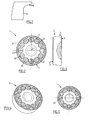
- Fig. 1 is a part of a railway wheel shown, the contour of which can be produced with required tolerances of a few tenths of a millimeter, by using a tool according to the invention can be produced.
- the rolled wheel blank is clamped and set about its axis of rotation in rotational movement, at the same time employed a tool carrying a cutting plate and thus a desired contour of the wheel is generated by turning.
- the region A which is currently formed and corresponds to the use of the wheel of a tread, worked with a feed rate of 1.5 mm / U and in the area B with a feed rate of 0.5 to 1.5 mm / U.
- a cutting insert 1 according to the invention with which a favorable chip breakage and avoidance of continuous or flow chips can be achieved with such a machining, is disclosed in US Pat Fig. 2 to Fig. 4 shown in more detail.
- an insert 1 according to the invention a top surface 2 and a parallel, opposite base 3 on.
- the top surface 2 and the base 3 are interconnected by a single free surface 4, which extends fully.
- the free surface 4 is inclined relative to the top surface 2 and the base 3 in order to set a suitable clearance angle.
- an open space area can also be subdivided into a plurality of sections which have a different inclination relative to the base area 3 or the top area 2.
- an outer circumference of the circular cutting plate 1 is determined by a cutting edge 5.
- a flat or sloping inclined formed region of about 0.4 mm width, which is followed by a sloping region 7 and immediately following this region 7, an ascending region 8, before the ascending region 8 merges into an area 9 formed parallel to the base surface 3.
- a plurality of recesses 71 and depressions are provided in the sloping region 7, which are set back in relation to the cutting edge 5 0.2 mm to 0.5 mm.
- the individual recesses 71 are arranged adjacent to each other and form a total of a circular, concentric with the cutting edge 5 extending row of elevations and depressions.
- the individual indentations 71 are each shaped so that they are tapered in their width b to the disk center. A length of the indentations corresponds essentially to that of the sloping region 7.
- curved portions 81 are provided, which are separated from each other.
- the bulges are shaped in such a way that a curvature of the sections 81 is provided both in the direction from the cutting edge 5 to the plate center 6 and in the direction of the circle formed by the sections 81.
- Each of the sections 81 which are spatially separated from each other, has a plurality of parallel ribs 82 directed toward the disc center or, in other words, elevations and depressions. These elevations and depressions, in cooperation with the indentations 71, cause a chip to undergo a multiple change of direction in a cutting insert, resulting in a desired formation of short chips.
- the indentations 71 are made larger in width b than their spacing between individual ribs 82.
- the ribs 82 or sections 81 do not only extend over the ascending region 8, but protrude upwards in the area 9 in order to offer the slipping chips as large an area as possible for forced changes in direction and thus to achieve a controlled chip breakage.
- an insert 1 according to the invention which can be produced, for example, from a laser-machined carbide blank, can also be designed so that the individual sections 81 are designed to merge into one another. Furthermore, it can be provided, as also from Fig. 5 It can be seen that the ribs 82 formed portions 81 are partially formed integrally with the recesses 71 are and already away from the sloping area 7 and extend into the flat area 9 inside.
Landscapes
- Engineering & Computer Science (AREA)
- Mechanical Engineering (AREA)
- Milling Processes (AREA)
- Cutting Tools, Boring Holders, And Turrets (AREA)
- Machines For Laying And Maintaining Railways (AREA)
- Processing Of Stones Or Stones Resemblance Materials (AREA)
Applications Claiming Priority (1)
| Application Number | Priority Date | Filing Date | Title |
|---|---|---|---|
| AT3042007A AT504993B1 (de) | 2007-02-27 | 2007-02-27 | Schneidplatte für radsatzbearbeitungswerkzeuge |
Publications (1)
| Publication Number | Publication Date |
|---|---|
| EP1964631A2 true EP1964631A2 (fr) | 2008-09-03 |
Family
ID=39512690
Family Applications (1)
| Application Number | Title | Priority Date | Filing Date |
|---|---|---|---|
| EP20080102011 Withdrawn EP1964631A2 (fr) | 2007-02-27 | 2008-02-26 | Plaque de coupe pour outils de traitement d'un ensemble de roues |
Country Status (5)
| Country | Link |
|---|---|
| EP (1) | EP1964631A2 (fr) |
| AT (1) | AT504993B1 (fr) |
| BR (1) | BRPI0800438A (fr) |
| RU (1) | RU2427452C2 (fr) |
| UA (1) | UA90158C2 (fr) |
Cited By (4)
| Publication number | Priority date | Publication date | Assignee | Title |
|---|---|---|---|---|
| EP2455172A1 (fr) * | 2010-11-19 | 2012-05-23 | SECO TOOLS AB (publ) | Insert de découpe avec cale évolutive ou angle de dégagement et porte-outil utilisant un tel insert de découpe |
| EP3366395A4 (fr) * | 2015-10-23 | 2019-06-12 | Sumitomo Electric Hardmetal Corp. | Outil de coupe rotatif |
| WO2020178152A1 (fr) * | 2019-03-07 | 2020-09-10 | Hartmetall-Werkzeugfabrik Paul Horn Gmbh | Plaquette de coupe et outil permettant d'usiner une pièce par enlèvement de copeaux |
| CN114603877A (zh) * | 2022-03-07 | 2022-06-10 | 普洱林达木业有限责任公司 | 一种环保型复合板生产工艺及其设备 |
Family Cites Families (3)
| Publication number | Priority date | Publication date | Assignee | Title |
|---|---|---|---|---|
| GB9520436D0 (en) * | 1995-10-06 | 1995-12-06 | Sandvik Ab | Cutting insert |
| RU2198767C2 (ru) * | 2000-12-29 | 2003-02-20 | Государственное научно-производственное предприятие "Технология" | Режущая пластина |
| RU30297U1 (ru) * | 2002-12-10 | 2003-06-27 | Закрытое акционерное общество "Дальневосточная технология" | Твердосплавная пластина металлорежущего инструмента |
-
2007
- 2007-02-27 AT AT3042007A patent/AT504993B1/de not_active IP Right Cessation
-
2008
- 2008-02-08 UA UAA200801623A patent/UA90158C2/ru unknown
- 2008-02-26 EP EP20080102011 patent/EP1964631A2/fr not_active Withdrawn
- 2008-02-27 RU RU2008107116/02A patent/RU2427452C2/ru not_active IP Right Cessation
- 2008-02-27 BR BRPI0800438 patent/BRPI0800438A/pt not_active IP Right Cessation
Cited By (10)
| Publication number | Priority date | Publication date | Assignee | Title |
|---|---|---|---|---|
| EP2455172A1 (fr) * | 2010-11-19 | 2012-05-23 | SECO TOOLS AB (publ) | Insert de découpe avec cale évolutive ou angle de dégagement et porte-outil utilisant un tel insert de découpe |
| WO2012065884A1 (fr) | 2010-11-19 | 2012-05-24 | Seco Tools Ab | Plaquette de coupe à angle de cale ou de dégagement évolutif et porte-outil utilisant une telle plaquette de coupe |
| CN103221165A (zh) * | 2010-11-19 | 2013-07-24 | 山高刀具公司 | 具有演变的楔角或余隙角的切削刀片和使用这种切削刀片的刀夹 |
| US9186733B2 (en) | 2010-11-19 | 2015-11-17 | Seco Tools Ab | Cutting insert with evolutive wedge or clearance angle and toolholder using such a cutting insert |
| CN103221165B (zh) * | 2010-11-19 | 2016-03-30 | 山高刀具公司 | 具有演变的楔角或余隙角的切削刀片和使用这种切削刀片的刀夹 |
| EP3366395A4 (fr) * | 2015-10-23 | 2019-06-12 | Sumitomo Electric Hardmetal Corp. | Outil de coupe rotatif |
| US10632541B2 (en) | 2015-10-23 | 2020-04-28 | Sumitomo Electric Hardmetal Corp. | Rotary cutting tool |
| WO2020178152A1 (fr) * | 2019-03-07 | 2020-09-10 | Hartmetall-Werkzeugfabrik Paul Horn Gmbh | Plaquette de coupe et outil permettant d'usiner une pièce par enlèvement de copeaux |
| CN114603877A (zh) * | 2022-03-07 | 2022-06-10 | 普洱林达木业有限责任公司 | 一种环保型复合板生产工艺及其设备 |
| CN114603877B (zh) * | 2022-03-07 | 2022-09-30 | 普洱林达木业有限责任公司 | 一种环保型复合板生产工艺及其设备 |
Also Published As
| Publication number | Publication date |
|---|---|
| RU2427452C2 (ru) | 2011-08-27 |
| AT504993A1 (de) | 2008-09-15 |
| UA90158C2 (ru) | 2010-04-12 |
| BRPI0800438A (pt) | 2008-10-14 |
| AT504993B1 (de) | 2009-09-15 |
| RU2008107116A (ru) | 2009-09-10 |
Similar Documents
| Publication | Publication Date | Title |
|---|---|---|
| EP1511590B1 (fr) | Fraise avec rayon de surfaçage | |
| DE2937585A1 (de) | Rotierendes schneidwerkzeug sowie rohling zu seiner herstellung | |
| EP0980297A1 (fr) | Plaquette de coupe pour usinage par enlevement de copeaux | |
| DD293975A5 (de) | Ringschneidwerkzeug und verfahren zu dessen herstellung | |
| DE2259108A1 (de) | Schneidelement fuer abspanende bearbeitung | |
| WO1999067046A1 (fr) | Plaquette de coupe, outil de coupe et procede d'usinage par enlevement de matiere, notamment de surfaces de pieces a symetrie de revolution | |
| EP3694670B1 (fr) | Outil de taillage en développante | |
| DE8325146U1 (de) | Spanbrecheinsatz für Metallschneidwerkzeuge | |
| EP2001622A1 (fr) | Insert de coupe et procédé d'usinage par enlèvement de copeaux de pièces entraînées en rotation | |
| EP3481575B1 (fr) | Outil de coupe de roues d'engrenages en forme de roue, procédé pour l'usinage de roues d'engrenages, procédé pour dresser ces outils de coupe et machine à usiner les roues d'engrenages | |
| EP0696942B1 (fr) | Plaquette de coupe polygonale | |
| EP2888066A1 (fr) | Foret à une lèvre | |
| DE01979299T1 (de) | Schneidwerkzeug, verfahren und vorrichtung zum herstellen desselben | |
| EP3287221B1 (fr) | Procédé de traitement de flancs de dents de pièces d'usinage d'accouplement plan selon un procédé de pièces individuelles semi-complètes | |
| AT504993B1 (de) | Schneidplatte für radsatzbearbeitungswerkzeuge | |
| DE102012212440B4 (de) | Bohrwerkzeug insbesondere zur Bearbeitung von Bauteilen aus einer Titanlegierung sowie Verfahren zur Bearbeitung eines solchen Bauteils | |
| EP2442937B1 (fr) | Procédé et dispositif d'outil pour profilage à la fraise | |
| DE10242109A1 (de) | Bearbeitungswerkzeug für Zahnräder und Verfahren zur Herstellung derselben | |
| EP2345497B1 (fr) | Procédé destiné à la fabrication d'une fraise mère développante | |
| EP2809469B1 (fr) | Plaquette de coupe | |
| DE8915215U1 (de) | Vorrichtung zum Herstellen von Profil-Werkstücken, insbesondere Zahnrädern | |
| DE102020103483A1 (de) | Vorrichtung und Verfahren zum Wälzschälen sowie dabei verwendbares Werkzeug | |
| DE2539881A1 (de) | Zahnaerztliches drehwerkzeug, insbesondere fraeser | |
| EP3804906B1 (fr) | Procédé de fabrication d'une géométrie de coupe coté extérieur dans un outil à tige de matériau plein destiné au traitement des matériaux | |
| DE2534574A1 (de) | Vorrichtung zum entgraten oder brechen der stirnkanten von zahnraedern |
Legal Events
| Date | Code | Title | Description |
|---|---|---|---|
| PUAI | Public reference made under article 153(3) epc to a published international application that has entered the european phase |
Free format text: ORIGINAL CODE: 0009012 |
|
| AK | Designated contracting states |
Kind code of ref document: A2 Designated state(s): AT BE BG CH CY CZ DE DK EE ES FI FR GB GR HR HU IE IS IT LI LT LU LV MC MT NL NO PL PT RO SE SI SK TR |
|
| AX | Request for extension of the european patent |
Extension state: AL BA MK RS |
|
| STAA | Information on the status of an ep patent application or granted ep patent |
Free format text: STATUS: THE APPLICATION IS DEEMED TO BE WITHDRAWN |
|
| 18D | Application deemed to be withdrawn |
Effective date: 20130903 |