EP1965586A2 - Appareil de capture d'image, système d'affichage d'image, et procédé de contrôle de l'appareil de capture d'image - Google Patents
Appareil de capture d'image, système d'affichage d'image, et procédé de contrôle de l'appareil de capture d'image Download PDFInfo
- Publication number
- EP1965586A2 EP1965586A2 EP08151971A EP08151971A EP1965586A2 EP 1965586 A2 EP1965586 A2 EP 1965586A2 EP 08151971 A EP08151971 A EP 08151971A EP 08151971 A EP08151971 A EP 08151971A EP 1965586 A2 EP1965586 A2 EP 1965586A2
- Authority
- EP
- European Patent Office
- Prior art keywords
- light
- image
- wavelength
- wavelength region
- intensity
- Prior art date
- Legal status (The legal status is an assumption and is not a legal conclusion. Google has not performed a legal analysis and makes no representation as to the accuracy of the status listed.)
- Granted
Links
- 238000000034 method Methods 0.000 title claims description 24
- 230000001186 cumulative effect Effects 0.000 claims description 11
- 230000007423 decrease Effects 0.000 claims description 11
- 230000001678 irradiating effect Effects 0.000 claims description 5
- 230000003287 optical effect Effects 0.000 description 15
- 238000004364 calculation method Methods 0.000 description 13
- 230000005855 radiation Effects 0.000 description 11
- 230000003247 decreasing effect Effects 0.000 description 6
- 230000008569 process Effects 0.000 description 3
- 230000008901 benefit Effects 0.000 description 2
- 238000006243 chemical reaction Methods 0.000 description 2
- 230000006870 function Effects 0.000 description 2
- 238000012986 modification Methods 0.000 description 2
- 230000004048 modification Effects 0.000 description 2
- 230000004044 response Effects 0.000 description 2
- 230000005540 biological transmission Effects 0.000 description 1
- 230000008859 change Effects 0.000 description 1
- 238000010586 diagram Methods 0.000 description 1
- 239000011159 matrix material Substances 0.000 description 1
- QSHDDOUJBYECFT-UHFFFAOYSA-N mercury Chemical compound [Hg] QSHDDOUJBYECFT-UHFFFAOYSA-N 0.000 description 1
- 229910052753 mercury Inorganic materials 0.000 description 1
- 230000001629 suppression Effects 0.000 description 1
- 230000001131 transforming effect Effects 0.000 description 1
Images

Classifications
-
- H—ELECTRICITY
- H04—ELECTRIC COMMUNICATION TECHNIQUE
- H04N—PICTORIAL COMMUNICATION, e.g. TELEVISION
- H04N23/00—Cameras or camera modules comprising electronic image sensors; Control thereof
- H04N23/70—Circuitry for compensating brightness variation in the scene
- H04N23/74—Circuitry for compensating brightness variation in the scene by influencing the scene brightness using illuminating means
-
- G—PHYSICS
- G03—PHOTOGRAPHY; CINEMATOGRAPHY; ANALOGOUS TECHNIQUES USING WAVES OTHER THAN OPTICAL WAVES; ELECTROGRAPHY; HOLOGRAPHY
- G03B—APPARATUS OR ARRANGEMENTS FOR TAKING PHOTOGRAPHS OR FOR PROJECTING OR VIEWING THEM; APPARATUS OR ARRANGEMENTS EMPLOYING ANALOGOUS TECHNIQUES USING WAVES OTHER THAN OPTICAL WAVES; ACCESSORIES THEREFOR
- G03B15/00—Special procedures for taking photographs; Apparatus therefor
- G03B15/02—Illuminating scene
- G03B15/03—Combinations of cameras with lighting apparatus; Flash units
- G03B15/05—Combinations of cameras with electronic flash apparatus; Electronic flash units
-
- H—ELECTRICITY
- H04—ELECTRIC COMMUNICATION TECHNIQUE
- H04N—PICTORIAL COMMUNICATION, e.g. TELEVISION
- H04N23/00—Cameras or camera modules comprising electronic image sensors; Control thereof
- H04N23/56—Cameras or camera modules comprising electronic image sensors; Control thereof provided with illuminating means
-
- G—PHYSICS
- G03—PHOTOGRAPHY; CINEMATOGRAPHY; ANALOGOUS TECHNIQUES USING WAVES OTHER THAN OPTICAL WAVES; ELECTROGRAPHY; HOLOGRAPHY
- G03B—APPARATUS OR ARRANGEMENTS FOR TAKING PHOTOGRAPHS OR FOR PROJECTING OR VIEWING THEM; APPARATUS OR ARRANGEMENTS EMPLOYING ANALOGOUS TECHNIQUES USING WAVES OTHER THAN OPTICAL WAVES; ACCESSORIES THEREFOR
- G03B2215/00—Special procedures for taking photographs; Apparatus therefor
- G03B2215/05—Combinations of cameras with electronic flash units
-
- H—ELECTRICITY
- H04—ELECTRIC COMMUNICATION TECHNIQUE
- H04N—PICTORIAL COMMUNICATION, e.g. TELEVISION
- H04N23/00—Cameras or camera modules comprising electronic image sensors; Control thereof
- H04N23/20—Cameras or camera modules comprising electronic image sensors; Control thereof for generating image signals from infrared radiation only
- H04N23/21—Cameras or camera modules comprising electronic image sensors; Control thereof for generating image signals from infrared radiation only from near infrared [NIR] radiation
Definitions
- the invention generally relates to an image pickup apparatus and image display system for picking up infrared images, and to a method for controlling the image pickup apparatus. Aspects of the invention relate to an apparatus, to a system, to a method and to a vehicle.
- an image pickup apparatus that picks up images of an object by radiating infrared radiation to the object and capturing light reflected by the object has been known from, for example, Japanese Unexamined Patent Application Publication No. 2-304680 .
- Such an image pickup apparatus can determine a difference between an image obtained when infrared radiation is not radiated and an image obtained when infrared radiation is radiated.
- infrared radiation When infrared radiation is not radiated, external light impinges on the object and is reflected by the object.
- light picked up by the image pickup apparatus is only an external light component.
- infrared radiation when infrared radiation is radiated, external light and infrared radiation impinge on the object and are reflected by the object.
- the light picked up by the image pickup apparatus includes an external light component and an infrared component.
- the difference between the image obtained when infrared radiation is not radiated and the image obtained when infrared radiation is radiated is an image in which the external light component is canceled and only the infrared component is extracted. Accordingly, this image pickup apparatus can obtain an image in which the influence of external light is suppressed.
- the apparatus radiates infrared radiation having a predetermined wavelength component.
- the amount of suppression of external light is small. Accordingly, even if the image difference is determined as described, a clear image is difficult to obtain.
- Embodiments of the invention may provide an apparatus, a system and a method which can pick up a clear image in accordance with a state of external light. Other aims and advantages of the invention will become apparent from the following description, claims and drawings.
- an image pickup apparatus comprising an irradiation unit configured to radiate light having a plurality of wavelength regions to an object, an image pickup unit configured to pick up a first image of the object obtained in a presence of the radiated light and a second image of the object in an absence of the radiated light, a wavelength region calculating unit configured to determine a wavelength region among the plurality of wavelength regions in which intensity of external light is low based on the first image and the second image and an irradiation control unit configured to control the radiated light from the irradiation unit to increase an emission intensity of light having the wavelength region determined by the wavelength region calculating unit.
- the irradiation control unit is configured to control the radiated light from the irradiation unit to increase the emission intensity of light having the wavelength region determined by the wavelength region calculating unit to a value higher than emission intensities of light having the remaining plurality of wavelength regions.
- the wavelength region calculating unit is configured to determine difference values between the first image and the second image for individual wavelength regions of the plurality of wavelength regions and conclude that a wavelength region having the largest difference value among the difference values for the individual wavelength regions is the wavelength region among the plurality of wavelength regions in which the intensity of the external light is low.
- the wavelength region calculating unit is configured to determine difference values between the first image and the second image for individual wavelength regions of the plurality of wavelength regions a plural number of times and obtain cumulative values of the difference values separately for the individual wavelength regions; and wherein the wavelength region calculating unit is configured to determine the wavelength region among the plurality of wavelength regions in which intensity of external light is low based on the first image and the second image by using the cumulative values.
- the irradiation control unit is configured to maintain a sum of emission intensities of the radiated light as a constant and control the radiated light from the irradiation unit to increase the emission intensity of light having the wavelength region determined by the wavelength region calculating unit and decrease emission intensities of light having the remaining plurality of wavelength regions.
- the irradiation control unit is configured to maintain the emission intensities of light having the remaining plurality of wavelength regions at values greater than zero.
- the wavelength region calculating unit is configured to determine the wavelength region among the plurality of wavelength regions as a wavelength region in which the intensity of the external light is lowest.
- an image pickup apparatus comprising means for radiating light having a plurality of wavelength regions to an object, means for picking up a first image of the object obtained in a presence of the radiated light and a second image of the object in an absence of the radiated light, means for determining a wavelength region among the plurality of wavelength regions in which intensity of external light is low based on the first image and the second image and means for controlling the radiating light means to increase an emission intensity of light having the wavelength region determined by the determining means.
- an image display system comprising an image pickup apparatus, including an irradiation unit configured to radiate light having a plurality of wavelength regions to an object, an image pickup unit configured to pick up a first image of the object obtained in a presence of the radiated light and a second image of the object in an absence of the radiated light, a wavelength region calculating unit configured to determine a wavelength region among the plurality of wavelength regions in which intensity of external light is low based on the first image and the second image and an irradiation control unit configured to control the radiated light from the irradiation unit to increase an emission intensity of light having the wavelength region determined by the wavelength region calculating unit and a display unit configured to display an image based on difference image data representing a difference between the first image and the second image.
- an image pickup apparatus including an irradiation unit configured to radiate light having a plurality of wavelength regions to an object, an image pickup unit configured to pick up a first image of the object obtained in a presence of the radiated light and a second image
- a control method for an image pickup apparatus comprising picking up a first image of an object when radiated light having a plurality of wavelength regions is irradiated to the object, picking up a second image of the object in an absence of the radiated light, determining a wavelength region among the plurality of wavelength regions in which intensity of external light is low based on the first image and the second image and irradiating the radiated light in a state in which an emission intensity of light having the determined wavelength region is increased.
- the method may comprise controlling the radiated light to increase the emission intensity of light having the determined wavelength region to a value higher than emission intensities of light having the remaining plurality of wavelength regions.
- the method may comprise calculating difference values between the first image and the second image for individual wavelength regions of the plurality of wavelength regions and concluding that a wavelength region having the largest difference value among the difference values for the individual wavelength regions is the wavelength region among the plurality of wavelength regions in which the intensity of the external light is low.
- the method may comprise calculating difference values between the first image and the second image for individual wavelength regions of the plurality of wavelength regions a plural number of times and obtaining cumulative values of the difference values separately for the individual wavelength regions; and wherein determining a wavelength region among the plurality of wavelength regions in which intensity of external light is low based on the first image and the second image includes determining the wavelength region among the plurality of wavelength regions in which intensity of external light is low using the cumulative values.
- the method may comprise maintaining a sum of emission intensities of the radiated light as a constant and wherein irradiating the radiated light in the state in which an emission intensity of light having the determined wavelength region is increased includes increasing the emission intensity of light having the determined wavelength region and decreasing emission intensities of light having the remaining plurality of wavelength regions.
- the method may comprise maintaining the emission intensities of light having the remaining plurality of wavelength regions at values greater than zero while decreasing the emission intensities of light having the remaining plurality of wavelength regions.
- the method may comprise displaying an image based on difference image data representing a difference between the first image and the second image.
- the method comprises calculating difference values between the first image and the second image for individual wavelength regions of the plurality of wavelength regions and concluding that a wavelength region having the largest difference value among the difference values for the individual wavelength regions is the wavelength region among the plurality of wavelength regions in which the intensity of the external light is low.
- the method comprises maintaining a sum of emission intensities of the radiated light as a constant; and wherein irradiating the radiated light in the state in which an emission intensity of light having the determined wavelength region is increased includes increasing the emission intensity of light having the determined wavelength region and decreasing emission intensities of light having the remaining plurality of wavelength regions.
- the method may comprise maintaining the emission intensities of light having the remaining plurality of wavelength regions at values greater than zero while decreasing the emission intensities of light having the remaining plurality of wavelength regions.
- the method comprises calculating difference values between the first image and the second image for individual wavelength regions of the plurality of wavelength regions a plural number of times and obtaining cumulative values of the difference values separately for the individual wavelength regions; and wherein determining a wavelength region among the plurality of wavelength regions in which intensity of external light is low based on the first image and the second image includes determining the wavelength region among the plurality of wavelength regions in which intensity of external light is low using the cumulative values.
- a method may comprise picking up a first image of an object when radiated light having a plurality of wavelength regions is irradiated to the object, picking up a second image of the object in an absence of the radiated light, determining a wavelength region among the plurality of wavelength regions in which intensity of external light is low based on the first image and the second image and irradiating the radiated light in a state in which an emission intensity of light having the determined wavelength region is increased.
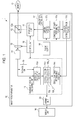
- the image display system 1 includes the image pickup apparatus 10 and a display unit 30.
- the image display system 1 displays, on the display unit 30, an image picked up by the image pickup apparatus 10 that includes the object O.
- an image picked up by the image pickup apparatus 10 is displayed on the display unit 30 in this embodiment, display of the image on the display unit 30 is not required.
- the image picked up by the image pickup apparatus 10 may be used for processing such as image processing to detect the position of the object O.
- the image pickup apparatus 10 includes an irradiation unit 11, an optical splitter 12, an optical filter 13, a camera 14, a storage unit 15, a wavelength region calculating unit 16, an irradiation control unit 17, a power supply 18, a control unit 19 and an adding unit 20.
- the wavelength region calculating unit 16, the irradiation control unit 17, the control unit 19 and the adding unit 20 can be implemented by, for example, one or more microcomputers including a random access memory (RAM), a read-only memory (ROM), a central processing unit (CPU), etc., in addition to various input and output connections.
- RAM random access memory
- ROM read-only memory
- CPU central processing unit
- the functions described herein for these units and their respective portions are performed by execution of one or more software programs stored in ROM by the CPU.
- some or all of the functions described for the units could alternatively be performed in whole or in part by hardware components.
- the irradiation unit 11 includes, for example, light-emitting diodes, and radiates light having a plurality of wavelength regions to a predetermined irradiation range.
- FIGS. 2A and 2B are detailed illustrations of the irradiation unit 11.
- the irradiation unit 11 has an emission portion 11 a, a lens 11 b, and a housing 11c.
- the emission portion 11 a is an LED (light emitting diode) unit in which light-emitting regions corresponding to light-emitting elements are arranged in a matrix having ten vertical regions by ten horizontal regions. Each light-emitting region can radiate light having a plurality of predetermined wavelength regions.
- each light-emitting element can radiate light having three wavelength regions in a wavelength (near infrared) range of 700 to 1000 nm.
- center wavelengths in the near infrared region are represented by, for example, ⁇ 1, ⁇ 2, and ⁇ 3, the light-emitting element can radiate light having wavelength width ⁇ around each center wavelength.
- the light-emitting element can time-divisionally output radiated light having center wavelength ⁇ 1, radiated light having center wavelength ⁇ 2 and radiated light having center wavelength ⁇ 3.
- the light radiated by the light-emitting element passes through the lens 11 b, which is fixed to the housing 11c, and is input to the optical splitter 12.
- the optical splitter 12 has therein a half mirror 12a.
- the half mirror 12a reflects the light from the irradiation unit 11. Reflection by the half mirror 12a is directed to the object O. Reflected light (including both light in which the radiated light from the image pickup apparatus 10 is reflected and light in which the external light is reflected) from the object O is incident on the optical splitter 12. The reflected light passes through the half mirror 12a and is input to the optical filter 13.
- the optical filter 13 is a filter that can select a wavelength to be transmitted. A transmission wavelength can be changed based on the control of the control unit 19. Here, the optical filter 13 is controlled to only transmit the light having the wavelength regions radiated by the irradiation unit 11.
- the camera 14 By receiving the reflected light from the object O and photoelectrically converting the light, the camera 14 obtains picked-up-image data including an image of the object O. In addition, based on time-divisional control, the irradiation unit 11 switches between a state in which the irradiation unit 11 radiates light and a state in which the irradiation unit 11 does not radiate light. Accordingly, when light having wavelength regions is radiated by the irradiation unit 11, the camera 14 obtains picked-up-image data (irradiation-mode picked-up-image data) by receiving reflected light including light in which the external light is reflected by the object O and light in which the radiated light is reflected by the object O.
- picked-up-image data irradiation-mode picked-up-image data
- the camera 14 obtains picked-up-image data (non-irradiation-mode picked-up-image data) by receiving reflected light including only light in which the external light is reflected by the object O.
- the storage unit 15 stores the irradiation-mode picked-up-image data obtained by the camera 14.
- the storage unit 15 may store only the non-irradiation-mode picked-up-image data obtained when the light is not radiated by the irradiation unit 11, or both the irradiation-mode picked-up-image data and the non-irradiation-mode picked-up-image data.
- the storage unit 15 could be stand-alone memory as shown or could be integrated memory of the one or more microcomputers of the image pickup apparatus 10 or the camera 14 described above
- the wavelength region calculating unit 16 determines, among the wavelength regions, a wavelength in which the intensity of the external light is lowest.
- the wavelength region calculating unit 16 includes a difference calculating portion 16a, a storage portion 16b and a calculation portion 16c.
- the difference calculating portion 16a determines a difference between the irradiation-mode picked-up-image data and the non-irradiation-mode picked-up-image data for each of the wavelength regions. More specifically, the difference calculating portion 16a determines a difference value (that is, a first difference value) between first irradiation-mode picked-up-image data obtained when light having center wavelength ⁇ 1 is radiated and the non-irradiation-mode picked-up-image data obtained when the light is not radiated.
- a difference value that is, a first difference value
- the difference calculating portion 16a determines a difference value (that is, a second difference value) between second irradiation-mode picked-up-image data obtained when light having center wavelength ⁇ 2 is radiated and the non-irradiation-mode picked-up-image data, and determines a difference value (that is, a third difference value) between third irradiation-mode picked-up-image data obtained when light having center wavelength ⁇ 3 is irradiated and the non-irradiation-mode picked-up-image data.
- a difference value that is, a second difference value
- a difference value that is, a third difference value
- the storage portion 16b separately stores the first to third difference values determined by the difference calculating portion 16a.
- the storage portion 16b has an internal configuration in which the storage portion 16b is logically or physically divided into a first-difference-value storage area 16b_1, a second-difference-value storage area 16b_2, and a third-difference-value storage area 16b_3.
- the storage portion 16b has a storage capacity capable of storing each difference value m times.
- the storage portion 16b includes an image memory for storing difference values (i.e., difference images) for m images having numbers 1 to m assigned in a time-series manner.
- the storage portion 16b Whenever a new difference value is determined, in the storage portion 16b the above number is incremented by "1" and the new difference value is stored in the image memory. After the number reaches the predetermined value m, when a new difference value is determined the number returns to "1". In addition, the storage portion 16b outputs the sum (i.e., a total difference value) of m difference values to the calculation portion 16c.
- the calculation portion 16c determines, among the wavelength regions, a wavelength region in which the intensity of the external light is lowest.
- a calculation method by the calculation portion 16c is described.
- a reflectance of the object O at specified wavelength ⁇ is represented by R( ⁇ )
- the intensity of the external light at specified wavelength ⁇ is represented by Pe( ⁇ )
- the intensity of the radiated light at specified wavelength ⁇ is represented by Ps( ⁇ )
- a total of wavelength characteristics of optical components included in the optical splitter 12 the optical filter 13 and the camera 14 and a wavelength characteristic in an image pickup mode is represented by ⁇ ( ⁇ )
- first difference value Is( ⁇ 1) is represented by log(1+Ps( ⁇ 1))/Pe( ⁇ 1)
- second difference value Is( ⁇ 2) is represented by log(1+Ps( ⁇ 2))/Pe( ⁇ 2)
- third difference value Is( ⁇ 3) is represented by log(1+Ps( ⁇ 3))/Pe( ⁇ 3)).
- a wavelength region in which the difference value Is is largest can be specified as a wavelength region in which the intensity of the external light is lowest.
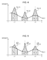
- the intensity of light radiated to the object O has a distribution for each wavelength as shown in FIG. 4 .
- Pe( ⁇ 1), Pe( ⁇ 2) and Pe( ⁇ 3) each representing a denominator in the logarithm in equation (3)
- Ps( ⁇ 1), Ps( ⁇ 2) and Ps( ⁇ 3) each representing a numerator in the logarithm in equation (3)
- the calculation portion 16c specifies this wavelength region as a wavelength region in which the intensity of the external light is lowest.
- the storage portion 16b stores the difference values.
- Is( ⁇ ) does not have any negative value. Accordingly, by storing the difference values in the storage portion 16b, the wavelength region calculating unit 16 can set a difference between wavelengths to be large. Therefore, the wavelength region calculating unit 16 can more accurately specify a wavelength region in which the intensity of the external light is low.
- the irradiation control unit 17 increases the emission intensity of light having the wavelength region determined by the wavelength region calculating unit 16 in the light having wavelength regions, and controls the irradiation unit 11 to radiate the light having the wavelength regions.
- the power supply 18 supplies a driving current to the image pickup apparatus 10. Under the control of the irradiation control unit 17, the driving current from the power supply 18 is supplied to each light-emitting element in the irradiation unit 11.
- the irradiation control unit 17 includes an emission intensity determining portion 17a, an emission intensity storage portion 17b, and a current control portion 17c.
- the emission intensity determining portion 17a determines the intensity of emission when the irradiation unit 11 radiates light having wavelength regions.
- the emission intensity determining portion 17a determines the intensity of emission in four levels from “0" to "3", in which "0” represents OFF, "1” represents a small intensity of emission, “2” represents an intermediate intensity of emission, and "3” represents a large intensity of emission.
- the emission intensity determining portion 17a determines a high intensity of emission for light having the wavelength region determined by the wavelength region calculating unit 16.
- the emission intensity determining portion 17a determines that the emission intensity of ⁇ 1 is "3" and determines that the emission intensities of ⁇ 2 and ⁇ 3 are "1".
- the emission intensity storage portion 17b stores an emission intensity of light, having each wavelength, radiated from the irradiation unit 11. Whenever the emission intensity determining portion 17a determines an emission intensity, emission intensity information is input and stored in the emission intensity storage portion 17b.
- the current control portion 17c controls the irradiation unit 11 based on the emission intensity determined by the emission intensity determining portion 17a.
- the current control portion 17c increases the emission intensity of light having the wavelength region determined by the emission intensity determining portion 17a and controls the irradiation unit 11 to radiate the light.
- the current control portion 17c maintains the emission intensity of irradiation from the irradiation unit 11 to be constant. Accordingly, even in a case in which only the emission intensity of some wavelength region is increased, unnecessary power is not consumed for an increase in emission intensity.
- FIG. 5 is a graph showing the intensity Pe( ⁇ ) of the external light at each wavelength and the intensity ⁇ n ⁇ Ps( ⁇ ) of the radiated light at each wavelength region.
- FIG. 5 shows a state obtained after the emission intensity of light radiated from the irradiation unit 11 is changed according to the intensity of the external light.
- the emission intensity determining portion 17a determines that an emission intensity of a wavelength region centered on ⁇ 2 is increased and determines that emission intensities of wavelength regions centered on ⁇ 1 and ⁇ 3 are decreased
- the irradiation-intensity-to-wavelength characteristic shown in FIG. 4 changes to that shown in FIG. 5 .
- the irradiation intensity of the wavelength region around ⁇ 2 is multiplied by ⁇ 2, so that ⁇ 2 ⁇ Ps( ⁇ 2)/Pe( ⁇ 2). This value increases so as to be higher than Ps( ⁇ 2)/Pe( ⁇ 2), and second difference value Is( ⁇ 2) increases. This makes it possible to perform efficient image pickup.
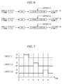
- the current control portion 17c controls irradiation of the irradiation unit 11 as shown in FIGS. 6 and 7 .
- the current control portion 17c receives emission-intensity information V( ⁇ ) determined by the emission intensity determining portion 17a and changes the emission-intensity information V( ⁇ ) into a voltage by performing digital-to-analog conversion on the emission-intensity information V( ⁇ ).
- the current control portion 17c supplies each light-emitting element with a current ( ⁇ ) according to the emission-intensity information V( ⁇ ) by using the voltage obtained in the digital-to-analog conversion to control a transistor or the like. At this time, the current control portion 17c supplies the light-emitting element with the current from the power supply 18.
- the current control portion 17c supplies a current ( ⁇ ) to the irradiation unit 11 in units of wavelengths of irradiation from the irradiation unit 11 by performing time-division control. Specifically, from time 0 to time T1, the current control portion 17c does not supply any current. This allows the camera 14 to obtain non-irradiation-mode picked-up-image data when no irradiation is performed by the irradiation unit 11. Next, from time T1 to time T2, the current control portion 17c supplies the current ( ⁇ 1). This allows the camera 14 to obtain irradiation-mode picked-up-image data when light having a wavelength region having center wavelength ⁇ 1 is radiated by the irradiation unit 11.
- the current control portion 17c does not supply any current. This allows the camera 14 to obtain non-irradiation-mode picked-up-image data when no irradiation is performed by the irradiation unit 11.
- the current control portion 17c supplies a current ( ⁇ 2). This allows the camera 14 to obtain irradiation-mode picked-up-image data when light having a wavelength region having center wavelength ⁇ 2 is radiated by the irradiation unit 11.
- the current control portion 17c does not supply any current. This allows the camera 14 to obtain non-irradiation-mode picked-up-image data when no irradiation is performed by the irradiation unit 11.
- the current control portion 17c supplies a current ( ⁇ 3). This allows the camera 14 to obtain irradiation-mode picked-up-image data when light having a wavelength region having center wavelength ⁇ 3 is radiated by the irradiation unit 11. Subsequently, the current control portion 17c time-divisionally supplies the current ( ⁇ ) in the same manner.
- the control unit 19 controls the entirety of the image pickup apparatus 10 and establishes synchronization of each unit.
- the adding unit 20 forms a difference image by adding the first difference value ( ⁇ 1), second difference value ( ⁇ 2) and third difference value ( ⁇ 3) stored in the storage portion 16b and outputs the difference image to the display unit 30.
- the display unit 30 receives data of the difference image from the image pickup apparatus 10 and displays an image.
- the calculation portion 16c determines a wavelength region in which the intensity of the external light is lowest based on the difference value. In addition to that, the calculation portion 16c determines a wavelength region in which the intensity of the external light is lowest based on information stored in the current control portion 17c. In the description of equation (3), ⁇ n is not considered. When the current control portion 17c increases an emission intensity of some wavelength region, as is clear from FIG. 5 , the value of difference value Is for the wavelength region is large. Thus, if the first to third difference values are simply compared, a problem may occur when specifying a wavelength region in which the intensity of the external light is lowest.
- the calculation portion 16c determines a wavelength region in which the intensity of the external light is lowest. In this manner, a wavelength region in which the intensity of the external light is lowest is more accurately determined.
- the external light intensities in the wavelength regions can be determined by equations (6) to (8).
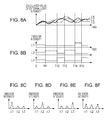
- FIG. 8A shows external light intensities determined by the calculation portion 16c.
- FIG. 8B shows emission intensities determined by the emission intensity determining portion 17a in a time-change manner.
- FIGS. 8C to 8F separately show emission intensities determined by the emission intensity determining portion 17a.
- the emission intensity determining portion 17a increases the intensity of light having wavelength component ⁇ 3 (emission intensity "3": large) and decreases intensities of light having other wavelength components ⁇ 1 and ⁇ 2 (emission intensity "1": small).
- the irradiation unit 11 time-divisionally radiates the light at the above intensities.
- the emission intensity determining portion 17a increases an intensity of wavelength component ⁇ 2 (emission intensity "3": large) and decreases intensities of light having other wavelength components ⁇ 1 and ⁇ 3 (emission intensity "1": small).
- the irradiation unit 11 time-divisionally radiates the light at the above intensities.
- the emission intensity determining portion 17a increases the intensity of external light having wavelength component ⁇ 1 (emission intensity "3": large) and decreases intensities of light having other wavelength components ⁇ 2 and ⁇ 3 (emission intensity "1": small).
- the irradiation unit 11 time-divisionally radiates the light at the above intensities.
- the emission intensity determining portion 17a increases the intensity of light having wavelength component ⁇ 3 (emission intensity "3": large) and decreases the intensities of light having other wavelength components ⁇ 1 and ⁇ 2 (emission intensity "1": small). Subsequently, the image display system 1 repeatedly executes the above-described processing.
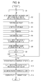
- step S1 the image pickup apparatus 10 sets a number representing a wavelength region n to "1."
- step S2 the irradiation control unit 17 controls the irradiation unit 11 to radiate, at a determined intensity, light having a wavelength region having center wavelength ⁇ n.
- step S3 the camera 14 picks up an image of an area including the object O. This allows the image pickup apparatus 10 to obtain an image when light having a wavelength region with center wavelength ⁇ n is radiated.
- step S4 the storage unit 15 stores the image picked up by the camera 14.
- step S5 the irradiation control unit 17 stops irradiation of the irradiation unit 11.
- step S6 the camera 14 picks up an image of an area including the object O. This allows the image pickup apparatus 10 to obtain non-irradiation-mode picked-up-image data.
- step S7 the difference calculating portion 16a calculates a difference value at center wavelength ⁇ n.
- step S8 the storage portion 16b stores the difference value at center wavelength ⁇ n.
- step S9 number n, which represents the wavelength region, is incremented by the image pickup apparatus 10.
- step S10 it is determined whether or not number n representing the wavelength region is "3", in this example. If n is not "3" (response is "NO” in step S10), the process returns to step S2.
- step S11 the calculation portion 16c reads, from the current control portion 17c, information on the emission intensity of the light radiated in step S2.
- step S12 the calculation portion 16c calculates an external light intensity in each wavelength region.
- step S13 the emission intensity determining portion 17a determines the emission intensity of the radiated light in each wavelength region based on the external light intensity determined in step S12.
- step S14 the emission intensity storage portion 17b stores information of the emission intensity determined in step S13.
- the process shown in FIG. 9 then ends.
- the process shown in FIG. 9 is repeatedly executed until the power supply of the image display system 1 is turned off.
- the image display system 1 and the image pickup method of this embodiment As described above, according to the image pickup apparatus 10, the image display system 1 and the image pickup method of this embodiment, a wavelength region in which the intensity of external light is lowest is determined, and an emission intensity of light having the determined wavelength region is increased from an image obtained when light having wavelength regions is radiated and an image obtained when the light is not radiated. Therefore, light having a wavelength region in which the intensity of the external light is low, that is, light having a wavelength region that is hardly affected by the external light, can be radiated from the irradiation unit 11. This makes it possible to perform image pickup in accordance with the intensity of the external light.
- differences between an image obtained when light having each wavelength region is radiated and an image obtained when the light is not radiated are determined for a plurality of wavelength regions.
- a wavelength region that has the largest difference value among difference values for the wavelength regions is determined as a wavelength region in which the intensity of the external light is lowest.
- the difference values tend to decrease as the intensity of the external light increases. Accordingly, in the above manner, a wavelength region in which the intensity of the external light is lowest can be determined.
- the difference values are determined for the individual wavelength regions a plural number of times, and cumulative values of the difference values are obtained separately for the individual wavelength regions. From the cumulative values, a wavelength region in which the intensity of the external light is lowest is determined. Here, the difference values do not become negative values. Thus, the cumulative values increase. This makes it possible to remarkably represent a difference, so that a wavelength region in which the external light is lowest can be accurately determined.
- light having a wavelength region that is not determined by the wavelength region calculating unit 16 is decreased without setting its emission intensity to "0". If the intensity of light having a specified wavelength region is set to "0", a difference value for the wavelength region cannot be determined, so that further determination of wavelength regions of radiated light is affected. However, in the above-described manner, efficient image pickup can be continued in accordance with the intensity of the external light without affecting further determination of wavelength regions of radiated light.
- an optical axis of the camera 14 match an optical axis of light radiated from the irradiation unit 11, and it is preferable that an emission intensity of only each light-emitting element whose light reaches the object O be changed.
- Matching of the optical axes establishes matching between an x-y position of the light-emitting element and an x-y position of a picked-up image. Accordingly, the light-emitting element whose light reaches the object O can be specified. By changing the emission intensity of only the light-emitting element whose light reaches the object O, an image of the object O can be efficiently picked up without changing emission intensities of other light-emitting elements.
- the radiated light is near-infrared radiation
- the invention is not limited to near-infrared radiation.
- light having a wavelength region whose intensity is small may be radiated. This makes it possible to perform efficient image pickup during daytime hours.
- light of a mercury lamp and fluorescent light light having a wavelength region whose intensity is small may be radiated. This makes it possible to perform efficient image pickup during night-time hours.
- light having each wavelength region is time-divisionally radiated.
- image pickup may also be performed. This produces an advantage similar to that obtained when light having each wavelength region is time-divisionally radiated.
Landscapes
- Engineering & Computer Science (AREA)
- Multimedia (AREA)
- Signal Processing (AREA)
- Physics & Mathematics (AREA)
- General Physics & Mathematics (AREA)
- Studio Devices (AREA)
- Stroboscope Apparatuses (AREA)
Applications Claiming Priority (1)
| Application Number | Priority Date | Filing Date | Title |
|---|---|---|---|
| JP2007052948A JP4407707B2 (ja) | 2007-03-02 | 2007-03-02 | 撮像装置、画像表示システム、撮像装置の制御方法 |
Publications (3)
| Publication Number | Publication Date |
|---|---|
| EP1965586A2 true EP1965586A2 (fr) | 2008-09-03 |
| EP1965586A3 EP1965586A3 (fr) | 2008-12-17 |
| EP1965586B1 EP1965586B1 (fr) | 2010-12-22 |
Family
ID=39431045
Family Applications (1)
| Application Number | Title | Priority Date | Filing Date |
|---|---|---|---|
| EP08151971A Ceased EP1965586B1 (fr) | 2007-03-02 | 2008-02-27 | Appareil de capture d'image, système d'affichage d'image, et procédé de contrôle de l'appareil de capture d'image |
Country Status (5)
| Country | Link |
|---|---|
| US (1) | US7659511B2 (fr) |
| EP (1) | EP1965586B1 (fr) |
| JP (1) | JP4407707B2 (fr) |
| CN (1) | CN101257574B (fr) |
| DE (1) | DE602008003990D1 (fr) |
Cited By (1)
| Publication number | Priority date | Publication date | Assignee | Title |
|---|---|---|---|---|
| EP2667588A3 (fr) * | 2012-05-22 | 2013-12-11 | Fujitsu General Limited | Appareil de capture d'image de vision nocturne et appareil à rayonnement infrarouge et système de capture d'image de vision nocturne |
Families Citing this family (2)
| Publication number | Priority date | Publication date | Assignee | Title |
|---|---|---|---|---|
| JP2011199798A (ja) * | 2010-03-24 | 2011-10-06 | Sony Corp | 物理情報取得装置、固体撮像装置、物理情報取得方法 |
| JP2017212512A (ja) * | 2016-05-24 | 2017-11-30 | 三星ダイヤモンド工業株式会社 | 撮像装置および画像管理システム |
Citations (2)
| Publication number | Priority date | Publication date | Assignee | Title |
|---|---|---|---|---|
| JPH02304680A (ja) | 1989-05-19 | 1990-12-18 | Toshiba Corp | 画像処理装置 |
| JP2007052948A (ja) | 2005-08-16 | 2007-03-01 | Toyota Motor Corp | 燃料電池システム |
Family Cites Families (9)
| Publication number | Priority date | Publication date | Assignee | Title |
|---|---|---|---|---|
| JPS6055924A (ja) | 1983-09-05 | 1985-04-01 | オリンパス光学工業株式会社 | 内視鏡の撮像用自動調光装置 |
| DE3335509C2 (de) * | 1983-09-30 | 1986-05-07 | Karl Schaeff GmbH & Co, 7183 Langenburg | Gesteinsbrecher-Räumwerkzeug-Kombination für eine Arbeitsmaschine |
| GB2223844A (en) * | 1988-10-12 | 1990-04-18 | Graviner Ltd | Flame detector |
| US5677532A (en) * | 1996-04-22 | 1997-10-14 | Duncan Technologies, Inc. | Spectral imaging method and apparatus |
| US6648506B2 (en) * | 2001-09-07 | 2003-11-18 | Board Of Trustees Of Michigan State University | Fluorescence emission ratio imaging thermography for use in heat transfer analysis |
| US6871409B2 (en) * | 2002-12-18 | 2005-03-29 | Snap-On Incorporated | Gradient calculating camera board |
| US7319805B2 (en) * | 2003-10-06 | 2008-01-15 | Ford Motor Company | Active night vision image intensity balancing system |
| TWI302756B (en) * | 2004-04-19 | 2008-11-01 | Phoseon Technology Inc | Imaging semiconductor structures using solid state illumination |
| KR20060075327A (ko) * | 2004-12-28 | 2006-07-04 | 현대자동차주식회사 | 적외선 파장 가변형 active nightvision 시스템 및 그 방법 |
-
2007
- 2007-03-02 JP JP2007052948A patent/JP4407707B2/ja not_active Expired - Fee Related
-
2008
- 2008-01-26 US US12/020,525 patent/US7659511B2/en active Active
- 2008-02-27 CN CN200810080967XA patent/CN101257574B/zh not_active Expired - Fee Related
- 2008-02-27 EP EP08151971A patent/EP1965586B1/fr not_active Ceased
- 2008-02-27 DE DE602008003990T patent/DE602008003990D1/de active Active
Patent Citations (2)
| Publication number | Priority date | Publication date | Assignee | Title |
|---|---|---|---|---|
| JPH02304680A (ja) | 1989-05-19 | 1990-12-18 | Toshiba Corp | 画像処理装置 |
| JP2007052948A (ja) | 2005-08-16 | 2007-03-01 | Toyota Motor Corp | 燃料電池システム |
Cited By (1)
| Publication number | Priority date | Publication date | Assignee | Title |
|---|---|---|---|---|
| EP2667588A3 (fr) * | 2012-05-22 | 2013-12-11 | Fujitsu General Limited | Appareil de capture d'image de vision nocturne et appareil à rayonnement infrarouge et système de capture d'image de vision nocturne |
Also Published As
| Publication number | Publication date |
|---|---|
| JP2008219381A (ja) | 2008-09-18 |
| JP4407707B2 (ja) | 2010-02-03 |
| CN101257574A (zh) | 2008-09-03 |
| DE602008003990D1 (de) | 2011-02-03 |
| EP1965586A3 (fr) | 2008-12-17 |
| CN101257574B (zh) | 2012-05-09 |
| EP1965586B1 (fr) | 2010-12-22 |
| US7659511B2 (en) | 2010-02-09 |
| US20080251725A1 (en) | 2008-10-16 |
Similar Documents
| Publication | Publication Date | Title |
|---|---|---|
| EP2841989B1 (fr) | Procédé et appareil de génération d'un faisceau d'éclairage infrarouge doté d'un motif d'éclairage variable | |
| CN113557172B (zh) | 选通照相机、汽车、车辆用灯具、物体识别系统、运算处理装置、物体识别方法、图像显示系统、检查方法、摄像装置、图像处理装置 | |
| US20150326771A1 (en) | Imaging device and exposure adjusting method | |
| EP1965586B1 (fr) | Appareil de capture d'image, système d'affichage d'image, et procédé de contrôle de l'appareil de capture d'image | |
| KR101709434B1 (ko) | 촬상 제어 장치 | |
| JP2009201940A (ja) | 内視鏡光源システム、内視鏡光源装置、内視鏡プロセッサ、および内視鏡ユニット | |
| JP7472136B2 (ja) | イメージング装置およびその照明装置、車両、車両用灯具 | |
| US10118534B2 (en) | Irradiation apparatus | |
| EP3617795A1 (fr) | Appareil de capture d'images doté d'une section d'éclairage, système de surveillance comprenant l'appareil de capture d'images, procédé de commande de l'appareil de capture d'images et support d'informations | |
| US8426820B2 (en) | Image sensor system | |
| CN111110175B (zh) | 一种内窥镜光源及其调光方法、装置和内窥镜系统 | |
| US20140048688A1 (en) | Object detection apparatus and method for vehicle | |
| EP3174011A2 (fr) | Appareil de traitement, système de traitement, appareil de capture d'image, procédé de traitement et programme de traitement | |
| JP5480672B2 (ja) | 撮像装置及びその制御方法 | |
| EP3067688B1 (fr) | Dispositif et procédé d'imagerie | |
| WO2021015208A1 (fr) | Capteur actif, caméra de déclenchement, automobile et monture de lampe de véhicule | |
| CN111024626A (zh) | 光源模组、成像装置和电子设备 | |
| JP2016004134A (ja) | 撮像装置及びその制御方法、プログラム、記憶媒体 | |
| CN116897306A (zh) | 距离测量装置及其控制方法和距离测量系统 | |
| JP7042582B2 (ja) | 撮像装置及び撮像装置の距離算出方法 | |
| AU2013374191B2 (en) | Method and apparatus for generating an infrared illumination beam with a variable illumination pattern | |
| CN114946170B (zh) | 生成图像的方法和电子设备 | |
| HK1206537B (en) | Method and apparatus for generating an infrared illumination beam with a variable illumination pattern | |
| JP6971698B2 (ja) | 調光制御装置、その制御方法、および制御プログラム、並びに撮像装置 | |
| EP3486719A1 (fr) | Appareil de capture d'images et son procédé de commande |
Legal Events
| Date | Code | Title | Description |
|---|---|---|---|
| PUAI | Public reference made under article 153(3) epc to a published international application that has entered the european phase |
Free format text: ORIGINAL CODE: 0009012 |
|
| AK | Designated contracting states |
Kind code of ref document: A2 Designated state(s): AT BE BG CH CY CZ DE DK EE ES FI FR GB GR HR HU IE IS IT LI LT LU LV MC MT NL NO PL PT RO SE SI SK TR |
|
| AX | Request for extension of the european patent |
Extension state: AL BA MK RS |
|
| PUAL | Search report despatched |
Free format text: ORIGINAL CODE: 0009013 |
|
| AK | Designated contracting states |
Kind code of ref document: A3 Designated state(s): AT BE BG CH CY CZ DE DK EE ES FI FR GB GR HR HU IE IS IT LI LT LU LV MC MT NL NO PL PT RO SE SI SK TR |
|
| AX | Request for extension of the european patent |
Extension state: AL BA MK RS |
|
| 17P | Request for examination filed |
Effective date: 20090527 |
|
| 17Q | First examination report despatched |
Effective date: 20090624 |
|
| AKX | Designation fees paid |
Designated state(s): DE FR GB |
|
| GRAP | Despatch of communication of intention to grant a patent |
Free format text: ORIGINAL CODE: EPIDOSNIGR1 |
|
| GRAS | Grant fee paid |
Free format text: ORIGINAL CODE: EPIDOSNIGR3 |
|
| GRAA | (expected) grant |
Free format text: ORIGINAL CODE: 0009210 |
|
| AK | Designated contracting states |
Kind code of ref document: B1 Designated state(s): DE FR GB |
|
| REG | Reference to a national code |
Ref country code: GB Ref legal event code: FG4D |
|
| REF | Corresponds to: |
Ref document number: 602008003990 Country of ref document: DE Date of ref document: 20110203 Kind code of ref document: P |
|
| REG | Reference to a national code |
Ref country code: DE Ref legal event code: R096 Ref document number: 602008003990 Country of ref document: DE Effective date: 20110203 |
|
| PLBE | No opposition filed within time limit |
Free format text: ORIGINAL CODE: 0009261 |
|
| STAA | Information on the status of an ep patent application or granted ep patent |
Free format text: STATUS: NO OPPOSITION FILED WITHIN TIME LIMIT |
|
| 26N | No opposition filed |
Effective date: 20110923 |
|
| REG | Reference to a national code |
Ref country code: DE Ref legal event code: R097 Ref document number: 602008003990 Country of ref document: DE Effective date: 20110923 |
|
| REG | Reference to a national code |
Ref country code: FR Ref legal event code: PLFP Year of fee payment: 9 |
|
| REG | Reference to a national code |
Ref country code: FR Ref legal event code: PLFP Year of fee payment: 10 |
|
| REG | Reference to a national code |
Ref country code: FR Ref legal event code: PLFP Year of fee payment: 11 |
|
| PGFP | Annual fee paid to national office [announced via postgrant information from national office to epo] |
Ref country code: FR Payment date: 20210113 Year of fee payment: 14 |
|
| PGFP | Annual fee paid to national office [announced via postgrant information from national office to epo] |
Ref country code: DE Payment date: 20210216 Year of fee payment: 14 Ref country code: GB Payment date: 20210217 Year of fee payment: 14 |
|
| REG | Reference to a national code |
Ref country code: DE Ref legal event code: R119 Ref document number: 602008003990 Country of ref document: DE |
|
| GBPC | Gb: european patent ceased through non-payment of renewal fee |
Effective date: 20220227 |
|
| PG25 | Lapsed in a contracting state [announced via postgrant information from national office to epo] |
Ref country code: FR Free format text: LAPSE BECAUSE OF NON-PAYMENT OF DUE FEES Effective date: 20220228 |
|
| PG25 | Lapsed in a contracting state [announced via postgrant information from national office to epo] |
Ref country code: GB Free format text: LAPSE BECAUSE OF NON-PAYMENT OF DUE FEES Effective date: 20220227 Ref country code: DE Free format text: LAPSE BECAUSE OF NON-PAYMENT OF DUE FEES Effective date: 20220901 |