EP1966421B1 - Rotor de filage a extremite ouverte pour machine textile qui fabrique des bobines croisees - Google Patents
Rotor de filage a extremite ouverte pour machine textile qui fabrique des bobines croisees Download PDFInfo
- Publication number
- EP1966421B1 EP1966421B1 EP06792026A EP06792026A EP1966421B1 EP 1966421 B1 EP1966421 B1 EP 1966421B1 EP 06792026 A EP06792026 A EP 06792026A EP 06792026 A EP06792026 A EP 06792026A EP 1966421 B1 EP1966421 B1 EP 1966421B1
- Authority
- EP
- European Patent Office
- Prior art keywords
- rotor
- cup
- groove
- region
- open
- Prior art date
- Legal status (The legal status is an assumption and is not a legal conclusion. Google has not performed a legal analysis and makes no representation as to the accuracy of the status listed.)
- Active
Links
- 238000007383 open-end spinning Methods 0.000 title claims abstract description 18
- 239000004753 textile Substances 0.000 title claims abstract description 6
- 230000005484 gravity Effects 0.000 claims abstract description 16
- 230000005291 magnetic effect Effects 0.000 claims abstract description 15
- 239000000835 fiber Substances 0.000 claims abstract description 11
- 238000010276 construction Methods 0.000 claims description 3
- 238000009987 spinning Methods 0.000 description 37
- 230000008878 coupling Effects 0.000 description 4
- 238000010168 coupling process Methods 0.000 description 4
- 238000005859 coupling reaction Methods 0.000 description 4
- 230000000712 assembly Effects 0.000 description 2
- 238000000429 assembly Methods 0.000 description 2
- 235000013351 cheese Nutrition 0.000 description 2
- 238000009434 installation Methods 0.000 description 2
- 240000002129 Malva sylvestris Species 0.000 description 1
- 235000006770 Malva sylvestris Nutrition 0.000 description 1
- 230000015572 biosynthetic process Effects 0.000 description 1
- 230000001419 dependent effect Effects 0.000 description 1
- 230000000694 effects Effects 0.000 description 1
- 238000005516 engineering process Methods 0.000 description 1
- 239000003302 ferromagnetic material Substances 0.000 description 1
- 238000004519 manufacturing process Methods 0.000 description 1
- 230000008092 positive effect Effects 0.000 description 1
- 238000000926 separation method Methods 0.000 description 1
Images


Classifications
-
- D—TEXTILES; PAPER
- D01—NATURAL OR MAN-MADE THREADS OR FIBRES; SPINNING
- D01H—SPINNING OR TWISTING
- D01H4/00—Open-end spinning machines or arrangements for imparting twist to independently moving fibres separated from slivers; Piecing arrangements therefor; Covering endless core threads with fibres by open-end spinning techniques
- D01H4/04—Open-end spinning machines or arrangements for imparting twist to independently moving fibres separated from slivers; Piecing arrangements therefor; Covering endless core threads with fibres by open-end spinning techniques imparting twist by contact of fibres with a running surface
- D01H4/08—Rotor spinning, i.e. the running surface being provided by a rotor
- D01H4/10—Rotors
Definitions
- the invention relates to an open-end spinning rotor for a cheese-producing textile machine with the features of the preamble of claim 1.
- Such open-end spinning rotors are for example by the EP 1 156 142 B1 known.
- the spinning rotors with their rotor shafts are each supported in a magnetic bearing arrangement and driven by a single motor.
- the magnetic bearing assemblies of these textile machines each consist of a front and a rear bearing, wherein the bearings in turn each have axially opposed permanent magnet rings.
- One of these permanent magnet rings is fixed to the stator, while the other permanent magnet ring rotates with the rotor shaft of the spinning rotor.
- the rotor cup is in each case releasably connected to the rotor shaft in these spinning rotors.
- the rotor cup can be replaced if necessary, for example, during a wear or a lot change without the rotor shaft must be removed with it.
- the releasable connection of the rotor cup to the rotor shaft is effected by means of a coupling device having a magnetic device for axially locking the rotor cup on the rotor shaft and a mechanical anti-rotation device.
- the rotor cups of these known spinning rotors are designed so that they have different, relatively high wall thicknesses in their various areas, for example on the fiber sliding wall, on the rotor groove and on the rotor bottom.
- the high wall thickness in the rotor bottom of the rotor cup causes these spinning rotors not only have a relatively large moment of inertia, but also to the fact that the center of gravity of these spinning rotors is relatively far forward, in the region of the front bearing of the magnetic bearing assembly.
- the spinning rotor is, however, formed in one piece, that is, a separation of rotor cup and rotor shaft, without the rotor cup and / or the rotor shaft is damaged, hardly possible.
- the present invention seeks to provide open-end spinning rotors, which are each supported in a magnetic bearing assembly and suitable for high speeds, as well as having a rotor shaft replaceable determinable rotor cup.
- the inventive design of an open-end spinning rotor with a rotor cup which is manufactured as a thin-walled construction and designed so that the center of gravity of the rotor cup is disposed in a region which is disposed behind the fiber slipper, has the advantage that on the one hand minimizes the moment of inertia of the spinning rotor and that on the other hand, the center of gravity of the rotor cup and thus also the center of gravity of the spinning rotor on the whole backward, that is, in a region between the bearings of the magnetic bearing assembly moves.
- the center of mass of the magnetically supported spinning rotor according to the invention is positioned so that the front magnetic bearing point is slightly less stressed and thus the two bearing points of the magnetic bearing assemblies are loaded more evenly.
- the minimization of the moment of inertia of the spinning rotor achieved by the thin-walled design of the rotor cup also has an advantageous effect both on the ramp-up time and on the braking time of the spinning rotor.
- the rotor cup has a rotor groove with a round groove base and a short, radially arranged support in the region of the rotor base.
- a mass distribution of the rotor cup can be achieved, which ensures in conjunction with the respective diameter of the rotor groove that the center of gravity of the rotor cup is always in a range spaced from the rotor groove at the level of the inner region of the rotor base or on Height of the connection Federal lies.
- the distance to the stop edge of the rotor cup is advantageously, as described in claim 3, between 5.75 mm and 7.06 mm.
- the center of gravity of the rotor cup lies in a region which starts at the rotor groove, at the height of the rotor base or at the rotor base is arranged at the level of the Ranbund.
- the center of gravity of the rotor cup in the embodiment described in claim 4 the rotor cup from a stop edge of the rotor cup a distance between 5.88 mm and 7.51 mm.
- the rotor cup in the area of the fiber sliding wall, the rotor groove and the rotor base a nearly constant wall thickness of, as set forth in claim 7, less than 1 mm.
- Spinning rotors formed in this way are produced by means of special automatic lathes and not only, as already mentioned above, are relatively easy to accelerate and decelerate due to their low moment of inertia and have a relatively far back and thus advantageous center of mass an extremely precise concentricity.
- FIG. 1 is an open-end spinning device 1 with a magnetically mounted and single motor driven spinning rotor 3 is shown.
- Such open-end spinning devices 1 are known and, for example in the EP 0 972 868 A2 described in relative detail.
- Such open-end spinning devices 1 each have a rotor housing 2, in which rotates the rotor cup 26 of a spinning rotor 3 at high speed.
- the spinning rotor 3 is preferably driven by an electromotive single drive 18 and is supported with its rotor shaft 4 in the front 27 and rear 28 bearings a magnetic bearing assembly 5, which position the spinning rotor 3 both in the radial and in the axial direction.
- the rotor housing 2 which is open towards the front, is closed by a pivotably mounted cover element 8 during the spinning operation and is connected via a corresponding pneumatic line 10 a negative pressure source 11 is connected, which generates the necessary spin pressure in the rotor housing 2.
- a so-called channel plate adapter 12 is inserted, which has the thread withdrawal nozzle 13 and the mouth region of the fiber guide 14.
- an opening cylinder housing 17 is fixed on the lid member 8, which is mounted rotatably limited about a pivot axis 16, also an opening cylinder housing 17 is fixed.
- cover element 8 has rear bearing brackets 19, 20 for mounting an opening roller 21 or a sliver feed cylinder 22.
- the opening roller 21 is thereby driven in the area of its whorl 23 by a rotating, machine-long tangential belt 24, while the drive (not shown) of the sliver feed cylinder 22 preferably via a worm gear arrangement, which is connected to a machine-length drive shaft 25.
- the opening roller 21 and / or the sliver feed cylinder 22 can of course also each be driven by a single drive, for example a stepping motor.
- the rotor cup 26 of the spinning rotor 3 via a generally designated by the reference numeral 29 coupling device, if necessary, easily detachable, connected to the rotor shaft 4 of the spinning rotor 3.
- the coupling device 29 consists for example of a magnetic device for axial fixation of the components and a mechanical rotation.
- the trained as a thin-walled construction rotor cup 26 has in the region of its rotor base 6 a
- Terminal collar 7 with a bore 41 in which, preferably via a press fit, a connecting pin 9 is fixed.
- the connecting bolt 9 is preferably made at least in its end region of a ferromagnetic material and divided into two sections of approximately equal length, preferably a cylindrical guide portion 38 and formed as an external polygon 36 section.
- a receiving sleeve 34 is in the tubular rotor shaft 4, preferably also via a press fit, which in addition to the rotor-side permanent magnet ring 39 of the front bearing 27 of the magnetic bearing assembly '5 also a rotatably mounted inner polygon 35 and a permanent magnet insert 32 has.
- the receiving sleeve 34 further has a cylindrical bore 37, which corresponds in the installed state with the guide portion 38 of the connecting bolt 9.
- Rotor cups 26 of the spinning rotor 3 shown have, as usual, a rotor opening 30 arranged at the front, a rearwardly diverging fiber sliding wall 31 beginning at the rotor opening 30, a rotor groove 33A or 33B and a rotor bottom 6 with a molded connection collar 7.
- connection collar 7 In a bore 41 of the connection collar 7 is, preferably via a press fit, a connecting pin 9 can be fixed.
- the rotor cups 26 are formed as thin-walled components, which have a nearly constant wall thickness WS in the region of the fiber slide wall 31, the rotor groove 33 and the rotor base 6.
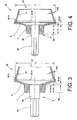
- the rotor cup 26 of the FIG. 3 differs from the rotor cup 26 according to the FIG. 4 essentially by the shape of its rotor groove 33A and 33B, respectively.
- FIG. 4 illustrated rotor cup 26, a so-called T-rotor has a pointed rotor groove 33 B with a relatively long, radially arranged support 40 B in the region of the rotor bottom 6.
- Such trained rotor cups 26 are relatively insensitive to dirt deposits.
- can be 26 produce yarns with such rotor cups, which are ring yarn similar in yarn structure and yarn volume.
- the distance d or d 1 of the center of mass of the rotor cup 26 from the stop edge 60 of the rotor cup 26 is preferably between 5.88 mm and 7.51 mm in these rotors.
- rotor cup 26 a so-called G-rotor, has a relation to a T-rotor less pointed rotor groove 33A, which also has only a relatively short radially arranged support 40A.
- Such trained rotor cups 26 are indeed much more sensitive to dirt deposits, but allow the production of a voluminous, soft yarn.
- FIG. 3 can be seen in such rotor cups 26 of the center of gravity, also depending on the respective rotor diameter D, slightly spaced from the rotor groove 33A at the level of the inner region of the rotor base 6, that is, approximately at the level of in the FIG. 3 with 50B designated section.
- these G-rotors is the center of gravity of the rotor cup at a distance b or b 1 from a stop edge of the rotor cup, which is between 5.75 mm and 7.06 mm.
Landscapes
- Engineering & Computer Science (AREA)
- Mechanical Engineering (AREA)
- Textile Engineering (AREA)
- Spinning Or Twisting Of Yarns (AREA)
Abstract
Claims (7)
- Rotor de filage (3) à bout ouvert pour une machine textile produisant des bobines croisées, avec un arbre de rotor (4) monté à rotation à l'aide d'un système de palier magnétique, et avec une cuvette de rotor (26) qui présente une ouverture frontale de rotor (30), une paroi (31) de glissement de fibres partant de l'ouverture du rotor, une « rainure de rotor » (33A, 33B) et un fond de rotor (6) sur lequel est formé un collet de raccordement (7), sachant que la cuvette de rotor (26) peut être raccordée à l'arbre de rotor (4) en solidarité de rotation, de manière aisément amovible en cas de besoin, au moyen d'un arbre de raccordement qui peut être fixé en position dans le collet de raccordement (7),
caractérisé en ce que la cuvette de rotor (26) est fabriquée sous la forme d'une construction à paroi mince et est configurée de telle sorte que le barycentre de la cuvette de rotor (26) est disposé dans une région (50B, 50D) qui, considéré depuis l'ouverture de rotor (30), se trouve en arrière de la paroi (31) de glissement des fibres. - Rotor de filage à bout ouvert selon la revendication 1, caractérisé en ce que la cuvette de rotor (26) présente une rainure de rotor (33A) avec un fond de rainure rond et un appui court (40A), disposé radialement, dans la région du fond de rotor (6), sachant que la forme de la rainure de rotor (33A) conjointement avec le diamètre (D) de la rainure de rotor (33A) assure que le barycentre de la cuvette de rotor (26) se situe dans une région (50B) qui est disposée à distance de la rainure de rotor (33A) à hauteur de la région intérieure du fond de rotor (6).
- Rotor de filage à bout ouvert selon la revendication 2, caractérisé en ce que le barycentre de la cuvette de rotor (26) se situe dans une région (50B) qui présente une distance (b ou b1) par rapport à une arête de butée (60) de la cuvette de rotor (26) qui est comprise entre 5,75 mm et 7,06 mm.
- Rotor de filage à bout ouvert selon la revendication 1, caractérisé en ce que la cuvette de rotor (26) présente une rainure de rotor (33B) avec un fond de rainure relativement pointu et un appui relativement long (40B), disposé radialement, dans la région du fond de rotor (6), sachant que la forme de la rainure de rotor (33B) conjointement avec le diamètre (D) de la rainure de rotor (33B) assure que le barycentre de la cuvette de rotor (26) se situe dans une région (50D) qui, en partant de la rainure de rotor (33B), est disposée à hauteur du fond de rotor (6).
- Rotor de filage à bout ouvert selon la revendication 4, caractérisé en ce que le barycentre de la cuvette de rotor (26) se situe dans une région (50D) qui présente une distance (d ou d1) par rapport à une arête de butée (60) de la cuvette de rotor (26) qui est comprise entre 5,88 mm et 7,51 mm.
- Rotor de filage à bout ouvert selon l'une des revendications précédentes, caractérisé en ce que la cuvette de rotor (26) présente une épaisseur de paroi (WS) quasiment constante dans la région de la paroi (31) de glissement des fibres, de la rainure de rotor (33A, 33B) et du fond de rotor (6).
- Rotor de filage à bout ouvert selon la revendication 6, caractérisé en ce que l'épaisseur de paroi (WS) de la cuvette de rotor (26) est inférieure à 1 mm.
Applications Claiming Priority (2)
| Application Number | Priority Date | Filing Date | Title |
|---|---|---|---|
| DE102005062196A DE102005062196A1 (de) | 2005-12-23 | 2005-12-23 | Offenend-Spinnrotor für eine Kreuzspulen herstellende Textilmaschine |
| PCT/EP2006/008907 WO2007079794A1 (fr) | 2005-12-23 | 2006-09-13 | Rotor de filage a extremite ouverte pour machine textile qui fabrique des bobines croisees |
Publications (3)
| Publication Number | Publication Date |
|---|---|
| EP1966421A1 EP1966421A1 (fr) | 2008-09-10 |
| EP1966421B1 true EP1966421B1 (fr) | 2012-08-22 |
| EP1966421B2 EP1966421B2 (fr) | 2020-07-29 |
Family
ID=37441830
Family Applications (1)
| Application Number | Title | Priority Date | Filing Date |
|---|---|---|---|
| EP06792026.4A Active EP1966421B2 (fr) | 2005-12-23 | 2006-09-13 | Rotor de filage a extremite ouverte pour machine textile qui fabrique des bobines croisees |
Country Status (4)
| Country | Link |
|---|---|
| EP (1) | EP1966421B2 (fr) |
| CN (1) | CN101316957B (fr) |
| DE (1) | DE102005062196A1 (fr) |
| WO (1) | WO2007079794A1 (fr) |
Cited By (1)
| Publication number | Priority date | Publication date | Assignee | Title |
|---|---|---|---|---|
| EP3249085A2 (fr) | 2016-05-24 | 2017-11-29 | Rieter Ingolstadt GmbH | Arbre de rotor pour un rotor de filage monté sans contact dans un système de paliers magnétiques et rotor de filage |
Families Citing this family (8)
| Publication number | Priority date | Publication date | Assignee | Title |
|---|---|---|---|---|
| CZ2012590A3 (cs) * | 2012-08-30 | 2014-03-12 | Rieter Cz S.R.O. | Spřádací rotor pro uložení v elektromagnetickém ložiskovém a hnacím systému pracovního místa rotorového dopřádacího stroje a způsob jeho výroby |
| DE102012022092A1 (de) * | 2012-11-10 | 2014-05-15 | Saurer Germany Gmbh & Co. Kg | Offenend-Spinnrotor |
| DE102015007819A1 (de) * | 2015-06-18 | 2016-12-22 | Saurer Germany Gmbh & Co. Kg | Spinnrotor für eine mit hohen Rotordrehzahlen arbeitende Offenend-Spinnvorrichtung |
| CH711652A1 (de) * | 2015-10-16 | 2017-04-28 | Rieter Ag Maschf | Spindelunterteil für Spindeln einer Ringspinnmaschine. |
| DE102016122595A1 (de) * | 2016-11-23 | 2018-05-24 | Maschinenfabrik Rieter Ag | Rotortasse und Offenend-Spinnrotor mit einer Rotortasse |
| CN108360097B (zh) * | 2018-03-27 | 2023-08-04 | 杭州三相科技有限公司 | 电机前置的独立直驱式超高速转杯结构及其集群控制系统 |
| DE102018112081A1 (de) * | 2018-05-18 | 2019-11-21 | Rieter Ingolstadt Gmbh | Verfahren zum Einstellen einer axialen Position eines Rotorantriebs, Rotorspinnvorrichtung, Spinnmaschine sowie Einstelllehre und Sensor |
| CN221320205U (zh) | 2023-09-28 | 2024-07-12 | 乐擎智能科技(苏州)有限公司 | 一种纺纱用转杯 |
Family Cites Families (10)
| Publication number | Priority date | Publication date | Assignee | Title |
|---|---|---|---|---|
| IT1028197B (it) * | 1974-01-30 | 1979-01-30 | Teldix Gmbh | Apparato con un motore in rapida rotazione |
| DE3324129A1 (de) * | 1983-07-05 | 1985-01-17 | Fritz 7347 Bad Überkingen Stahlecker | Lagerung und antrieb fuer einen spinnrotor einer offenend-spinnvorrichtung |
| DE3734545A1 (de) * | 1987-10-13 | 1989-05-03 | Schubert & Salzer Maschinen | Offenend-rotorspinnmaschine |
| DE3844563A1 (de) * | 1988-03-12 | 1989-11-23 | Kernforschungsanlage Juelich | Magnetische lagerung mit permanentmagneten zur aufnahme der radialen lagerkraefte |
| CS271434B1 (en) * | 1988-07-28 | 1990-09-12 | Karel Jindra | Spinning unit for spindleless spinning frame |
| DE4020518A1 (de) * | 1990-06-28 | 1992-01-02 | Schubert & Salzer Maschinen | Offenend-spinnrotor |
| DE4441087A1 (de) * | 1994-11-18 | 1996-05-23 | Rieter Ingolstadt Spinnerei | Offenend-Spinnvorrichtung |
| DE19910277B4 (de) * | 1999-03-09 | 2010-11-04 | Oerlikon Textile Gmbh & Co. Kg | Spinnrotor für Offenend-Spinnmaschinen |
| DE10024020A1 (de) † | 2000-05-16 | 2001-11-22 | Schlafhorst & Co W | Offenend-Spinnrotor |
| DE10254271A1 (de) * | 2002-11-21 | 2004-06-03 | Saurer Gmbh & Co. Kg | Offenend-Spinnvorrichtung |
-
2005
- 2005-12-23 DE DE102005062196A patent/DE102005062196A1/de not_active Withdrawn
-
2006
- 2006-09-13 WO PCT/EP2006/008907 patent/WO2007079794A1/fr not_active Ceased
- 2006-09-13 CN CN2006800443925A patent/CN101316957B/zh active Active
- 2006-09-13 EP EP06792026.4A patent/EP1966421B2/fr active Active
Cited By (2)
| Publication number | Priority date | Publication date | Assignee | Title |
|---|---|---|---|---|
| EP3249085A2 (fr) | 2016-05-24 | 2017-11-29 | Rieter Ingolstadt GmbH | Arbre de rotor pour un rotor de filage monté sans contact dans un système de paliers magnétiques et rotor de filage |
| DE102016109509A1 (de) | 2016-05-24 | 2017-11-30 | Rieter Ingolstadt Gmbh | Rotorschaft für einen in einer Magnetlageranordnung berührungslos gelagerten Spinnrotor und Spinnrotor |
Also Published As
| Publication number | Publication date |
|---|---|
| WO2007079794A1 (fr) | 2007-07-19 |
| EP1966421B2 (fr) | 2020-07-29 |
| CN101316957A (zh) | 2008-12-03 |
| EP1966421A1 (fr) | 2008-09-10 |
| DE102005062196A1 (de) | 2007-06-28 |
| CN101316957B (zh) | 2011-01-12 |
Similar Documents
| Publication | Publication Date | Title |
|---|---|---|
| EP1156142B1 (fr) | Rotor de filage à bout libre | |
| EP1966421B1 (fr) | Rotor de filage a extremite ouverte pour machine textile qui fabrique des bobines croisees | |
| DE19729191B4 (de) | Offenend-Spinnvorrichtung mit einem Spinnrotor | |
| EP2187075B1 (fr) | Palier axial | |
| EP1713961B1 (fr) | Arbre de rotor de filature | |
| EP0925391B1 (fr) | Continu a filer a pots tournants | |
| EP1367154B2 (fr) | Adaptateur de plaque de canalisation pour un dispositif de filature open-end | |
| EP3106550B1 (fr) | Rotor de filature pour métier à filer à bout libre à haute vitesse de rotation | |
| EP1101845B1 (fr) | Palier pour un rotor de filage dans une machine de filature à bout ouvert | |
| EP0926275B1 (fr) | Métier à filer à bout ouvert pour fabriquer des fils à torsion S ou Z | |
| DE3025470C2 (de) | Offenend-Spinnvorrichtung | |
| EP1660708B1 (fr) | Plaque a rainure-guide pour un dispositif de filature a rotor a bout libere | |
| EP1244831B1 (fr) | Procede de filature a fibres liberees, au moyen d'un rotor | |
| DE19642471A1 (de) | Offenend-Spinnvorrichtung mit einem einzelmotorisch angetriebenen Spinnrotor | |
| DE19841406A1 (de) | Offenend-Spinnvorrichtung zum Herstellen von Z- oder S-gedrehten Garnen | |
| DE19859164A1 (de) | Kanalplattenadapter für eine Offenend-Spinnvorrichtung | |
| EP3536835B1 (fr) | Dispositif de canal de guidage de fibres pour un dispositif de filage à extrémité ouverte doté d'une liaison d'encliquetage | |
| EP1422325B1 (fr) | Métier à filer à bout libre comprenant un rotor de filature et procédé de filage | |
| DE102005023517A1 (de) | Offenend-Spinnvorrichtung | |
| DE2421672A1 (de) | Verfahren und vorrichtung zum oespinnen | |
| EP3156527B1 (fr) | Dispositif de filature à rotor à bout libre avec un rotor fileur, stocké avec sa tige de rotor dans le coin d'un palier à disque d'appui | |
| DE10050694A1 (de) | Lagerung für eine Offenend-Spinnvorrichtung | |
| WO2004111320A1 (fr) | Rotor pour un dispositif de filature a rotor a fibres liberees | |
| DE4426203A1 (de) | Auflösewalzenlagerung für eine OE-Spinnvorrichtung | |
| DE2538261B2 (de) | Offenend-Spinneinrichtung |
Legal Events
| Date | Code | Title | Description |
|---|---|---|---|
| PUAI | Public reference made under article 153(3) epc to a published international application that has entered the european phase |
Free format text: ORIGINAL CODE: 0009012 |
|
| 17P | Request for examination filed |
Effective date: 20080723 |
|
| AK | Designated contracting states |
Kind code of ref document: A1 Designated state(s): CZ DE TR |
|
| DAX | Request for extension of the european patent (deleted) | ||
| RBV | Designated contracting states (corrected) |
Designated state(s): CZ DE TR |
|
| GRAP | Despatch of communication of intention to grant a patent |
Free format text: ORIGINAL CODE: EPIDOSNIGR1 |
|
| GRAS | Grant fee paid |
Free format text: ORIGINAL CODE: EPIDOSNIGR3 |
|
| GRAA | (expected) grant |
Free format text: ORIGINAL CODE: 0009210 |
|
| AK | Designated contracting states |
Kind code of ref document: B1 Designated state(s): CZ DE TR |
|
| REG | Reference to a national code |
Ref country code: DE Ref legal event code: R096 Ref document number: 502006011890 Country of ref document: DE Effective date: 20121018 |
|
| PLBI | Opposition filed |
Free format text: ORIGINAL CODE: 0009260 |
|
| 26 | Opposition filed |
Opponent name: RIETER INGOLSTADT GMBH Effective date: 20130522 |
|
| PLAX | Notice of opposition and request to file observation + time limit sent |
Free format text: ORIGINAL CODE: EPIDOSNOBS2 |
|
| REG | Reference to a national code |
Ref country code: DE Ref legal event code: R026 Ref document number: 502006011890 Country of ref document: DE Effective date: 20130522 |
|
| RAP2 | Party data changed (patent owner data changed or rights of a patent transferred) |
Owner name: SAURER GERMANY GMBH & CO. KG |
|
| REG | Reference to a national code |
Ref country code: DE Ref legal event code: R081 Ref document number: 502006011890 Country of ref document: DE Owner name: SAURER GERMANY GMBH & CO. KG, DE Free format text: FORMER OWNER: OERLIKON TEXTILE GMBH & CO. KG, 42897 REMSCHEID, DE Effective date: 20130918 Ref country code: DE Ref legal event code: R081 Ref document number: 502006011890 Country of ref document: DE Owner name: SAURER SPINNING SOLUTIONS GMBH & CO. KG, DE Free format text: FORMER OWNER: OERLIKON TEXTILE GMBH & CO. KG, 42897 REMSCHEID, DE Effective date: 20130918 |
|
| PLBB | Reply of patent proprietor to notice(s) of opposition received |
Free format text: ORIGINAL CODE: EPIDOSNOBS3 |
|
| APBM | Appeal reference recorded |
Free format text: ORIGINAL CODE: EPIDOSNREFNO |
|
| APBP | Date of receipt of notice of appeal recorded |
Free format text: ORIGINAL CODE: EPIDOSNNOA2O |
|
| APAH | Appeal reference modified |
Free format text: ORIGINAL CODE: EPIDOSCREFNO |
|
| APBQ | Date of receipt of statement of grounds of appeal recorded |
Free format text: ORIGINAL CODE: EPIDOSNNOA3O |
|
| REG | Reference to a national code |
Ref country code: DE Ref legal event code: R081 Ref document number: 502006011890 Country of ref document: DE Owner name: SAURER SPINNING SOLUTIONS GMBH & CO. KG, DE Free format text: FORMER OWNER: SAURER GERMANY GMBH & CO. KG, 42897 REMSCHEID, DE |
|
| RAP2 | Party data changed (patent owner data changed or rights of a patent transferred) |
Owner name: SAURER SPINNING SOLUTIONS GMBH & CO. KG |
|
| PGFP | Annual fee paid to national office [announced via postgrant information from national office to epo] |
Ref country code: CZ Payment date: 20190830 Year of fee payment: 14 |
|
| PGFP | Annual fee paid to national office [announced via postgrant information from national office to epo] |
Ref country code: DE Payment date: 20191002 Year of fee payment: 14 |
|
| APBU | Appeal procedure closed |
Free format text: ORIGINAL CODE: EPIDOSNNOA9O |
|
| PUAH | Patent maintained in amended form |
Free format text: ORIGINAL CODE: 0009272 |
|
| STAA | Information on the status of an ep patent application or granted ep patent |
Free format text: STATUS: PATENT MAINTAINED AS AMENDED |
|
| 27A | Patent maintained in amended form |
Effective date: 20200729 |
|
| AK | Designated contracting states |
Kind code of ref document: B2 Designated state(s): CZ DE TR |
|
| REG | Reference to a national code |
Ref country code: DE Ref legal event code: R102 Ref document number: 502006011890 Country of ref document: DE |
|
| PG25 | Lapsed in a contracting state [announced via postgrant information from national office to epo] |
Ref country code: CZ Free format text: LAPSE BECAUSE OF FAILURE TO SUBMIT A TRANSLATION OF THE DESCRIPTION OR TO PAY THE FEE WITHIN THE PRESCRIBED TIME-LIMIT Effective date: 20120822 |
|
| REG | Reference to a national code |
Ref country code: DE Ref legal event code: R119 Ref document number: 502006011890 Country of ref document: DE |
|
| PG25 | Lapsed in a contracting state [announced via postgrant information from national office to epo] |
Ref country code: DE Free format text: LAPSE BECAUSE OF NON-PAYMENT OF DUE FEES Effective date: 20210401 |
|
| PGFP | Annual fee paid to national office [announced via postgrant information from national office to epo] |
Ref country code: TR Payment date: 20240904 Year of fee payment: 19 |