EP3249085A2 - Arbre de rotor pour un rotor de filage monté sans contact dans un système de paliers magnétiques et rotor de filage - Google Patents
Arbre de rotor pour un rotor de filage monté sans contact dans un système de paliers magnétiques et rotor de filage Download PDFInfo
- Publication number
- EP3249085A2 EP3249085A2 EP17169842.6A EP17169842A EP3249085A2 EP 3249085 A2 EP3249085 A2 EP 3249085A2 EP 17169842 A EP17169842 A EP 17169842A EP 3249085 A2 EP3249085 A2 EP 3249085A2
- Authority
- EP
- European Patent Office
- Prior art keywords
- rotor shaft
- rotor
- piece
- spinning
- permanent magnet
- Prior art date
- Legal status (The legal status is an assumption and is not a legal conclusion. Google has not performed a legal analysis and makes no representation as to the accuracy of the status listed.)
- Granted
Links
Images
Classifications
-
- D—TEXTILES; PAPER
- D01—NATURAL OR MAN-MADE THREADS OR FIBRES; SPINNING
- D01H—SPINNING OR TWISTING
- D01H4/00—Open-end spinning machines or arrangements for imparting twist to independently moving fibres separated from slivers; Piecing arrangements therefor; Covering endless core threads with fibres by open-end spinning techniques
- D01H4/04—Open-end spinning machines or arrangements for imparting twist to independently moving fibres separated from slivers; Piecing arrangements therefor; Covering endless core threads with fibres by open-end spinning techniques imparting twist by contact of fibres with a running surface
- D01H4/08—Rotor spinning, i.e. the running surface being provided by a rotor
- D01H4/12—Rotor bearings; Arrangements for driving or stopping
- D01H4/14—Rotor driven by an electric motor
-
- F—MECHANICAL ENGINEERING; LIGHTING; HEATING; WEAPONS; BLASTING
- F16—ENGINEERING ELEMENTS AND UNITS; GENERAL MEASURES FOR PRODUCING AND MAINTAINING EFFECTIVE FUNCTIONING OF MACHINES OR INSTALLATIONS; THERMAL INSULATION IN GENERAL
- F16C—SHAFTS; FLEXIBLE SHAFTS; ELEMENTS OR CRANKSHAFT MECHANISMS; ROTARY BODIES OTHER THAN GEARING ELEMENTS; BEARINGS
- F16C3/00—Shafts; Axles; Cranks; Eccentrics
- F16C3/02—Shafts; Axles
- F16C3/023—Shafts; Axles made of several parts, e.g. by welding
-
- F—MECHANICAL ENGINEERING; LIGHTING; HEATING; WEAPONS; BLASTING
- F16—ENGINEERING ELEMENTS AND UNITS; GENERAL MEASURES FOR PRODUCING AND MAINTAINING EFFECTIVE FUNCTIONING OF MACHINES OR INSTALLATIONS; THERMAL INSULATION IN GENERAL
- F16C—SHAFTS; FLEXIBLE SHAFTS; ELEMENTS OR CRANKSHAFT MECHANISMS; ROTARY BODIES OTHER THAN GEARING ELEMENTS; BEARINGS
- F16C32/00—Bearings not otherwise provided for
- F16C32/04—Bearings not otherwise provided for using magnetic or electric supporting means
- F16C32/0406—Magnetic bearings
- F16C32/044—Active magnetic bearings
- F16C32/0459—Details of the magnetic circuit
- F16C32/0468—Details of the magnetic circuit of moving parts of the magnetic circuit, e.g. of the rotor
-
- F—MECHANICAL ENGINEERING; LIGHTING; HEATING; WEAPONS; BLASTING
- F16—ENGINEERING ELEMENTS AND UNITS; GENERAL MEASURES FOR PRODUCING AND MAINTAINING EFFECTIVE FUNCTIONING OF MACHINES OR INSTALLATIONS; THERMAL INSULATION IN GENERAL
- F16C—SHAFTS; FLEXIBLE SHAFTS; ELEMENTS OR CRANKSHAFT MECHANISMS; ROTARY BODIES OTHER THAN GEARING ELEMENTS; BEARINGS
- F16C32/00—Bearings not otherwise provided for
- F16C32/04—Bearings not otherwise provided for using magnetic or electric supporting means
- F16C32/0406—Magnetic bearings
- F16C32/044—Active magnetic bearings
- F16C32/0474—Active magnetic bearings for rotary movement
- F16C32/0489—Active magnetic bearings for rotary movement with active support of five degrees of freedom, e.g. two radial magnetic bearings combined with an axial bearing
-
- F—MECHANICAL ENGINEERING; LIGHTING; HEATING; WEAPONS; BLASTING
- F16—ENGINEERING ELEMENTS AND UNITS; GENERAL MEASURES FOR PRODUCING AND MAINTAINING EFFECTIVE FUNCTIONING OF MACHINES OR INSTALLATIONS; THERMAL INSULATION IN GENERAL
- F16C—SHAFTS; FLEXIBLE SHAFTS; ELEMENTS OR CRANKSHAFT MECHANISMS; ROTARY BODIES OTHER THAN GEARING ELEMENTS; BEARINGS
- F16C2340/00—Apparatus for treating textiles
- F16C2340/18—Apparatus for spinning or twisting
Definitions
- the present invention relates to a rotor shaft for a non-contact mounted in a magnetic bearing assembly and driven by an electric motor single drive spinning rotor of an open-end spinning device.
- the rotor shaft has a multi-part construction with at least one center piece and at least two outer pieces surrounding the middle piece. The middle piece and the outer pieces are arranged one behind the other in the axial direction of the rotor shaft. Furthermore, the invention relates to a corresponding spinning rotor of an open-end spinning device.
- spinning rotors are often supported with their rotor shaft in a magnetic bearing assembly.
- Such magnetic bearing arrangements consist, for example, of two spaced-apart radial magnetic bearings, each of which comprises energizable coils and bearing magnets.
- permanent magnet rings are arranged on the rotor shaft of the spinning rotors, which interact with the bearing magnets or the radial magnetic bearing and rotate with the rotor shaft of the spinning rotor.
- the rotor shaft is further provided with a rotor of the rotor shaft driving single drive.
- Such a spinning rotor with a magnetic bearing assembly is for example in the EP 1 966 421 B1 described. Due to the arrangement of components of the magnetic bearing assembly and the drive on the rotor shaft, the production of such open-end spinning rotors and their assembly in the open-end spinning device is complex.
- the rotor cups of such spinning rotors are therefore usually detachably connected to the rotor shaft in order to enable simple replacement of the spinning element during spinning operation.
- Object of the present invention is to propose a rotor shaft, which is easy to manufacture and can be easily mounted in the open-end spinning device. Furthermore, a corresponding spinning rotor should be proposed.
- a rotor shaft for a non-contact mounted in a magnetic bearing assembly and driven by an electric motor single drive spinning rotor of an open-end spinning device has a multi-part construction.
- the rotor shaft includes at least one central piece and at least two outer pieces surrounding the middle piece, wherein the middle piece and the outer pieces are arranged one behind the other in the axial direction of the rotor shaft.
- the center piece has a cavity in which a cooperating with a stator of the electromotive single drive permanent magnet is arranged.
- the permanent magnet of the electromotive single drive is arranged in the cavity of the center piece, this can be used directly during assembly of the rotor shaft, so that no additional mounting step for the permanent magnet is required. Due to the internal arrangement of the permanent magnet in the cavity further no outside of the rotor shaft protruding parts are present, so that the assembly of the rotor shaft is facilitated in the open-end spinning device.
- the multi-part design of the rotor shaft makes it possible in an advantageous manner to form each of the components of the rotor shaft according to its function and to use a suitable material for each.
- the assembly of the rotor shaft is also particularly simple if the permanent magnet is positioned in the axial direction by one of the outer pieces in the center piece. It is thus only necessary to use the permanent magnet in the cavity. After mounting the corresponding outer piece, the permanent magnet is then correctly positioned with respect to the center piece and thus also correctly with respect to the stator of the open-end spinning device.
- the rotor shaft has an additional connecting piece for connecting the rotor shaft to a rotor cup.
- the connecting piece can have a structurally simple structure in that it merely has to serve the connection of the rotor shaft and the rotor cup, and therefore can also be produced in a simple manner.
- the production of a complex-shaped component, as required in a one-piece rotor shaft, is not required by this.
- the outer pieces may have a simpler structure, if they do not have to include the function of the connection to the rotor cup.
- the rotor shaft includes a first outer piece which has a torque-transmitting coupling device, in particular has a toothing for torque-transmitting connection of the rotor shaft with the rotor cup. Since the first outer piece only has to realize the function of torque transmission to the rotor cup, but does not serve the stable connection of rotor cup and rotor shaft, it may have a simpler structure and thereby again be produced in a favorable manner.
- the rotor shaft includes a second outer piece, which has a receptacle, in particular a cylindrical recess, for a permanent magnet at its front end facing away from the coupling device.
- a permanent magnet for axial magnetic bearing no hereby be integrated in a simple manner in the rotor shaft.
- the outer pieces and the middle piece welded together are.
- the individual components of the rotor shaft can thereby be connected to a particularly high accuracy, the risk of distortion is comparatively low.
- other connections of the outer pieces with the middle piece such as bonding are also conceivable.
- the connecting piece is tubular and has a first, in particular sleeve-shaped, Connection region, with which it is connected to the first outer piece, and a second, preferably also sleeve-shaped, connecting region for connection to the rotor cup.
- the connector can thereby be made particularly inexpensive.
- the assembly of the connecting piece or of the rotor shaft is facilitated by the fact that the tubular connecting piece only has to be pushed onto one of the outer parts of the rotor shaft.
- the connecting piece is tubular, it is furthermore particularly advantageous if the coupling device is arranged at least radially within the second sleeve-shaped connecting region.
- the coupling device can thus be protected against fluff and other contaminants as well as against mechanical damage. In principle, however, it is also conceivable to arrange the coupling device radially outside the sleeve-shaped connection region.
- the connecting piece or one of the outer pieces has a bearing surface of an emergency bearing, in particular a bearing ring, pointing in the axial direction.
- the thrust bearing runs the bearing surface against a complementary trained bearing surface on the open-end spinning device, which forms a favorable friction partner for the bearing surface on the rotor shaft.
- the bearing surface in particular the bearing ring, is made of a metallic material, in particular an aluminum material.
- the bearing surface is also conceivable to produce the bearing surface from a plastic material or a composite material.
- the at least one center piece of the rotor shaft is made of a non-magnetizable material, in particular a stainless steel material, the undisturbed interaction of the inner permanent magnet with the stator of the single drive is possible.
- a plastic or composite material it is conceivable to produce the middle piece from a 3-D printable material, which is possibly still machined after production.
- the at least two outer pieces and / or the connecting piece are made of a magnetizable material, in particular of a high-strength or a stainless steel material.
- a high-strength steel material is meant a material having a minimum yield strength of 355 N / mm 2 . This has a high strength and thereby gives the rotor shaft required for operation with speeds of over 150,000 1 / min stability.
- the magnetizable material of the outer pieces allows the interaction with the radial magnetic bearings.
- the correct axial positioning of the spinning rotor in the magnetic bearing assembly can be further ensured.
- the middle piece has a first receiving area for the first outer piece and a second receiving area for the second outer piece.
- the receiving areas are either sleeve-shaped or constructed as a cylindrical paragraph, so that the outer pieces can be easily plugged onto the center piece or plugged into this.
- the center piece and the outer pieces have the same outer diameter.
- the rotor shaft can thereby be used without problems in the open-end spinning device or be removed therefrom.
- a spinning rotor of an open-end spinning device has such a rotor shaft.
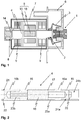
- FIG. 1 shows a schematic sectional view of an open-end spinning device 1.
- the open-end spinning device 1 includes a spinning rotor 2, which is driven by a single drive 5 and is rotatably mounted in a magnetic bearing assembly 8.
- the spinning rotor 2 is arranged in the open-end spinning device 1 such that its rotor cup 3 rotates in a rotor housing 6 subjected to negative pressure, while the rotor shaft 4 of the spinning rotor 2 extends from the rotor housing 6 into a drive housing 7.
- both the single drive 5 and the magnetic bearing assembly 8 are arranged.
- the magnetic bearing assembly in the present case, 8 includes both two spaced-apart radial magnetic bearings 9, which in the present case are designed as active magnetic bearings, as well as an axial bearing 14 also designed as an active magnetic bearing.
- an axial bearing 14 also designed as an active magnetic bearing.
- the individual drive 5 includes a stator 10 with stator windings and is presently arranged between the two radial magnetic bearings 9. Furthermore, the individual drive 5 includes a permanent magnet 18, which is connected to the rotor shaft 4 of the spinning rotor 2, so that the rotor shaft 4 forms the rotor of the single drive 5.
- the rotor shaft 4 of the spinning rotor 2 in this case has a multi-part construction, which in the following with reference to FIG. 2 is explained.
- the rotor shaft 4 is in FIG. 2 shown in a schematic sectional view. It includes according to the present illustration, at least one central piece 15 and at least two outer pieces 16, which are arranged one behind the other in the axial direction.
- the middle piece 15 is made of a non-magnetizable material and has a cavity 17, in which the permanent magnet 18 of the single drive 5 is arranged.
- the two outer pieces 16 are made of a magnetizable material, so that they can interact with the radial magnetic bearing 9 of the open-end spinning device 1. Due to the fact that the outer pieces 16 are made of a magnetizable material, it is not necessary to arrange permanent magnet rings on the rotor shaft 4.
- the rotor shaft 4 comprises only one central piece 15 and only two outer pieces 16 and possibly even a connecting piece 19 is provided for connection to the rotor cup 3.
- each of the outer pieces 16 or the center piece 15 can be manufactured according to its function, whereby the assembly of the rotor shaft 4 from only three or four components is nevertheless easy to carry out.
- FIG. 2 can be removed, the rotor shaft 4, a first outer piece 16a, which has a coupling device 20 for torque-transmitting connection with the rotor cup 3 (s. FIG. 4 ).
- the coupling device 20 is shown here only schematically.
- the permanent magnet 18 is positioned by the assembly of the outer piece 16a at the same time with respect to the rotor shaft 4 and thus with respect to the open-end spinning device 1.
- the rotor shaft 4, a second outer piece 16b which includes a receptacle 21 for a permanent magnet 18 (not shown here) as shown here.
- This can with a magnetic thrust bearing 14 (s. FIG. 1 ) interact.
- a receptacle 21 is only used when the thrust bearing 14 is formed as a magnetic bearing.
- the receptacle 21 is preferably formed as a cylindrical recess 22.
- the middle piece 15 has a first receiving area 23a, which is embodied sleeve-shaped in the present case, so that the first outer piece 16a only has to be inserted into it.
- the first outer piece 16a in turn has a region designed to be complementary to the sleeve-shaped first receiving region 23a.
- the middle piece 15 has a second receiving area 23b. This is presently designed as a cylindrical shoulder, so that the second outer piece 16 b only has to be plugged with a complementary to the second receiving portion 23 b formed area.
- first and second receiving area 23a, 23b is to be understood as an example only. It would also be conceivable to carry out both receiving areas 23a, 23b in the manner of a sleeve or else both receiving areas 23a, 23b as cylindrical shoulders. Finally, the receiving areas 23a, 23b also need not necessarily be cylindrical, but could also have a different geometry. A cylindrical geometry of the receiving areas 23a, 23b, however, allows easy installation.
- the outer pieces 16a, 16b and the middle piece 15 are preferably connected to each other by laser welding, so that the rotor shaft 4 has a high accuracy and a good concentricity.
- the rotor shaft 4 also has a connecting piece 19, which serves to connect to the rotor cup 3, which is not shown here.
- the provision of an additional connecting piece 19 makes it possible in a particularly advantageous manner to machine the outer piece 16a and to introduce the torque-transmitting coupling device 20, in particular also from FIG. 3 seen. Notwithstanding the illustration shown, however, it is not absolutely necessary to provide the torque-transmitting coupling device 20 on one of the outer pieces 16. This could also be attached to the connector 19.
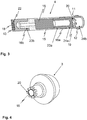
- FIG. 3 shows a further embodiment of a rotor shaft 4 with a coupling device 20.
- the rotor shaft 4 of FIG. 3 In its construction corresponds essentially to the FIG. 2 , so that in the following only on the differences to the FIG. 2 will be discussed in more detail.
- FIG. 3 Removable here again, the permanent magnet 18 is arranged in a cylindrical cavity 17 and is positioned there by the outer piece 16a, which has the torque-transmitting coupling device 20 for the rotor cup in the axial direction.
- the coupling device 20 is presently designed in the form of a toothing. The introduction of the toothing in the front end of the outer piece 16 a is possible in a particularly favorable manner, since the frontal end is freely accessible prior to assembly of the connecting piece 19.
- the coupling device 20 in the form of a separate coupling piece, which is inserted into a bore of the outer piece 16a or possibly also in the first connection portion 24a of the connecting piece 19, in particular pressed or glued, is. It would also be conceivable to form the separate coupling piece as a correspondingly shaped permanent magnet 18, which then fixes the rotor cup 3 in the axial direction on the rotor shaft.
- a permanent magnet 18 is arranged inside a bushing 13 made of a non-magnetizable material such as aluminum, which ensures compliance with a predetermined axial gap in the axial bearing 14.
- the connector 19 is as well as that of FIG. 2 sleeve-shaped or tubular and can thereby be manufactured and mounted in a particularly simple manner.
- the connecting piece 19 For mounting on the rotor shaft 4 or the first outer piece 16a, the connecting piece 19 has a first connecting portion 24a, which is sleeve-shaped and thus only has to be pushed over a complementarily formed cylindrical shoulder of the first outer piece 16a.
- the connection of the connecting piece 19 with the first outer piece 16a preferably takes place again by laser welding.
- the connecting piece 19 furthermore has a second sleeve-shaped connecting region 24b, which connects to the rotor cup 3 (S. FIG. 4 ) serves.
- the rotor cup 3 can thus be easily inserted into the connection region 24b.
- the connection of the rotor cup 3 with the rotor shaft 4 is facilitated because the rotor cup 3 is guided in the sleeve-shaped connection region 24b and thus the assembly of the coupling device 20 is facilitated.
- the tubular design of the connecting piece 19 further advantageously allows the protected arrangement of the coupling device 20 radially and axially within the connecting piece 19.
- a connecting piece 19 for connection to the rotor cup 3 is not absolutely necessary.
- the coupling device 20 could also be designed such that it serves not only the transmission of torque, but at the same time also the connection to the rotor cup 3.
- the present rotor shaft 4 also has a bearing ring 12, which includes a bearing surface 11 of an axial emergency bearing.
- This bearing surface 11 is annular, has in the axial direction and cooperates with a correspondingly formed bearing surface of the open-end spinning device 1, which is not shown here together.
- a bearing surface 11 of an axial emergency bearing in the region of the end face of the rotor shaft 4.
- FIG. 4 shows a rotor cup 3, which carries a complementary to the coupling device 20 of the rotor shaft 4 formed coupling device 20 in the form of a toothing. Furthermore, a permanent magnet 18 is arranged on the rotor cup 3, which holds the rotor cup 3, which is inserted only in the connecting region 24b of the rotor shaft 4, in the axial direction on the rotor shaft 4.
- the permanent magnet 18 to the axial Secure the rotor cup 3 in the rotor shaft 4 in the region of the coupling device 20 or in the region of the outer piece 16a.
- the present rotor shaft 4 has the advantage that due to the magnetic outer pieces 16, it is possible to dispense with additional permanent magnet rings on the rotor shaft 4. Nevertheless, it is possible due to the multi-part design with the non-magnetic center piece 15 to arrange the permanent magnet 18 in the interior of the rotor shaft 4.
- the rotor shaft 4 thereby has a smooth outer peripheral surface with a constant diameter, which facilitates its mounting in the open-end spinning device 1. Since the present rotor shaft 4 comprises only three or four components with the connecting piece 19, it can be assembled in a simple manner despite the multi-part design.
- each of the middle pieces 15 and outer pieces 16 could also be made in two parts, or more than two outer pieces 16 could be provided, even if the overall three-piece design, optionally with an additional connecting piece 19, is particularly advantageous. Further modifications and combinations within the scope of the claims also fall under the invention.
Landscapes
- Engineering & Computer Science (AREA)
- General Engineering & Computer Science (AREA)
- Mechanical Engineering (AREA)
- Textile Engineering (AREA)
- Ocean & Marine Engineering (AREA)
- Spinning Or Twisting Of Yarns (AREA)
Applications Claiming Priority (1)
| Application Number | Priority Date | Filing Date | Title |
|---|---|---|---|
| DE102016109509.5A DE102016109509A1 (de) | 2016-05-24 | 2016-05-24 | Rotorschaft für einen in einer Magnetlageranordnung berührungslos gelagerten Spinnrotor und Spinnrotor |
Publications (3)
| Publication Number | Publication Date |
|---|---|
| EP3249085A2 true EP3249085A2 (fr) | 2017-11-29 |
| EP3249085A3 EP3249085A3 (fr) | 2017-12-20 |
| EP3249085B1 EP3249085B1 (fr) | 2021-10-13 |
Family
ID=58672475
Family Applications (1)
| Application Number | Title | Priority Date | Filing Date |
|---|---|---|---|
| EP17169842.6A Not-in-force EP3249085B1 (fr) | 2016-05-24 | 2017-05-08 | Arbre de rotor pour un rotor de filage monté sans contact dans un système de paliers magnétiques et rotor de filage |
Country Status (3)
| Country | Link |
|---|---|
| EP (1) | EP3249085B1 (fr) |
| CN (1) | CN107630270B (fr) |
| DE (1) | DE102016109509A1 (fr) |
Cited By (1)
| Publication number | Priority date | Publication date | Assignee | Title |
|---|---|---|---|---|
| CN107956009A (zh) * | 2018-01-12 | 2018-04-24 | 浙江华峰氨纶股份有限公司 | 一种氨纶纤维专用磁力假捻装置 |
Families Citing this family (2)
| Publication number | Priority date | Publication date | Assignee | Title |
|---|---|---|---|---|
| DE102019112737A1 (de) * | 2019-05-15 | 2020-11-19 | Maschinenfabrik Rieter Ag | Verfahren zum Betreiben einer Arbeitsstelle einer Rotorspinnmaschine sowie Rotorspinnmaschine |
| DE102022113082A1 (de) | 2022-05-24 | 2023-11-30 | Maschinenfabrik Rieter Ag | Antriebseinheit für einen Spinnrotor einer Rotorspinnvorrichtung |
Citations (2)
| Publication number | Priority date | Publication date | Assignee | Title |
|---|---|---|---|---|
| EP1966421B1 (fr) | 2005-12-23 | 2012-08-22 | Oerlikon Textile GmbH & Co. KG | Rotor de filage a extremite ouverte pour machine textile qui fabrique des bobines croisees |
| DE102014104531A1 (de) | 2014-03-31 | 2015-10-01 | Rieter Cz S.R.O. | Magnetlager, Welle und Wellenlagerung |
Family Cites Families (6)
| Publication number | Priority date | Publication date | Assignee | Title |
|---|---|---|---|---|
| DE19642471B4 (de) * | 1996-10-15 | 2005-05-19 | Saurer Gmbh & Co. Kg | Offenend-Spinnvorrichtung mit einem einzelmotorisch angetriebenen Spinnrotor |
| AUPO484697A0 (en) * | 1997-01-29 | 1997-02-20 | Casttikulm Research Pty Ltd | Improvements in high speed rotor shafts |
| DE19827606A1 (de) * | 1998-06-20 | 1999-12-23 | Schlafhorst & Co W | Lageranordnung für eine Offenend-Spinnvorrichtung |
| DE10024020A1 (de) * | 2000-05-16 | 2001-11-22 | Schlafhorst & Co W | Offenend-Spinnrotor |
| DE102012008693A1 (de) * | 2012-04-28 | 2013-10-31 | Oerlikon Textile Gmbh & Co. Kg | Offenend-Spinnrotor |
| EP2854258B1 (fr) * | 2013-09-26 | 2021-01-20 | SKF Magnetic Mechatronics S.A.S. | Ensemble et procédé d'arbre de rotor à aimant permanent |
-
2016
- 2016-05-24 DE DE102016109509.5A patent/DE102016109509A1/de active Pending
-
2017
- 2017-05-08 EP EP17169842.6A patent/EP3249085B1/fr not_active Not-in-force
- 2017-05-23 CN CN201710367923.4A patent/CN107630270B/zh active Active
Patent Citations (2)
| Publication number | Priority date | Publication date | Assignee | Title |
|---|---|---|---|---|
| EP1966421B1 (fr) | 2005-12-23 | 2012-08-22 | Oerlikon Textile GmbH & Co. KG | Rotor de filage a extremite ouverte pour machine textile qui fabrique des bobines croisees |
| DE102014104531A1 (de) | 2014-03-31 | 2015-10-01 | Rieter Cz S.R.O. | Magnetlager, Welle und Wellenlagerung |
Cited By (2)
| Publication number | Priority date | Publication date | Assignee | Title |
|---|---|---|---|---|
| CN107956009A (zh) * | 2018-01-12 | 2018-04-24 | 浙江华峰氨纶股份有限公司 | 一种氨纶纤维专用磁力假捻装置 |
| CN107956009B (zh) * | 2018-01-12 | 2023-05-12 | 华峰化学股份有限公司 | 一种氨纶纤维专用磁力假捻装置 |
Also Published As
| Publication number | Publication date |
|---|---|
| EP3249085B1 (fr) | 2021-10-13 |
| DE102016109509A1 (de) | 2017-11-30 |
| CN107630270B (zh) | 2022-09-02 |
| CN107630270A (zh) | 2018-01-26 |
| EP3249085A3 (fr) | 2017-12-20 |
Similar Documents
| Publication | Publication Date | Title |
|---|---|---|
| EP2398130B1 (fr) | Petit moteur électrique | |
| DE102014104677B4 (de) | Rotorteil zur Befestigung an der Welle eines rotierenden Elektromotors, Rotor mit Rotorteil, und Verfahren zur Herstellung eines rotierenden Elektromotors und eines Rotors | |
| WO2019141690A1 (fr) | Rotor pour une machine électrique | |
| DE10000253B4 (de) | Antriebssystem | |
| DE102018207585A1 (de) | Magnetkupplung zur kontaktlosen Drehmomentübertragung und Verfahren zur Herstellung einer Magnetkupplung | |
| DE102015014628A1 (de) | Rotorbauelement, Drehachse, Rotor, Motor und Werkzeugmaschine | |
| DE102012206345A1 (de) | Magnetische Reluktanzkupplung mit zwei Rotoren | |
| EP3327187A1 (fr) | Cloche de rotor et rotor pour métier à filer à bout libre doté d'une cloche de rotor | |
| EP3249085B1 (fr) | Arbre de rotor pour un rotor de filage monté sans contact dans un système de paliers magnétiques et rotor de filage | |
| WO2013159843A2 (fr) | Support de rotor et procédé de réalisation d'un support de rotor | |
| EP3153611B1 (fr) | Cloche de rotor de filature à bout libre comprenant un dispositif d'accouplement | |
| EP3391510B1 (fr) | Fixation d'un rotor sur l'arbre d'une machine tournante electrique | |
| DE102012008016A1 (de) | Rotorträger für eine elektrische Maschine, Stützelement für einen Rotorträger und Verfahren zur Herstellung eines Stützelements | |
| DE19542079A1 (de) | Lagerung für einen Offenend-Spinnrotor | |
| EP2822150A2 (fr) | Machine électrique dotée d'un couplage intégré | |
| DE102013110999A1 (de) | Elektromotor | |
| EP2084805A2 (fr) | Stator de moteur électrique | |
| DE102013110998A1 (de) | Elektromotor in Form eines Außenläufermotors | |
| DE102021104468A1 (de) | Verfahren zur Montage einer Axialflussmaschine in ein Gehäuse sowie Axialflussmaschine und Roboter | |
| EP3830931A1 (fr) | Tube de rotor pour machine électrique d'un véhicule | |
| EP4733456A1 (fr) | Rotor de filage à bout libre, arbre de rotor et rotor pour un rotor de filage à bout libre | |
| EP2621670A1 (fr) | Système composé d'une broche de machine-outil et d'un insert y correspondant | |
| EP4501674A1 (fr) | Unité d'entraînement pour véhicule électrique | |
| DE102022129016A1 (de) | Lagerung einer Axialflussmaschine in einem elektromechanischen Achsantriebsstrang | |
| WO2023046514A1 (fr) | Moteur électrique à arbre de rotor |
Legal Events
| Date | Code | Title | Description |
|---|---|---|---|
| PUAI | Public reference made under article 153(3) epc to a published international application that has entered the european phase |
Free format text: ORIGINAL CODE: 0009012 |
|
| STAA | Information on the status of an ep patent application or granted ep patent |
Free format text: STATUS: THE APPLICATION HAS BEEN PUBLISHED |
|
| PUAL | Search report despatched |
Free format text: ORIGINAL CODE: 0009013 |
|
| AK | Designated contracting states |
Kind code of ref document: A2 Designated state(s): AL AT BE BG CH CY CZ DE DK EE ES FI FR GB GR HR HU IE IS IT LI LT LU LV MC MK MT NL NO PL PT RO RS SE SI SK SM TR |
|
| AX | Request for extension of the european patent |
Extension state: BA ME |
|
| AK | Designated contracting states |
Kind code of ref document: A3 Designated state(s): AL AT BE BG CH CY CZ DE DK EE ES FI FR GB GR HR HU IE IS IT LI LT LU LV MC MK MT NL NO PL PT RO RS SE SI SK SM TR |
|
| AX | Request for extension of the european patent |
Extension state: BA ME |
|
| RIC1 | Information provided on ipc code assigned before grant |
Ipc: D01H 4/14 20060101AFI20171113BHEP Ipc: F16C 3/02 20060101ALI20171113BHEP |
|
| STAA | Information on the status of an ep patent application or granted ep patent |
Free format text: STATUS: REQUEST FOR EXAMINATION WAS MADE |
|
| 17P | Request for examination filed |
Effective date: 20180620 |
|
| RBV | Designated contracting states (corrected) |
Designated state(s): AL AT BE BG CH CY CZ DE DK EE ES FI FR GB GR HR HU IE IS IT LI LT LU LV MC MK MT NL NO PL PT RO RS SE SI SK SM TR |
|
| RIN1 | Information on inventor provided before grant (corrected) |
Inventor name: PROELL, ANDREAS JOSEF Inventor name: RIEGER, CONSTANTIN Inventor name: LOOS, BERND Inventor name: SILBER DR., SIEGFRIED |
|
| RIC1 | Information provided on ipc code assigned before grant |
Ipc: D01H 4/14 20060101AFI20210422BHEP Ipc: F16C 3/02 20060101ALI20210422BHEP Ipc: F16C 32/04 20060101ALI20210422BHEP |
|
| GRAP | Despatch of communication of intention to grant a patent |
Free format text: ORIGINAL CODE: EPIDOSNIGR1 |
|
| STAA | Information on the status of an ep patent application or granted ep patent |
Free format text: STATUS: GRANT OF PATENT IS INTENDED |
|
| INTG | Intention to grant announced |
Effective date: 20210610 |
|
| GRAS | Grant fee paid |
Free format text: ORIGINAL CODE: EPIDOSNIGR3 |
|
| GRAA | (expected) grant |
Free format text: ORIGINAL CODE: 0009210 |
|
| STAA | Information on the status of an ep patent application or granted ep patent |
Free format text: STATUS: THE PATENT HAS BEEN GRANTED |
|
| AK | Designated contracting states |
Kind code of ref document: B1 Designated state(s): AL AT BE BG CH CY CZ DE DK EE ES FI FR GB GR HR HU IE IS IT LI LT LU LV MC MK MT NL NO PL PT RO RS SE SI SK SM TR |
|
| REG | Reference to a national code |
Ref country code: GB Ref legal event code: FG4D Free format text: NOT ENGLISH |
|
| RIN1 | Information on inventor provided before grant (corrected) |
Inventor name: SILBER DR., SIEGFRIED Inventor name: PROELL, ANDREAS JOSEF Inventor name: RIEGER, CONSTANTIN Inventor name: LOOS, BERND |
|
| REG | Reference to a national code |
Ref country code: CH Ref legal event code: EP |
|
| REG | Reference to a national code |
Ref country code: DE Ref legal event code: R096 Ref document number: 502017011705 Country of ref document: DE |
|
| REG | Reference to a national code |
Ref country code: IE Ref legal event code: FG4D Free format text: LANGUAGE OF EP DOCUMENT: GERMAN |
|
| REG | Reference to a national code |
Ref country code: AT Ref legal event code: REF Ref document number: 1438254 Country of ref document: AT Kind code of ref document: T Effective date: 20211115 |
|
| RAP4 | Party data changed (patent owner data changed or rights of a patent transferred) |
Owner name: RIETER INGOLSTADT GMBH |
|
| REG | Reference to a national code |
Ref country code: LT Ref legal event code: MG9D |
|
| REG | Reference to a national code |
Ref country code: NL Ref legal event code: MP Effective date: 20211013 |
|
| PG25 | Lapsed in a contracting state [announced via postgrant information from national office to epo] |
Ref country code: RS Free format text: LAPSE BECAUSE OF FAILURE TO SUBMIT A TRANSLATION OF THE DESCRIPTION OR TO PAY THE FEE WITHIN THE PRESCRIBED TIME-LIMIT Effective date: 20211013 Ref country code: LT Free format text: LAPSE BECAUSE OF FAILURE TO SUBMIT A TRANSLATION OF THE DESCRIPTION OR TO PAY THE FEE WITHIN THE PRESCRIBED TIME-LIMIT Effective date: 20211013 Ref country code: FI Free format text: LAPSE BECAUSE OF FAILURE TO SUBMIT A TRANSLATION OF THE DESCRIPTION OR TO PAY THE FEE WITHIN THE PRESCRIBED TIME-LIMIT Effective date: 20211013 Ref country code: BG Free format text: LAPSE BECAUSE OF FAILURE TO SUBMIT A TRANSLATION OF THE DESCRIPTION OR TO PAY THE FEE WITHIN THE PRESCRIBED TIME-LIMIT Effective date: 20220113 |
|
| PG25 | Lapsed in a contracting state [announced via postgrant information from national office to epo] |
Ref country code: IS Free format text: LAPSE BECAUSE OF FAILURE TO SUBMIT A TRANSLATION OF THE DESCRIPTION OR TO PAY THE FEE WITHIN THE PRESCRIBED TIME-LIMIT Effective date: 20220213 Ref country code: SE Free format text: LAPSE BECAUSE OF FAILURE TO SUBMIT A TRANSLATION OF THE DESCRIPTION OR TO PAY THE FEE WITHIN THE PRESCRIBED TIME-LIMIT Effective date: 20211013 Ref country code: PT Free format text: LAPSE BECAUSE OF FAILURE TO SUBMIT A TRANSLATION OF THE DESCRIPTION OR TO PAY THE FEE WITHIN THE PRESCRIBED TIME-LIMIT Effective date: 20220214 Ref country code: PL Free format text: LAPSE BECAUSE OF FAILURE TO SUBMIT A TRANSLATION OF THE DESCRIPTION OR TO PAY THE FEE WITHIN THE PRESCRIBED TIME-LIMIT Effective date: 20211013 Ref country code: NO Free format text: LAPSE BECAUSE OF FAILURE TO SUBMIT A TRANSLATION OF THE DESCRIPTION OR TO PAY THE FEE WITHIN THE PRESCRIBED TIME-LIMIT Effective date: 20220113 Ref country code: NL Free format text: LAPSE BECAUSE OF FAILURE TO SUBMIT A TRANSLATION OF THE DESCRIPTION OR TO PAY THE FEE WITHIN THE PRESCRIBED TIME-LIMIT Effective date: 20211013 Ref country code: LV Free format text: LAPSE BECAUSE OF FAILURE TO SUBMIT A TRANSLATION OF THE DESCRIPTION OR TO PAY THE FEE WITHIN THE PRESCRIBED TIME-LIMIT Effective date: 20211013 Ref country code: HR Free format text: LAPSE BECAUSE OF FAILURE TO SUBMIT A TRANSLATION OF THE DESCRIPTION OR TO PAY THE FEE WITHIN THE PRESCRIBED TIME-LIMIT Effective date: 20211013 Ref country code: GR Free format text: LAPSE BECAUSE OF FAILURE TO SUBMIT A TRANSLATION OF THE DESCRIPTION OR TO PAY THE FEE WITHIN THE PRESCRIBED TIME-LIMIT Effective date: 20220114 Ref country code: ES Free format text: LAPSE BECAUSE OF FAILURE TO SUBMIT A TRANSLATION OF THE DESCRIPTION OR TO PAY THE FEE WITHIN THE PRESCRIBED TIME-LIMIT Effective date: 20211013 |
|
| REG | Reference to a national code |
Ref country code: DE Ref legal event code: R097 Ref document number: 502017011705 Country of ref document: DE |
|
| PG25 | Lapsed in a contracting state [announced via postgrant information from national office to epo] |
Ref country code: SM Free format text: LAPSE BECAUSE OF FAILURE TO SUBMIT A TRANSLATION OF THE DESCRIPTION OR TO PAY THE FEE WITHIN THE PRESCRIBED TIME-LIMIT Effective date: 20211013 Ref country code: SK Free format text: LAPSE BECAUSE OF FAILURE TO SUBMIT A TRANSLATION OF THE DESCRIPTION OR TO PAY THE FEE WITHIN THE PRESCRIBED TIME-LIMIT Effective date: 20211013 Ref country code: RO Free format text: LAPSE BECAUSE OF FAILURE TO SUBMIT A TRANSLATION OF THE DESCRIPTION OR TO PAY THE FEE WITHIN THE PRESCRIBED TIME-LIMIT Effective date: 20211013 Ref country code: EE Free format text: LAPSE BECAUSE OF FAILURE TO SUBMIT A TRANSLATION OF THE DESCRIPTION OR TO PAY THE FEE WITHIN THE PRESCRIBED TIME-LIMIT Effective date: 20211013 Ref country code: DK Free format text: LAPSE BECAUSE OF FAILURE TO SUBMIT A TRANSLATION OF THE DESCRIPTION OR TO PAY THE FEE WITHIN THE PRESCRIBED TIME-LIMIT Effective date: 20211013 Ref country code: CZ Free format text: LAPSE BECAUSE OF FAILURE TO SUBMIT A TRANSLATION OF THE DESCRIPTION OR TO PAY THE FEE WITHIN THE PRESCRIBED TIME-LIMIT Effective date: 20211013 |
|
| PLBE | No opposition filed within time limit |
Free format text: ORIGINAL CODE: 0009261 |
|
| STAA | Information on the status of an ep patent application or granted ep patent |
Free format text: STATUS: NO OPPOSITION FILED WITHIN TIME LIMIT |
|
| 26N | No opposition filed |
Effective date: 20220714 |
|
| PG25 | Lapsed in a contracting state [announced via postgrant information from national office to epo] |
Ref country code: AL Free format text: LAPSE BECAUSE OF FAILURE TO SUBMIT A TRANSLATION OF THE DESCRIPTION OR TO PAY THE FEE WITHIN THE PRESCRIBED TIME-LIMIT Effective date: 20211013 |
|
| PG25 | Lapsed in a contracting state [announced via postgrant information from national office to epo] |
Ref country code: SI Free format text: LAPSE BECAUSE OF FAILURE TO SUBMIT A TRANSLATION OF THE DESCRIPTION OR TO PAY THE FEE WITHIN THE PRESCRIBED TIME-LIMIT Effective date: 20211013 |
|
| REG | Reference to a national code |
Ref country code: DE Ref legal event code: R119 Ref document number: 502017011705 Country of ref document: DE |
|
| REG | Reference to a national code |
Ref country code: CH Ref legal event code: PL |
|
| REG | Reference to a national code |
Ref country code: BE Ref legal event code: MM Effective date: 20220531 |
|
| GBPC | Gb: european patent ceased through non-payment of renewal fee |
Effective date: 20220508 |
|
| PG25 | Lapsed in a contracting state [announced via postgrant information from national office to epo] |
Ref country code: MC Free format text: LAPSE BECAUSE OF FAILURE TO SUBMIT A TRANSLATION OF THE DESCRIPTION OR TO PAY THE FEE WITHIN THE PRESCRIBED TIME-LIMIT Effective date: 20211013 Ref country code: LU Free format text: LAPSE BECAUSE OF NON-PAYMENT OF DUE FEES Effective date: 20220508 Ref country code: LI Free format text: LAPSE BECAUSE OF NON-PAYMENT OF DUE FEES Effective date: 20220531 Ref country code: CH Free format text: LAPSE BECAUSE OF NON-PAYMENT OF DUE FEES Effective date: 20220531 |
|
| PG25 | Lapsed in a contracting state [announced via postgrant information from national office to epo] |
Ref country code: IE Free format text: LAPSE BECAUSE OF NON-PAYMENT OF DUE FEES Effective date: 20220508 Ref country code: FR Free format text: LAPSE BECAUSE OF NON-PAYMENT OF DUE FEES Effective date: 20220531 |
|
| PG25 | Lapsed in a contracting state [announced via postgrant information from national office to epo] |
Ref country code: IT Free format text: LAPSE BECAUSE OF FAILURE TO SUBMIT A TRANSLATION OF THE DESCRIPTION OR TO PAY THE FEE WITHIN THE PRESCRIBED TIME-LIMIT Effective date: 20211013 Ref country code: GB Free format text: LAPSE BECAUSE OF NON-PAYMENT OF DUE FEES Effective date: 20220508 Ref country code: DE Free format text: LAPSE BECAUSE OF NON-PAYMENT OF DUE FEES Effective date: 20221201 Ref country code: BE Free format text: LAPSE BECAUSE OF NON-PAYMENT OF DUE FEES Effective date: 20220531 |
|
| REG | Reference to a national code |
Ref country code: AT Ref legal event code: MM01 Ref document number: 1438254 Country of ref document: AT Kind code of ref document: T Effective date: 20220508 |
|
| PG25 | Lapsed in a contracting state [announced via postgrant information from national office to epo] |
Ref country code: AT Free format text: LAPSE BECAUSE OF NON-PAYMENT OF DUE FEES Effective date: 20220508 |
|
| PG25 | Lapsed in a contracting state [announced via postgrant information from national office to epo] |
Ref country code: HU Free format text: LAPSE BECAUSE OF FAILURE TO SUBMIT A TRANSLATION OF THE DESCRIPTION OR TO PAY THE FEE WITHIN THE PRESCRIBED TIME-LIMIT; INVALID AB INITIO Effective date: 20170508 |
|
| PG25 | Lapsed in a contracting state [announced via postgrant information from national office to epo] |
Ref country code: MK Free format text: LAPSE BECAUSE OF FAILURE TO SUBMIT A TRANSLATION OF THE DESCRIPTION OR TO PAY THE FEE WITHIN THE PRESCRIBED TIME-LIMIT Effective date: 20211013 Ref country code: CY Free format text: LAPSE BECAUSE OF FAILURE TO SUBMIT A TRANSLATION OF THE DESCRIPTION OR TO PAY THE FEE WITHIN THE PRESCRIBED TIME-LIMIT Effective date: 20211013 |
|
| PG25 | Lapsed in a contracting state [announced via postgrant information from national office to epo] |
Ref country code: TR Free format text: LAPSE BECAUSE OF FAILURE TO SUBMIT A TRANSLATION OF THE DESCRIPTION OR TO PAY THE FEE WITHIN THE PRESCRIBED TIME-LIMIT Effective date: 20211013 |
|
| PG25 | Lapsed in a contracting state [announced via postgrant information from national office to epo] |
Ref country code: MT Free format text: LAPSE BECAUSE OF FAILURE TO SUBMIT A TRANSLATION OF THE DESCRIPTION OR TO PAY THE FEE WITHIN THE PRESCRIBED TIME-LIMIT Effective date: 20211013 |