EP1968202A1 - Appareil de détermination de sensibilité de réception - Google Patents
Appareil de détermination de sensibilité de réception Download PDFInfo
- Publication number
- EP1968202A1 EP1968202A1 EP06822001A EP06822001A EP1968202A1 EP 1968202 A1 EP1968202 A1 EP 1968202A1 EP 06822001 A EP06822001 A EP 06822001A EP 06822001 A EP06822001 A EP 06822001A EP 1968202 A1 EP1968202 A1 EP 1968202A1
- Authority
- EP
- European Patent Office
- Prior art keywords
- signal
- noise
- reception sensitivity
- level
- residual
- Prior art date
- Legal status (The legal status is an assumption and is not a legal conclusion. Google has not performed a legal analysis and makes no representation as to the accuracy of the status listed.)
- Granted
Links
Images



Classifications
-
- H—ELECTRICITY
- H04—ELECTRIC COMMUNICATION TECHNIQUE
- H04B—TRANSMISSION
- H04B1/00—Details of transmission systems, not covered by a single one of groups H04B3/00 - H04B13/00; Details of transmission systems not characterised by the medium used for transmission
- H04B1/06—Receivers
- H04B1/10—Means associated with receiver for limiting or suppressing noise or interference
- H04B1/1027—Means associated with receiver for limiting or suppressing noise or interference assessing signal quality or detecting noise/interference for the received signal
Definitions
- the present invention relates to a reception sensitivity detection apparatus which is provided, for example, in a radio receiver for receiving radio broadcasts or the like to detect its reception sensitivity.
- Fig. 1(a) is a block diagram illustrating the basic configuration of this conventional FM receiver.
- the receiver allows a front end section to frequency convert an incoming radio wave into an intermediate frequency signal. Then, an intermediate-frequency filter and an amplifier section perform a bandwidth restriction and amplification on the resulting signal so as to convert the signal into an intermediate frequency signal (IF signal) having a desired frequency bandwidth.
- IF signal is then detected at a detection section to yield a detection output for output through an amplifier.
- a smoothing rectifier section serving as reception sensitivity detection means smoothly rectifies the aforementioned IF signal "a" produced at the intermediate-frequency filter and the amplifier section, thereby producing an S meter signal "b" indicative of a reception sensitivity. Based on the voltage level of the S meter signal "b,” the amplification factor of the aforementioned amplifier is automatically adjusted, thereby adjusting the level of the detection output.
- the amplitude of the IF signal "a” takes a level associated with the reception field intensity of the incoming radio wave and the S meter signal "b” takes a voltage level associated with the amplitude of the IF signal "a.” Therefore, automatically adjusting the amplification factor of the amplifier based on the voltage level of the S meter signal "b” is considered possible to output a detection output "c" with a good S/N ratio.
- the aforementioned smoothing rectifier section smoothly rectifies the IF signal "a,” thereby removing an impulsive noise mixed in the IF signal "a” to produce the S meter signal "b.” It is thus considered possible to suppress adverse effects such as impulsive noise so that the amplification factor of the amplifier can be automatically adjusted in accordance with an original reception sensitivity.
- Patent Document 1 Japanese Unexamined Patent Application Publication No. Hei 8-18468
- the aforementioned conventional FM receiver may receive under an environment in which high-energy impulsive noises each occurring at short intervals are produced continually for a long duration.
- the impulsive noises cannot be sufficiently removed at the aforementioned smoothing rectifier section, causing variations in the voltage level of the S meter signal "b" due to the impulsive noise. It may be thus impossible to obtain the voltage level indicative of the original reception sensitivity.
- the receiver will be affected by so-called external noises nz such as ignition noise arising from an automobile igniter, alternator noise arising from a generator, turn signals and horn noise arising from signaling devices, and those noises emitted from other various electrical components.
- external noises nz such as ignition noise arising from an automobile igniter, alternator noise arising from a generator, turn signals and horn noise arising from signaling devices, and those noises emitted from other various electrical components.
- the reception sensitivity is a critical parameter which is used in various processing circuits within the receiver. It is thus important to produce an accurate S meter signal with adverse effects of noise suppressed.
- the present invention has been developed in view of these conventional problems. It is therefore an object of the invention to provide a reception sensitivity detection apparatus which detects reception sensitivity with improved accuracy.
- the invention according to claim 1 provides a reception sensitivity detection apparatus for producing a reception sensitivity signal indicative of a reception sensitivity of a received radio wave.
- the receiver is characterized by including: residual-noise-containing signal generation means for removing a noise component greater than or equal to a predetermined level from those noise components that are contained in an intermediate frequency signal and for producing a residual-noise-containing signal with residual noise components each remaining at a lower level; noise component extracting means for extracting a noise component at a high level, contained in the intermediate frequency signal, as a high-level noise component; noise canceling means for canceling out the residual-noise-containing signal and the high-level noise component to produce a pre-signal; and filter means for filtering the pre-signal to thereby produce a direct current reception sensitivity signal indicative of the reception sensitivity.
- the invention of a receiver according to claim 4 is characterized by including automatic reception control means for providing automatic reception control to a detection output based on the reception sensitivity signal produced by the reception sensitivity detection apparatus at least according to claim 1.
- the invention according to claim 5 provides a reception sensitivity detection method for producing a reception sensitivity signal indicative of a reception sensitivity of a received radio wave.
- the method is characterized by including: a residual-noise-containing signal generation step for removing a noise component greater than or equal to a predetermined level from those noise components that are contained in an intermediate frequency signal and for producing a residual-noise-containing signal with residual noise components each remaining at a lower level; a noise component extracting step for extracting a noise component at a high level, contained in the intermediate frequency signal, as a high-level noise component; a noise canceling step for canceling out the residual-noise-containing signal and the high-level noise component to produce a pre-signal; and a filter step for filtering the pre-signal to thereby produce a direct current reception sensitivity signal indicative of the reception sensitivity.
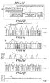
- Fig. 2(a) is a block diagram illustrating the configuration of a reception sensitivity detection apparatus of the present embodiment.
- Figs. 2 (b) to 2 (f) are schematic waveform diagrams illustrating the input or output signal waveform of each component.
- the reception sensitivity detection apparatus 1 is configured to have a residual-noise-containing signal generation section 2, a noise component extracting section 3, a noise canceling section 4, and a filter section 5, in which a reception sensitivity signal (hereinafter referred to as an "S meter signal") Smc indicative of a reception sensitivity is produced from an intermediate frequency signal (IF signal) SIF.
- S meter signal a reception sensitivity signal
- the residual-noise-containing signal generation section 2 receives an IF signal SIF mixed with a noise nz, it removes a noise component greater than or equal to a predetermined level from the noise nz to thereby produce and output a residual-noise-containing signal Sig having a wave form with residual noise components Snza remaining at a lower level.
- a noise component greater than or equal to a predetermined level is received.
- each noise component greater than or equal to a predetermined level is removed from each noise nz to thereby output the residual-noise-containing signal Sig with the residual noise components Snza each remaining at a lower level.
- the noise component extracting section 3 receives the IF signal SIF mixed with the noise nz and the residual-noise-containing signal Sig, and then extracts a high-level noise component Snzb, which is higher in level than the residual noise components Snza contained in the residual-noise-containing signal Sig, from the noise nz mixed in the IF signal SIF for output.
- the noise canceling section 4 removes the high-level noise component Snza from the residual-noise-containing signal Sig to thereby cancel out the aforementioned residual noise component Snza and the high-level noise component Snzb, thus producing and then outputting a pre-signal Sm with significantly reduced noise components. For example, suppose that the noise canceling section 4 receives the residual-noise-containing signal Sig which contains each residual noise component Snza as illustrated in Fig. 2 (c) and receives each high-level noise component Snzb shown in Fig. 2(d) .
- the filter section 5 is formed, for example, of a low-pass type filter (low pass filter) having a predetermined pass band.
- the filter section 5 filters the pre-signal Sm to thereby remove the aforementioned high-frequency noise component remaining in the pre-signal Sm, and then produces and outputs an S meter signal Smc, as illustrated in Fig. 2(f) , which has a direct current voltage level indicative of a reception sensitivity.
- each noise nz mixed in the IF signal SIF is divided into the residual noise component Snza having a lower level and the high-level noise component Snzb having a higher level.
- the residual noise component Snza and the high-level noise component Snzb are canceled out to thereby produce the pre-signal Sm with only high-frequency noise components Snzab remaining at a lower level as illustrated in Fig. 2(e) .
- the pre-signal Sm is then filtered at the filter section 5, thereby making it possible to suppress adverse effects of the noise nz and produce a highly accurate S meter signal Smc which is indicative of a reception sensitivity (i.e., a reception field intensity) with accuracy.
- the IF signal SIF may be mixed with high-energy impulsive noises occurring at short intervals as an external noise nz such as ignition noise arising from an automobile igniter. Even in this case, for each noise nz, the pre-signal Sm is produced in which only lower-level and higher-frequency noise components remain, and then filtered at the filter section 5. It is thus possible to suppress adverse effects of the noise nz and produce a highly accurate S meter signal Smc which is indicative of a reception sensitivity with accuracy.
- gain control can be provided to the detection output. This allows for implementing a receiver with an improved S/N ratio. Furthermore, based on the voltage level of the S meter signal Smc, control can be provided to various processing circuits which are included in the receiver, thereby implementing high-quality reception operations.
- FIG. 3 is a block diagram illustrating the configuration of a reception sensitivity detection apparatus of the present example when installed in an FM receiver. Like or equivalent components in Fig. 3 and Fig. 2 (a) are indicated with like symbols.
- Figs. 4 (a) to 4 (e) are schematic wave form diagrams of the input or output signal waveform of each component expressed on the same time axis throughout the diagrams.
- the receiver includes: an antenna ANT for receiving an incoming radio wave such as broadcast waves; a frontend section 6 for mixing a channel selection local signal and a received high-frequency signal delivered from the antenna ANT to be thereby frequency converted into an intermediate frequency signal; a band pass filter 7 and an intermediate frequency amplification section 8 for amplifying the intermediate frequency signal within a restricted bandwidth to thereby produce an intermediate frequency signal (IF signal) SIF; a detection section 9 for FM detection of the IF signal SIF to thereby output a detection output (hereinafter referred to as the "demodulated signal”) Sdet; and an automatic reception control circuit 10 for providing automatic reception control, discussed later, to the demodulated signal Sdet for output.
- IF signal intermediate frequency signal
- SIF intermediate frequency signal
- detection section 9 for FM detection of the IF signal SIF to thereby output a detection output (hereinafter referred to as the "demodulated signal”) Sdet
- an automatic reception control circuit 10 for providing automatic reception control, discussed later, to the demodulated signal Sde
- the automatic reception control circuit 10 has a soft mute circuit 10a, a separation control circuit 10b, and a high-cut circuit 10c, where each of the circuits 10a, 10b, and 10c performs predetermined processing on the demodulated signal Sdet depending on the voltage level of the S meter signal Smc, discussed later.
- This processing is done when an incoming radio wave varies in field intensity, for example, due to the distance from a sending station to the antenna ANT or when fading has occurred in an incoming radio wave by being affected, for example, by a building or geographical features in the radio transmission path. This allows the automatic reception control circuit 10 to produce and output an output signal Sout that can provide the user with high-quality reproduced sound.
- the soft mute circuit 10a is formed, for example, of an electronic attenuator (attenuation circuit).
- the amplification factor for the demodulated signal Sdet is gradually attenuated from 0 [dB] to thereby yield a signal with a noise component responsible for grating suppressed.
- the attenuated signal is then output as the output signal Sout.
- the separation control circuit 10b stops stereophonic reproduction based on the demodulated signal Sdet to provide control of monophonic reproduction, and outputs the monophonically reproduced signal as the output signal Sout.
- the high-cut circuit 10c is formed of a high-cut filter (i.e. , low-pass filter) which can automatically adjust a cutoff frequency.
- the high-cut circuit 10c lowers the cutoff frequency as the voltage level of the S meter signal Smc decreases by being affected by the aforementioned fading or the like, thereby removing the high-frequency band component of the demodulated signal Sdet.
- the high-cut circuit 10c then outputs a signal with the high-frequency band component removed, i.e., a signal with a high noise component responsible for grating suppressed, as the output signal Sout.
- circuits 10a, 10b, and 10c are connected in series with each other. These circuits 10a, 10b, and 10c use their respective functions mentioned above to perform their respective predetermined processing on and thereby produce the output signal Sout, which is in turn delivered to a loudspeaker (not shown).
- circuits 10a, 10b, and 10c connected in parallel to each other relative to the output from the detection section 9 instead of the circuits 10a, 10b, and 10c connected in series with each other with respect to the output from the detection section 9.
- the relationship between the voltage level of the S meter signal Smc and the effect provided by each of the aforementioned functions of the circuits 10a, 10b, and 10c may be analyzed in accordance with a predetermined algorithm. Any one of the circuits 10a, 10b, and 10c that provides the best listening environment for the user may be selected, so that only the output signal from that circuit selected is output as the output signal Sout.
- the reception sensitivity detection apparatus 1 of the present example has an envelope detection circuit 11 for envelope detection of the IF signal SIF produced at the intermediate frequency amplification section 8, and produces the S meter signal Smc based on an envelope signal SIFev detected.
- the reception sensitivity detection apparatus 1 is configured to include not only the envelope detection circuit 11 but also the residual-noise-containing signal generation section 2, a subtractor 3 corresponding to the noise component extracting section shown in Fig. 2(a) , a subtractor 4 corresponding to the noise canceling section, and a low pass filter 5 corresponding to the filter section.
- the residual-noise-containing signal generation section 2 has a charge and discharge circuit 2a, an amplitude control circuit 2b, a comparator 2c, and a selector circuit 2d.
- the envelope detection circuit 11 uses a rectifier diode (not shown) to rectify the IF signal SIF, and a low pass filter (not shown) having a predetermined cutoff frequency fc1 setting to smooth the rectified signal, thereby outputting the envelope signal SIFev indicative of the envelope of the IF signal SIF. Furthermore, the cutoff frequency fc1 of the aforementioned low-pass filter is set at the center frequency (carrier frequency) of the band pass filter 7 or less or at a like frequency.
- the envelope signal SIFev is delivered therefrom which includes the original envelope of the IF signal SIF and the envelope of the noise nz.
- the charge and discharge circuit 2a is formed of a low pass filter (not shown) having a cutoff frequency fc2 setting lower than the cutoff frequency fc1 of the envelope detection circuit 11 as well as an amplifier (not shown) whose amplification factor Ga can be externally adjusted.
- the amplification factor Ga is set at a factor greater than 1 (for example, a factor of 2).
- the circuit 2a charges and discharges the envelope signal SIFev, which is in turn amplified with the amplification factor Ga to produce a charge and discharge signal Sx for output.
- an envelope signal SIFev containing the envelope of the noisenz (hereinafter referred to as a "noise envelope" Enz) as illustrated with a solid line in Fig. 4 (a) is supplied from the envelope detection circuit 11 to the charge and discharge circuit 2a.
- the charging is initiated at the rising edge of the noise envelope Enz and the discharging is initiated at the falling edge.
- the resulting signal is then amplified with the amplification factor Ga to thereby produce the charge and discharge signal Sx as illustrated with a dotted line.
- the charge and discharge signal Sx shown in Fig. 4 (a) is an example in which the amplification factor Ga has a setting of 2.
- the amplification factor Gb is set at a positive value less than or equal to 1 except 0 (for example, a factor of 0.7).
- the amplitude control signal Sy is produced which is analogous in waveform to the charge and discharge signal Sx and less in level than the charge and discharge signal Sx, as indicated with a chain double-dashed line in Fig. 4 (a) .
- the amplification factor Gb is set at a positive value less than or equal to 1 except 0 as described above to attenuate the charge and discharge signal Sx, and thus, for convenience of explanation, the amplification factor Gb is to be referred to as an attenuation factor Gb.
- the comparator 2c makes a level comparison between the envelope signal SIFev and the charge and discharge signal Sx. As expressed by Equations (1) and (2) below, this allows the comparator 2c to output a switching control signal SW which takes on logic "1" when the level of the envelope signal SIFev is greater than or equal to the level of the charge and discharge signal Sx. The comparator 2c also outputs a switching control signal SW which takes on logic "0" when the level of the envelope signal SIFev is less than the level of the charge and discharge signal Sx.
- the selector circuit 2d is formed, for example, of an analog switch which performs a switching operation based on the switching control signal SW.
- the selector circuit 2d outputs the amplitude control signal Sy when the switching control signal SW is at logic "1" or the envelope signal SIFev when the switching control signal SW is at logic "0.” This allows the selector circuit 2d to output the residual-noise-containing signal Sig having a waveform of a combination of a component of the amplitude control signal Sy and a component of the envelope signal SIFev.
- the selector circuit 2d outputs the original envelope of the IF signal SIF during a period in which the noise envelope Enz is not occurring.
- the amplitude control signal Sy is delivered when the level of the noise envelope Enz is greater than the level of the charge and discharge signal Sx.
- a noise component is delivered which has been attenuated to a lower level due to the aforementioned charging and discharging and with the attenuation factor Gb.
- the noise component of the noise envelope Enz at the lower level is delivered.
- the residual-noise-containing signal Sig which has a wave form of a combination of the original envelope of the IF signal SIF, a lowered-level noise component having been attenuated by the aforementioned charging and discharging and with the attenuation factor Gb, and the lowered-level noise component of the noise envelope Enz.
- the noise component remaining in the residual-noise-containing signal Sig is to be referred to as the residual noise component Snza.
- the subtractor 3 receives the envelope signal SIFev and the residual-noise-containing signal Sig to subtract the residual-noise-containing signal Sig from the envelope signal SIFev, thereby partially extracting a high-level noise component of the noise envelope Enz (hereinafter referred to as the "high-level noise component" Snzb) for output. That is, as illustrated in Fig. 4(c) , the high-level noise component Snzb is extracted which does not contain the original envelope of the IF signal SIF with the residual noise component Snza having been removed from the noise envelope Enz.
- the subtractor 4 receives the residual-noise-containing signal Sig and the high-level noise component Snzb to subtract the high-level noise component Snzb from the residual-noise-containing signal Sig.
- This allows for producing and delivering the pre-signal Sm in which the residual noise component Snza and the high-level noise component Snzb, which are contained in the residual-noise-containing signal Sig, have been canceled out. That is, as illustrated in Fig. 4(d) , the high-level noise component Snzb shown in Fig. 4 (c) is subtracted from the residual noise component Snza remaining at a lowered level as shown in Fig. 4(b) .
- the low pass filter 5 is provided in advance with a predefined filter characteristic setting in order to cut a high-frequency band of the aforementioned high-frequency noise components that are to remain in the pre-signal Sm.
- the low pass filter 5 filters the pre-signal Sm to thereby produce a DC voltage S meter signal Smc for output. Then, based on the voltage level of the S meter signal Smc, the low pass filter 5 controls each of the circuits 10a, 10b, and 10c within the aforementioned automatic reception control circuit 10.
- an external high-energy impulsive noise has caused an IF signal SIF to be mixed with a noise nz, so that an envelope signal SIFev containing the noise envelope Enz of the noise nz is delivered from the envelope detection circuit 11.
- the charge and discharge signal Sx and the amplitude control signal Sy are delivered from the charge and discharge circuit 2a and the amplitude control circuit 2b, respectively.
- the selector circuit 2d when the level of the envelope signal SIFev is greater than the level of the charge and discharge signal Sx, the selector circuit 2d outputs the amplitude control signal Sy based on the switching control signal SW of logic "1" delivered from the comparator 2c. On the other hand, when the level of the envelope signal SIFev is less than the level of the charge and discharge signal Sx, the selector circuit 2d outputs the envelope signal SIFev based on the switching control signal SW of logic "0" delivered from the comparator 2c. As illustrated in Fig. 4(b) , this allows the selector circuit 2d to output the residual-noise-containing signal Sig having the residual noise component Snza.
- the envelope signal SIFev containing the aforementioned noise envelope Enz is also supplied to the subtractor 3, and then the residual-noise-containing signal Sig is subtracted from the envelope signal SIFev, thereby extracting the high-level noise component Snzb as illustrated in Fig. 4(c) . Furthermore, the subtractor 4 produces the high-level noise component Snzb from the residual-noise-containing signal Sig. As illustrated in Fig. 4(d) , the subtractor 4 also subtracts the high-level noise component Snzb from the residual-noise-containing signal Sig, thereby producing a relatively low-level pre-signal Sm in which only a high-frequency noise component remains.
- the pre-signal Sm is filtered in the low pass filter 5 so that the aforementioned high-frequency noise component is removed. This allows for producing a DC voltage S meter signal Smc indicative of a reception sensitivity with adverse effects of the external high-energy impulsive noise suppressed. Then, the resulting signal is supplied to the automatic reception control circuit 10.
- the automatic reception control circuit 10 provides the aforementioned soft mute and separation control and high-cut processing. This allows for producing and delivering an output signal Sout which provides the user with a good listening environment even in the presence of variations in the field intensity of the incoming radio wave or fading of the incoming radio wave caused by being affected by a building or geographical features in the radio transmission path.
- the IF signal SIF mixed with the noise nz is envelope detected, thereby allowing the envelope detection circuit 11 to produce the envelope signal SIFev containing the noise envelope Enz with the high-frequency noise components of the noise nz suppressed in advance. Additionally, a low-level noise component Snza of the noise envelope Enz contained in the residual-noise-containing signal Sig produced at the selector circuit 2d and a high-level noise component Snzb of the noise envelope Enz produced at the subtractor 3 are canceled out at the subtractor 4. This allows for producing the pre-signal Sm with noise components remaining, if any, at a lower level and a higher frequency. The resulting signal is then filtered at the low pass filter 5. It is thus possible to accurately produce a DC voltage S meter signal Smc indicative of a reception sensitivity with adverse effects of noise suppressed.
- the IF signal SIF may be mixed with an external noise nz or a high-energy impulsive noise which occurs continually at short intervals, such as ignition noise arising from an automobile igniter. Even in this case, for each noise nz, a pre-signal Sm is produced in which a lower-level and higher-frequency noise component remains, and then filtered at the low pass filter 5, thereby making it possible to produce a highly accurate S meter signal Smc.
- the automatic reception control circuit 10 performs the soft mute and separation control and high-cut processing on the demodulated signal Sdet. It is thus possible to provide the user with a good listening environment even in the presence of variations in the field intensity of the incoming radio wave or fading of the incoming radio wave caused by being affected by a building or geographical features in the radio transmission path.
- an S meter signal Smc with improved accuracy by externally adjusting at least one of the amplification factor Ga of the charge and discharge circuit 2a and the attenuation factor Gb of the amplitude control circuit 2b. That is, the waveform of the residual noise component Snza to be contained in the residual-noise-containing signal Sig shown in Fig. 4 (b) will vary in accordance with the relative ratio between the amplification factor Ga of the charge and discharge circuit 2a and the attenuation factor Gb of the amplitude control circuit 2b. Moreover, the level and frequency characteristics of the noise component remaining in the pre-signal Sm shown in Fig. 4(d) can be adjusted. Thus, the S meter signal Smc delivered from the low pass filter 5 can be made into a signal that is indicative of a reception sensitivity with improved accuracy.
- the waveform of the residual noise component Snza will be closer in shape to a trapezoidal wave with reduced high-frequency components.
- the amplification factor Ga kept at 2 and an attenuation factor Gb of 0.8, which is greater than 0.7
- the waveform of the residual noise component Snza will have an increased crest depression with increased high-frequency components.
- the aforementioned receiver of the present example is to produce an accurate S meter signal Smc in order not to cause the automatic reception control circuit 10 to provide erroneous control.
- the S meter signal Smc can be used to provide control to various processing circuits included in the receiver, thereby allowing for receiving with high quality.
Landscapes
- Engineering & Computer Science (AREA)
- Computer Networks & Wireless Communication (AREA)
- Signal Processing (AREA)
- Noise Elimination (AREA)
Applications Claiming Priority (2)
| Application Number | Priority Date | Filing Date | Title |
|---|---|---|---|
| JP2005325912 | 2005-11-10 | ||
| PCT/JP2006/320940 WO2007055090A1 (fr) | 2005-11-10 | 2006-10-20 | Appareil de détermination de sensibilité de réception |
Publications (3)
| Publication Number | Publication Date |
|---|---|
| EP1968202A1 true EP1968202A1 (fr) | 2008-09-10 |
| EP1968202A4 EP1968202A4 (fr) | 2010-06-02 |
| EP1968202B1 EP1968202B1 (fr) | 2011-08-10 |
Family
ID=38023097
Family Applications (1)
| Application Number | Title | Priority Date | Filing Date |
|---|---|---|---|
| EP06822001A Not-in-force EP1968202B1 (fr) | 2005-11-10 | 2006-10-20 | Appareil de détermination de sensibilité de réception |
Country Status (3)
| Country | Link |
|---|---|
| EP (1) | EP1968202B1 (fr) |
| JP (1) | JP4650846B2 (fr) |
| WO (1) | WO2007055090A1 (fr) |
Family Cites Families (6)
| Publication number | Priority date | Publication date | Assignee | Title |
|---|---|---|---|---|
| JPH03265221A (ja) * | 1990-03-14 | 1991-11-26 | Pioneer Electron Corp | 受信機 |
| US5311087A (en) * | 1991-07-12 | 1994-05-10 | Pioneer Electronic Corporation | Noise removing circuit |
| JP3286355B2 (ja) * | 1992-09-30 | 2002-05-27 | 三洋電機株式会社 | ノイズキャンセラ |
| JPH0818468A (ja) | 1994-06-29 | 1996-01-19 | Icom Inc | Fm受信機のノイズ抑圧回路 |
| JP4138271B2 (ja) * | 2001-05-25 | 2008-08-27 | 三菱電機株式会社 | 雑音除去装置及びfm受信機 |
| JP2005197813A (ja) * | 2003-12-26 | 2005-07-21 | Pioneer Electronic Corp | ノイズ除去装置および受信機 |
-
2006
- 2006-10-20 EP EP06822001A patent/EP1968202B1/fr not_active Not-in-force
- 2006-10-20 WO PCT/JP2006/320940 patent/WO2007055090A1/fr not_active Ceased
- 2006-10-20 JP JP2007544081A patent/JP4650846B2/ja not_active Expired - Fee Related
Also Published As
| Publication number | Publication date |
|---|---|
| EP1968202B1 (fr) | 2011-08-10 |
| JPWO2007055090A1 (ja) | 2009-04-30 |
| EP1968202A4 (fr) | 2010-06-02 |
| JP4650846B2 (ja) | 2011-03-16 |
| WO2007055090A1 (fr) | 2007-05-18 |
Similar Documents
| Publication | Publication Date | Title |
|---|---|---|
| JP5001302B2 (ja) | Fmトーン除去 | |
| EP2020753B1 (fr) | Récepteur FM | |
| KR100746172B1 (ko) | 프론트앤드회로 | |
| US7676204B2 (en) | Radio receiver having ignition noise detector and method therefor | |
| EP1408616B1 (fr) | Suppresseur de bruit | |
| CN103404039A (zh) | 用于感测相互调制以改善单双调谐器中的无线电性能的方法和设备 | |
| US20100285765A1 (en) | Signal analysis for an improved detection of noise from an adjacent channel | |
| EP0696852A2 (fr) | Récepteur FM | |
| KR100982707B1 (ko) | 경감 장치 및 방법, 그리고 수신 장치 | |
| EP1968202B1 (fr) | Appareil de détermination de sensibilité de réception | |
| KR100572294B1 (ko) | Am 수신 회로 | |
| US8019308B2 (en) | Receiving apparatus | |
| EP1067698B1 (fr) | Récepteur avec détecteur de distorsion d'intermodulation | |
| JPH0879203A (ja) | 雑音抑圧装置 | |
| JP7471748B2 (ja) | ノイズブランカ | |
| JP4650847B2 (ja) | 受信感度検出装置及び受信装置 | |
| JP3602128B2 (ja) | 受信ステレオ−マルチプレクス信号中の障害ノイズを指示する信号の導出回路装置 | |
| JP7164377B2 (ja) | 無線機 | |
| JP4683558B2 (ja) | ミュート回路 | |
| JP7523862B2 (ja) | ノイズブランカ | |
| JP2994431B2 (ja) | ラジオ受信機 | |
| WO2007069445A1 (fr) | Dispositif de detection et dispositif d'elimination de bruit multi-parcours | |
| EP2800279A1 (fr) | Démodulation de signaux audio amortie modulés FM | |
| JPH07105763B2 (ja) | Fmステレオ受信装置 | |
| WO2006059550A1 (fr) | Dispositif de réception et procédé de réception |
Legal Events
| Date | Code | Title | Description |
|---|---|---|---|
| PUAI | Public reference made under article 153(3) epc to a published international application that has entered the european phase |
Free format text: ORIGINAL CODE: 0009012 |
|
| PUAB | Information related to the publication of an a document modified or deleted |
Free format text: ORIGINAL CODE: 0009199EPPU |
|
| PUAF | Information related to the publication of a search report (a3 document) modified or deleted |
Free format text: ORIGINAL CODE: 0009199SEPU |
|
| PUAI | Public reference made under article 153(3) epc to a published international application that has entered the european phase |
Free format text: ORIGINAL CODE: 0009012 |
|
| 17P | Request for examination filed |
Effective date: 20080508 |
|
| AK | Designated contracting states |
Kind code of ref document: A1 Designated state(s): DE FR GB |
|
| DAX | Request for extension of the european patent (deleted) | ||
| RBV | Designated contracting states (corrected) |
Designated state(s): DE FR GB |
|
| A4 | Supplementary search report drawn up and despatched |
Effective date: 20100503 |
|
| RAP1 | Party data changed (applicant data changed or rights of an application transferred) |
Owner name: PIONEER CORPORATION |
|
| RIC1 | Information provided on ipc code assigned before grant |
Ipc: H04B 1/10 20060101AFI20101130BHEP |
|
| GRAP | Despatch of communication of intention to grant a patent |
Free format text: ORIGINAL CODE: EPIDOSNIGR1 |
|
| GRAS | Grant fee paid |
Free format text: ORIGINAL CODE: EPIDOSNIGR3 |
|
| GRAA | (expected) grant |
Free format text: ORIGINAL CODE: 0009210 |
|
| AK | Designated contracting states |
Kind code of ref document: B1 Designated state(s): DE FR GB |
|
| REG | Reference to a national code |
Ref country code: GB Ref legal event code: FG4D |
|
| REG | Reference to a national code |
Ref country code: DE Ref legal event code: R096 Ref document number: 602006023749 Country of ref document: DE Effective date: 20111013 |
|
| PLBE | No opposition filed within time limit |
Free format text: ORIGINAL CODE: 0009261 |
|
| STAA | Information on the status of an ep patent application or granted ep patent |
Free format text: STATUS: NO OPPOSITION FILED WITHIN TIME LIMIT |
|
| 26N | No opposition filed |
Effective date: 20120511 |
|
| REG | Reference to a national code |
Ref country code: DE Ref legal event code: R097 Ref document number: 602006023749 Country of ref document: DE Effective date: 20120511 |
|
| PGFP | Annual fee paid to national office [announced via postgrant information from national office to epo] |
Ref country code: FR Payment date: 20121203 Year of fee payment: 7 |
|
| PGFP | Annual fee paid to national office [announced via postgrant information from national office to epo] |
Ref country code: GB Payment date: 20121031 Year of fee payment: 7 |
|
| REG | Reference to a national code |
Ref country code: GB Ref legal event code: 746 Effective date: 20130311 |
|
| PGFP | Annual fee paid to national office [announced via postgrant information from national office to epo] |
Ref country code: DE Payment date: 20121221 Year of fee payment: 7 |
|
| REG | Reference to a national code |
Ref country code: DE Ref legal event code: R084 Ref document number: 602006023749 Country of ref document: DE Effective date: 20130304 |
|
| GBPC | Gb: european patent ceased through non-payment of renewal fee |
Effective date: 20131020 |
|
| PG25 | Lapsed in a contracting state [announced via postgrant information from national office to epo] |
Ref country code: GB Free format text: LAPSE BECAUSE OF NON-PAYMENT OF DUE FEES Effective date: 20131020 |
|
| REG | Reference to a national code |
Ref country code: DE Ref legal event code: R119 Ref document number: 602006023749 Country of ref document: DE Effective date: 20140501 |
|
| REG | Reference to a national code |
Ref country code: FR Ref legal event code: ST Effective date: 20140630 |
|
| PG25 | Lapsed in a contracting state [announced via postgrant information from national office to epo] |
Ref country code: DE Free format text: LAPSE BECAUSE OF NON-PAYMENT OF DUE FEES Effective date: 20140501 Ref country code: FR Free format text: LAPSE BECAUSE OF NON-PAYMENT OF DUE FEES Effective date: 20131031 |