EP1971000A2 - Connecteur électrique - Google Patents
Connecteur électrique Download PDFInfo
- Publication number
- EP1971000A2 EP1971000A2 EP08250851A EP08250851A EP1971000A2 EP 1971000 A2 EP1971000 A2 EP 1971000A2 EP 08250851 A EP08250851 A EP 08250851A EP 08250851 A EP08250851 A EP 08250851A EP 1971000 A2 EP1971000 A2 EP 1971000A2
- Authority
- EP
- European Patent Office
- Prior art keywords
- latching
- lever
- projection
- connector
- holder
- Prior art date
- Legal status (The legal status is an assumption and is not a legal conclusion. Google has not performed a legal analysis and makes no representation as to the accuracy of the status listed.)
- Withdrawn
Links
Images







Classifications
-
- H—ELECTRICITY
- H01—ELECTRIC ELEMENTS
- H01R—ELECTRICALLY-CONDUCTIVE CONNECTIONS; STRUCTURAL ASSOCIATIONS OF A PLURALITY OF MUTUALLY-INSULATED ELECTRICAL CONNECTING ELEMENTS; COUPLING DEVICES; CURRENT COLLECTORS
- H01R13/00—Details of coupling devices of the kinds covered by groups H01R12/70 or H01R24/00 - H01R33/00
- H01R13/62—Means for facilitating engagement or disengagement of coupling parts or for holding them in engagement
- H01R13/629—Additional means for facilitating engagement or disengagement of coupling parts, e.g. aligning or guiding means, levers, gas pressure electrical locking indicators, manufacturing tolerances
- H01R13/62933—Comprising exclusively pivoting lever
-
- H—ELECTRICITY
- H01—ELECTRIC ELEMENTS
- H01R—ELECTRICALLY-CONDUCTIVE CONNECTIONS; STRUCTURAL ASSOCIATIONS OF A PLURALITY OF MUTUALLY-INSULATED ELECTRICAL CONNECTING ELEMENTS; COUPLING DEVICES; CURRENT COLLECTORS
- H01R13/00—Details of coupling devices of the kinds covered by groups H01R12/70 or H01R24/00 - H01R33/00
- H01R13/62—Means for facilitating engagement or disengagement of coupling parts or for holding them in engagement
- H01R13/629—Additional means for facilitating engagement or disengagement of coupling parts, e.g. aligning or guiding means, levers, gas pressure electrical locking indicators, manufacturing tolerances
-
- H—ELECTRICITY
- H01—ELECTRIC ELEMENTS
- H01R—ELECTRICALLY-CONDUCTIVE CONNECTIONS; STRUCTURAL ASSOCIATIONS OF A PLURALITY OF MUTUALLY-INSULATED ELECTRICAL CONNECTING ELEMENTS; COUPLING DEVICES; CURRENT COLLECTORS
- H01R13/00—Details of coupling devices of the kinds covered by groups H01R12/70 or H01R24/00 - H01R33/00
- H01R13/40—Securing contact members in or to a base or case; Insulating of contact members
- H01R13/42—Securing in a demountable manner
- H01R13/436—Securing a plurality of contact members by one locking piece or operation
- H01R13/4361—Insertion of locking piece perpendicular to direction of contact insertion
-
- H—ELECTRICITY
- H01—ELECTRIC ELEMENTS
- H01R—ELECTRICALLY-CONDUCTIVE CONNECTIONS; STRUCTURAL ASSOCIATIONS OF A PLURALITY OF MUTUALLY-INSULATED ELECTRICAL CONNECTING ELEMENTS; COUPLING DEVICES; CURRENT COLLECTORS
- H01R13/00—Details of coupling devices of the kinds covered by groups H01R12/70 or H01R24/00 - H01R33/00
- H01R13/46—Bases; Cases
- H01R13/502—Bases; Cases composed of different pieces
- H01R13/506—Bases; Cases composed of different pieces assembled by snap action of the parts
-
- H—ELECTRICITY
- H01—ELECTRIC ELEMENTS
- H01R—ELECTRICALLY-CONDUCTIVE CONNECTIONS; STRUCTURAL ASSOCIATIONS OF A PLURALITY OF MUTUALLY-INSULATED ELECTRICAL CONNECTING ELEMENTS; COUPLING DEVICES; CURRENT COLLECTORS
- H01R13/00—Details of coupling devices of the kinds covered by groups H01R12/70 or H01R24/00 - H01R33/00
- H01R13/46—Bases; Cases
- H01R13/52—Dustproof, splashproof, drip-proof, waterproof, or flameproof cases
- H01R13/5219—Sealing means between coupling parts, e.g. interfacial seal
-
- H—ELECTRICITY
- H01—ELECTRIC ELEMENTS
- H01R—ELECTRICALLY-CONDUCTIVE CONNECTIONS; STRUCTURAL ASSOCIATIONS OF A PLURALITY OF MUTUALLY-INSULATED ELECTRICAL CONNECTING ELEMENTS; COUPLING DEVICES; CURRENT COLLECTORS
- H01R13/00—Details of coupling devices of the kinds covered by groups H01R12/70 or H01R24/00 - H01R33/00
- H01R13/62—Means for facilitating engagement or disengagement of coupling parts or for holding them in engagement
- H01R13/629—Additional means for facilitating engagement or disengagement of coupling parts, e.g. aligning or guiding means, levers, gas pressure electrical locking indicators, manufacturing tolerances
- H01R13/62933—Comprising exclusively pivoting lever
- H01R13/62938—Pivoting lever comprising own camming means
-
- H—ELECTRICITY
- H01—ELECTRIC ELEMENTS
- H01R—ELECTRICALLY-CONDUCTIVE CONNECTIONS; STRUCTURAL ASSOCIATIONS OF A PLURALITY OF MUTUALLY-INSULATED ELECTRICAL CONNECTING ELEMENTS; COUPLING DEVICES; CURRENT COLLECTORS
- H01R13/00—Details of coupling devices of the kinds covered by groups H01R12/70 or H01R24/00 - H01R33/00
- H01R13/62—Means for facilitating engagement or disengagement of coupling parts or for holding them in engagement
- H01R13/629—Additional means for facilitating engagement or disengagement of coupling parts, e.g. aligning or guiding means, levers, gas pressure electrical locking indicators, manufacturing tolerances
- H01R13/62933—Comprising exclusively pivoting lever
- H01R13/62955—Pivoting lever comprising supplementary/additional locking means
Definitions
- the present invention relates to an electric connector. More particularly, the present invention relates to an electric connector whose coupling with a counterpart connector is facilitated via manipulation of a manipulation lever.
- Fig. 18 is an exploded perspective view of a related art electric connector.
- the electric connector set forth in US Patent 5647752 has a pair of male and female connectors that couple together, of which the female connector 40 includes a connector housing 41 and a latching lever 44 that is mounted to the housing 41.
- the connector housing 41 has an outer housing 41A at the front and an inner housing 41B at the rear.
- the outer housing 41A is provided, at both sides on the rear edge, with receiving slots 42, 42 that are open at the rear. These receiving slots 42, 42 form a pair, but the reference numeral for one thereof is omitted in Fig. 18 . Likewise below, where items form a pair, the reference numeral for one thereof is omitted.
- each of these engaging portions 43, 43 Facing the receiving slots 42, 42 are engaging portions 43, 43 provided in the inner housing 41B. At the end portion of each of these engaging portions 43, 43 there is provided a flexible engaging piece 43A. During fitting of the flanged projecting portions 45, 45 into the receiving slots 42, 42, these flexible engaging pieces 43A, 43A are resiliently displaced by protrusions 45C, 45C, thus allowing the protrusions 45C, 45C to pass through.
- the latching lever 44 is provided with flanged projecting portions 45, 45 that are turnable around a particular turn axis P running through the two side portions, and that moreover are in positions on the inner surfaces of the two side portions that lie along the turn axis P.
- the flanged projecting portions 45, 45 have columnar pivot portions 45A, 45A, flanges 45B, 45B at the tip portions, and protrusions 45C, 45C that project from the flanges.
- the latching lever 44 is also provided with slide-contact slots 46, 46 on both sides.
- the latching lever 44 To mount the latching lever 44 to the connector housing 41, first the latching lever 44 is moved along the outer housing 41A toward the receiving slots 42, and the flanged projecting portions 45 are inserted into the receiving slots 42. Via such insertion, the pivot portions 45A of the flanged projecting portions 45 of the latching lever 44 are inserted into the U-shaped receiving slots 42 in the rear edges of the outer housing 41A.
- the latching lever 44 is slid along the receiving slots 42, and as a result of such sliding, the protrusions 45C come into sliding contact with the tongue-like flexible engaging pieces 43A of the engaging portions 43 that are provided as integral parts of the inner housing 41B, and the flexible engaging pieces 43A rise up. More precisely, the flexible engaging pieces 43A are pushed outwards.
- the latching lever 44 is pushed in further to a position where the pivot portions 45A reach the innermost part of the receiving slots 42, the protrusions 45C that protrude up from the flanges 45B pass through, exploiting the resilience of the flexible engaging pieces 43A.
- the electric connector set forth in JP-A-2005-123102 is composed of: a plurality of pins; a connector housing in which the pins are housed, a rear holder that is installed to the rear portion of the connector housing and has a plurality of through-holes through which the pins are inserted; a sealing member that is interposed between the connector housing and the rear holder; and a manipulation lever and rear cover that are fitted to the rear portion of the connector housing.
- This electric connector is so configured that sliding of the rear cover results in the rear holder being fixed to the connector housing, and simultaneously in the sealing member being clamped, so that watertightness is preserved between the outer surfaces of the electric wire portions of the wired pins and the sealing member.
- the mating and latching of the two members can be effected in a simple manner, by the operation of pushing the latching lever onto the connector housing. More precisely, when the flanged projecting portions 45 are inserted into the U-shaped receiving slots 42, the protrusions 45C push the flexible engaging pieces 43A outward, and when the latching lever 44 is pushed in further, the protrusions 45C pass through, exploiting the resilience of the flexible engaging pieces 43A. As a result, the flexible engaging pieces 43A, which had been pushed outward, return to their original positions, and the protrusions 45C are latched by the tips of the flexible engaging pieces. Once latched in this way, the latching lever will not come out of place, even if an external force opposite to the direction in which the latching lever was pushed in should act thereon.
- the protrusions of the flanged projecting portions are merely latched by the end portions of the flexible latching pieces; after such latching, the flexible latching pieces are not locked. Therefore, there is a risk that if some strong external force such as an impact of some kind acts on the latching lever, the flexible latching pieces will be resiliently deformed and the latching of their tip portions and the protrusions will come undone. Should this latching come undone, the connection with the counterpart connector will be rendered faulty, causing the operation of the electric equipment connected to these connectors to be stopped. Further, if the connectors are waterproof type, the watertightness with the counterpart connector will become faulty.
- An advantage of some aspects of the invention is to provide the housing latching portions, cover installation portions and lever mounting portions gathered together on a single member, so as to provide an electric connector in which the shapes of such latching portions, etc., are rendered simple, and which can be assembled in a simple manner.
- Another advantage of the invention is to provide an electric connector whose coupling with a counterpart connector will be firm, so that the manipulation lever will not come out of place even if subjected to a strong external force such as an impact.
- a further advantage of the invention is to provide an electric connector in which the manipulation lever can be fixed via the lever's pivot axles, and hence the manipulation lever fixing means are rendered simple.
- a still further advantage of the invention is to provide an electric connector so configured that it is not possible to mount the rear cover in the wrong direction, and assembly is thus facilitated.
- an electric connector includes: a connector housing inside which pins are housed, and which has at the front an insertion portion into which a counterpart connector is inserted, and at the rear a holder mounting portion; a sealing member that is mounted onto the outer periphery of the holder mounting portion; a rear holder the front end portion of which is a contacting surface for contacting with the sealing member; which has at the front a mating cavity that is fixed onto the holder mounting portion, and at the rear a cover installation portion; and which is fixed to the connector housing with the sealing member interposed; and a rear cover which is mounted to the cover installation portion via sliding motion.
- the electric connector incorporates the features that: the pair of opposed outer walls of the rear holder are formed as a double wall constituted of an inner plate and an outer plate with a gap therebetween, and in such double wall there is formed a housing latching portion with which the connector housing engages, a cover installation portion to which the rear cover is mounted, and a lever mounting portion to which the manipulation lever is mounted.
- the housing latching portions may be formed as a latching arm possessing resilience that are provided on the inner plate, with a latching bar being provided at the end of such latching arm, and a latching slot may be provided in the surface of the connector housing; so that the rear holder is latched to the connector housing via the latching bar being engaged into the latching slot.
- the cover installation portion may be formed as a pair of support projections provided on the inner plate, plus a separation prevention projection provided on the rear wall at the rear of the rear cover, with a flat-bottomed slot being also provided in the rear cover; so that the rear cover is fixed by such support projections and separation prevention projection.
- the lever mounting portion may be formed as a pivot projection provided on the opposed surfaces of the manipulation lever's pair of opposed lever arms, plus a receiving hole that communicate with the gap between the double wall of the rear holder; so that the pivot projection is inserted into such gap through the receiving hole, and the pivot projection is supported so as to be freely rotatable inside the receiving hole.
- the pivot projections may have an axle that rises up from the lever arm and a flange provided on the top of such axle, so that when the pivot projection is inserted into the receiving hole, the flange will be inserted into the aforementioned gap, and the manipulation lever's opposed surface will be brought into contact against the upper plate of the double wall.
- a first cam slot for guidance toward the pivot projection may be provided on the lever arm's opposed surface, a turn restricting portion may be provided on the pivot projection's axle, and a latching projection may be provided on the rear cover's sidewall surface; so that during coupling with the counterpart connector, the rear cover's latching projection will be positioned between the manipulation lever's cam slot and turn restricting portion, and turning of the pivot projection will thereby be restricted.
- a latching slot may be provided adjacent to the turn restricting portion, so that during coupling with the counterpart connector, the latching projection will fit inside such latching slot and the turn restricting portion will contact against the latching projection fitted inside the latching slot, restricting turning of the pivot projection.
- the turn restricting portions may be formed as a flat edge plus a circular edge that are provided on the outer surface of the axle, in such a manner that the flat edge will contact against the latching projection.
- a second cam slot that inhibits mounting of the rear cover may be provided on the opposed surfaces of the pair of lever arms.
- the housing latching portion, cover installation portion and lever mounting portion are provided gathered together in the rear holder; consequently it is a simple matter to form these housing latching portion etc., and moreover it is possible to link these latching portion, etc.
- the connector housing usually houses the pin and their accessories, etc., and therefore has a complex structure, so that providing the aforementioned latching portion, etc., on the connector housing would render the structure thereof even more complex, whereas it is a simple matter to form the latching portion etc., on the rear holder since few other parts are mounted thereto, unlike the connector housing.
- the housing latching portion, cover installation portion and lever mounting portion facilitates linking of these items, so that it is possible, for example, to first link the connector housing to the rear holder via the housing latching portion, then mount the manipulation lever to the lever mounting portion, and follow that with the operation of installing the rear cover to the cover mounting portion, thus effecting assembly of the electric connector in a successive and simple manner.
- the housing latching portion is formed as a latching arm possessing resilience that is provided on the inner plate, with a latching bar being provided at the end of such latching arm, and a latching slot is provided in the surface of the connector housing; so that by engaging the housing latching portion's latching bar into the housing's latching slot, the rear holder can be latched simply and firmly to the connector housing.
- the cover installation portion is formed as a pair of support projections provided on the inner plate, plus a separation prevention projection provided on the rear wall at the rear of the rear cover, with a flat-bottomed slot being provided in the rear cover; so that, by fixing the rear cover via such support projection and separation prevention projection, the rear cover can be installed simply and firmly to the rear holder.
- the lever mounting portion is formed as a pivot projection provided on the opposed surfaces of the manipulation lever's pair of lever arms, plus a receiving hole that communicates with the gap between the rear holder's double wall; so that the manipulation lever can be mounted simply and firmly to the rear holder.
- the pivot projection is formed as an axle that rises up from the lever arm plus a flange provided on the top of such axle, so that when the pivot projection is inserted into the receiving hole, the flange will be inserted into the aforementioned gap, and the manipulation lever's opposed surface will be brought into contact against the upper plate of the double wall.
- a latching slot will preferably be provided adjacent to the turn restricting portion inside the manipulation lever's first cam slot, so that during coupling with the counterpart connector, the latching projection will fit inside such latching slot and the turn restricting portion will contact against the latching projection fitted inside the latching slot, restricting turning of the pivot projection. This will result in firm fixing of the manipulation lever and reliable coupling with the counterpart connector. Further, since turning of the manipulation lever will be restricted when coupling with the counterpart connector is effected, the sealing member mounted to the connector housing will not come loose, and good waterproofing effects will be obtained.
- a second cam slot that inhibit mounting of the rear cover will preferably be provided on the opposed surfaces of the pair of lever arms.
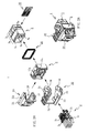
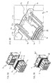
- Fig. 1A is a perspective view of the whole connector and Fig. 1B is an exploded version of the perspective view of Fig. 1A .
- Fig. 2A is a perspective view of the whole connector and Fig. 2B is an exploded version of the perspective view of Fig. 2A .
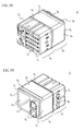
- Fig. 3A is an enlarged perspective view of the connector housing in Fig. 1B
- Fig. 3B is an enlarged perspective view of the connector housing in Fig. 2B .
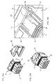
- Fig. 4A is an enlarged perspective view of the rear holder in Fig. 1B
- Fig. 4B is an enlarged perspective view of the rear holder in Fig. 2B .
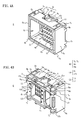
- Fig. 5A is an enlarged perspective view of the rear cover in Fig. 1B
- Fig. 5B is an enlarged perspective view of the rear cover in Fig. 2B .
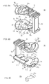
- Fig. 6A is an enlarged perspective view of the manipulation lever in Fig. 1B
- Fig. 6B is an enlarged perspective view of the manipulation lever in Fig. 2B .
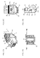
- Fig. 7A is a perspective view with a cut made through the relevant parts
- Fig. 7B is a side view of Fig. 7A .
- FIG. 8A is a perspective view with a cut made through the relevant parts
- Fig. 8B is a side view of Fig. 8A .
- FIG. 9A is a perspective view of the items prior to being joined
- Fig. 9B is a perspective view of the items after being joined
- Fig. 9C is an enlarged sectional view of portion IXC in Fig. 9B .
- Fig. 10A is a perspective view of the items prior to such mounting
- Fig. 10B is a perspective view of the items after such mounting
- Fig. 10C is an enlarged sectional view of portion XC in Fig. 10B .
- FIG. 11A is a perspective view of the items prior to being joined
- Fig. 11B is a perspective view of the items after being joined
- Fig. 11C is an enlarged sectional view of portion XIC in Fig. 11B .
- Fig. 12A is a perspective view of the items prior to being joined
- Fig. 12B is a perspective view of the items in the process of being joined
- Fig. 12C is an enlarged view of portion XIIC in Fig. 12B .
- FIG. 13A Illustrating mounting of the rear cover to the rear holder, Fig. 13A is a plan view, and Figs. 13B to 13D show stepwise the states in the mounting of the rear cover, being sectional views along line XIIIB - XIIIB in Fig. 13A .
- FIG. 14A Illustrating mounting of the rear cover to the rear holder, Fig. 14A is a plan view, and Figs. 14B and 14C show stepwise the states in the mounting of the rear cover, being sectional views along line XIVB - XIVB in Fig. 14A .
- Fig. 15A is a perspective view of the whole connector
- Fig. 15B is an exploded version of the perspective view of Fig. 15A .
- Fig. 16A is a perspective view of the whole
- Fig. 16B is a rear view seen in direction X in Fig. 16A
- Fig. 16C is a sectional view of the housing side of a line cut along XVIC - XVIC in Fig. 16B
- Fig. 16D is a sectional view of the manipulation lever side of a line cut along XVIC - XVIC in Fig. 16B .
- FIG. 17A is a perspective view of the whole
- Fig. 17B is a rear view seen in direction X in Fig. 17A
- Fig. 17C is a sectional view of the housing side of a line cut along XVIIC - XVIIC in Fig. 17B
- Fig. 17D is a sectional view of the manipulation lever side of a line cut along XVIIC - XVIIC in Fig. 17B .
- Fig. 18 is an exploded perspective view of a related art electric connector.
- FIG. 1 the whole of an electric connector according to a first embodiment, and the individual parts composing such connector.
- Figs. 1 and 2 show the whole connector and its individual parts, while Figs. 3 to 6 show the individual parts.
- the arrows between the parts in Figs. 1B and 2B indicate the direction of assembly.
- this electric connector (“connector” below) 1 consists of a female connector, and has a plurality of female pins 2, a female connector housing 3 in which the pins 2 are housed ("connector housing” below), a rear holder 6 that is mounted to the rear of the connector housing 3, a manipulation lever 30 that is mounted to the outer wall of the rear holder 6 and facilitates coupling with the counterpart connector, and a rear cover 20 that is mounted to the rear portion of the rear holder 6 and covers the rear end portions of the pins 2.
- the structure is such that a ring-like sealing member 35 is mounted to the outer periphery wall of the connector housing 3, and a terminal position assurance (“TPA" below) 38 that senses the fitting condition of the pins is mounted to a sidewall of the connector housing 3.
- TPA terminal position assurance
- the female pins 2 are made up of two types of female pin of differing sizes; more precisely, relatively large-sized female pins ("large pins" below) 2 A , and female pins of a smaller size (“small pins” below) 2 B .
- the female pins of each type have a contacting portion at the forward end and a lead wire fixing portion at the rear end, the lead wires being connected to the fixing portions.
- Ring-shaped sealing members 2c are fitted around the outer peripheries of the lead wires of the large pins 2 A .
- the small pins 2 B are gathered into a cluster of, for example, 20 pins, and a ring-like sealing member 2 D is fitted around the periphery of such pin cluster.
- the connector housing 3 is enclosed by roughly rectangular front and rear walls 3 1 , 3 2 at the front and rear and by a pair of opposed top and bottom walls 3 3 , 3 3 and left and right sidewalls 3 4 , 3 4 , around its periphery, and has a front portion constituted of an insertion portion 3 A for insertion of the counterpart connector, and a rear portion constituted of a roughly oblong member having a coupling portion 3 B that is fitted into the rear holder 6.
- Such member is formed as a molding of insulating synthetic resin.
- this connector housing 3 In the interior of this connector housing 3 there are formed, from the rear wall 3 2 towards the front wall 3 1 , through-holes 4 A , 4 B through which the two types of female pins 2 A , 2 B are inserted (see Fig. 3B ). The large pins 2 A are inserted into the through-holes 4 A , and the cluster of small pins 2 B is inserted into the through-hole 4 B .
- the front wall 3 1 there are formed insertion holes for insertion of the male pins of the counterpart connector 40 (see Fig. 15 ) that connect with the pins 2 A , 2 B inserted through the insertion holes 4 A , 4 B in the rear wall 3 2 .
- the front wall 3 1 of the connector housing 3 is divided up by a narrow slot. Division of the front wall 3 1 by such slot means that coupling with the counterpart connector will be smooth, since during insertion into such connector the slot's width will contract.
- a mounting hole 5 B into which the TPA 38 is mounted.
- a flat-bottomed latching groove 5 A into which a latching bar 11 B of the rear holder 6 to be described later (see Fig. 9 ) latches.
- a sidewall portion 5 A' that constitutes the sidewall of the flat-bottomed latching groove 5 A .
- This sidewall portion 5 A is formed as a part of the top wall 3 3 .
- a similar latching groove 5 A and sidewall portion 5 A' are also formed in the bottom wall 3 3 . Further, a rib 3 0 that restricts the motion of the sealing member 35 is formed on the outer periphery of the connector housing 3 at the boundary between the insertion portion 3 A and the holder coupling portion 3 B .
- the rear holder 6 has roughly rectangular front and rear walls 6 1 , 6 2 at the front and rear, and an outer periphery constituted of a member that is enclosed by pairs of opposed outer walls, namely top and bottom walls 6 3 , 6 3 and left and right sidewalls 6 4 , 6 4 .
- Such member is formed as a molding of insulating synthetic resin.
- a mating cavity 6c for insertion of the coupling portion 3 B of the connector housing 3.
- the interior of this mating cavity 6c is partitioned by a partitioning wall 6 D , and in the partitioning wall 6 D there are formed through-holes through which the two types of pin 2 A , 2 B are inserted.
- the top and bottom walls 6 3 , 6 3 are each provided with a cover mounting portion RC and a lever mounting portion LC, to which are mounted a rear cover 20 and a manipulation lever 30 respectively, and with a housing latching portion LA that engages with the connector housing 3.
- the top and the bottom cover mounting portions RC, lever mounting portions LC and housing latching portions LA are each formed with the same structure, and all are formed by molding of the top and bottom walls 6 3 , 6 3 into a particular structure.
- the bottom wall 6 3 and the top wall 6 3 both have the same structure. To avoid duplication in the description therefore, the top wall 6 3 only is described below.
- the top wall 6 3 has a particular thickness and a certain gap 6 G formed between the inner and outer surfaces, being a double wall, or more precisely being composed of an outer plate 6 A and an inner plate 6 B with the gap 6 G interposed.
- This gap 6 G is of a dimension such that the flange 33 B of the manipulation lever 30 to be described later can be inserted therein and turned.
- the outer plate 6 A is foreshortened in the front-rear direction, that is, extends from the front wall 6 1 to a point short of the rear wall 6 2 . In other words, the width of the outer plate 6 A stops short compared to that of the left and right sidewalls 6 4 , 6 4 .
- the rear wall 6 2 is also foreshortened compared to the front wall. It is in between the foreshortened outer plate 6 A and rear wall 6 2 that the cover and lever mounting portions RC, LB and the housing latching portion LA are formed.
- the outer plate 6 A is partitioned by plural slits 8 0 , 8 0 , which extend from the rear edge to shortly before the front wall 6 1 , into three areas, namely into first to third areas 6 A1 to 6 A3 , being in this manner partially divided up.
- the first and third areas 6 A1 and 6 A3 are formed to the same size, while the second area 6 A2 is formed larger than the first and third areas 6 A1 and 6 A3 .
- the second area 6 A2 is further divided into subareas 6 A21 , 6 A21 at the two ends of the recess 9.
- the bottom 9 A of the recess 9 is formed to be flat. Thanks to the recess bottom 9 A being made flat, the cut portion 33 B , of the flange 33 B of the pivot projection 33 to be described later can be aligned with such flat surface, and hence it will be a simple matter to remove the pivot projection 33 from the gap 6 G .
- the rear portions of the first and third areas 6 A1 and 6 A3 are extended past a step difference 6 0 toward the rear wall 6 2 .
- Such extensions constitute support projections 7 A , 7 A of a particular thickness and width.
- the thickness of these support projections 7 A , 7 A is such as to enable insertion into the flat-bottomed slots 22 0 of the rear cover 20.
- the inner plate 6 B is partitioned into five areas, namely into first to fifth areas 6 B1 to 6 B5 , being in this manner partially divided up.
- the first and fifth areas 6 B1 and 6 B5 - the side areas - are the same size.
- the second and fourth areas 6 B2 and 6 B4 are the same size.
- the first and fifth areas 6 B1 and 6 B5 form support projections 7 A , 7 A .
- the third area 6 B3 has a larger surface area than the other areas, and an edge that is extended to the rear.
- a receiving hole 10 A into which the pivot projection 33 of the manipulation lever 30 fits.
- the receiving hole 10 A is formed almost exactly beneath the recess 9 in the outer plate 6 A .
- the receiving hole 10 A communicates with the gap 6 0 .
- a guide surface 10 B which consists of an inclined plane.
- the bottom of the third area 6 B3 forms a surface of the inner wall 6 B , surrounding the mating cavity 6 C , the thickness thereof being such as to enable insertion into the flat-bottomed slots 22 0 of the rear cover 20.
- the support projections 7 A , 7 A and the inner plate 6 B are formed to the same thickness, and are inserted into the flat-bottomed slots 22 0 of the rear cover 20 to be described later.
- the mounting portions 12 A , 12 A are formed into which the rear cover 20 will be inserted.
- a rail projection 6 2A with top and bottom edges projecting outward at particular heights.
- Such a rail projection 6 2A is also formed at the bottom of the rear wall 6 2 . Thanks to the provision of these rail projections 6 2A , the rear cover 20 will, for example, when inserted into one of the fitting portions 12 A , be guided by the rail projections 6 2A and as a result will be held to the rear holder 6, and will not separate from the rear holder 6.
- the rail projections 6 2A are separation prevention projections since they prevent separation of the rear cover 20.
- Latching portions 11, 11 that engage with the connector housing 3 are formed in the second and fourth areas 6 B2 , 6 B4 . These latching portions 11, 11 are formed almost exactly beneath the subareas 6 A21 , 6 A21 of the outer plate 6 A , and have each the same structure.
- these latching portions 11 have: a base portion 11 0 that is joined to the inner plate 6 B ; a latching arm 11 A that extends from the base portion and has a particular length; and, located at the end of the latching arm 11 A , an upper projection that projects upward from the end portion, that is, a projecting block 11 C , and a lower projection that projects downward, that is, a latching bar 11 B .
- the latching arm 11 A is an elastic arm piece possessing resilience.
- the latching bar 11 B engages into the flat-bottomed latching groove 5 A in the connector housing 3.
- the projecting block 11 C performs the role of inhibiting mounting of the rear cover 20 to the rear holder 6 if engagement of the latching bar 11 B with the latching groove 5 A is incomplete. Further, when engagement of the latching bar 11 B with the latching groove 5 A is completely effected, the top of the projecting block 11 C will contact against the sidewall 22 A of the rear cover 20, so that motion of the latching arm 11 A will be restricted, rendering firm the engagement of the latching bar 11 B with the latching groove 5 A . As a result, the connector housing 3 and rear holder 6 will be soundly joined.
- the cover and lever mounting portions RC, LB and the housing latching portion LA are formed between the outer and inner plates 6 A and 6 B and the rear wall 6 2 , as shown in Fig. 4 .
- the cover mounting portion RC is composed principally of the support projections 7 A , 7 A , the inner plate 6 B of the second area 6 B2 between the support projections 7 A , 7 A , and the rail projection 6 2A .
- the lever mounting portion LB is composed principally of the gap 6 G between the inner and outer plates 6 A , 6 B , and the receiving hole 10 A provided in the inner plate 6 B .
- the housing latching portion LA is made up of the latching portions 11, 11 provided in the second and fourth areas 6 B2 , 6 B4 of the inner plate 6 B , and the latching portions 11 are composed of a base portion 11 0 that is joined to the inner plate 6 B , a latching arm 11 A that extends from the base portion and has a particular length, and, located at the end of the latching arm 11 A , a projecting block 11 C that projects upward from the end portion and a latching bar 11 B that projects downward (see Fig. 9C ).
- the housing latching portion LA, cover mounting portion RC and lever mounting portion LB are gathered in the rear holder 6; consequently it is a simple matter to form these, and moreover it is possible to link the cover mounting portion RC and lever mounting portion LB with the housing latching portion LA.
- the connector housing 3 usually houses the pins and their accessories, etc., and therefore has a complex structure, so that providing the above-mentioned latching portion, etc., on the connector housing 3 would render the structure thereof even more complex, whereas it is a simple matter to form the housing latching portion LA, etc., on the rear holder 6 since few other parts are mounted thereon.
- housing latching portion LA cover mounting portion RC
- lever mounting portion LB lever mounting portion LB
- gathering together the housing latching portion LA, cover mounting portion RC and lever mounting portion LB in the rear holder facilitates linking of these items, so that it is possible, for example, to first link the rear holder 6 to the connector housing 3 via the housing latching portion LA, then mount the manipulation lever 30 via the lever mounting portion LB, and then install the rear cover 20 via the cover mounting portion RC, thus effecting assembly of the connector in a successive and simple manner.
- the rear cover 20 is a member for leading out in a particular direction the multiple lead wires that are drawn out from the rear wall 6 2 of the rear holder 6, and has a pair of opposed sidewalls 21, 21 with a space 25 of a particular size therebetween, and a top wall 24 connected to the sidewalls 21, 21, being formed as a molding of insulating synthetic resin.
- the top wall 24 is formed as a curved surface, being joined to the sidewalls 21, 21 at its side and top edges, and having one edge formed as an opening 26.
- the inner interior of this opening 26, that is, at the end portions of the sidewalls 21, 21, is approximately enclosed by an enclosing wall 24 A .
- a projection 24 B onto which the latching portion 32 A of the manipulation lever 30 latches.
- the opening 26 serves as a lead-out hole that leads the lead wires out to the exterior.
- the gap 25 between the pair of sidewalls 21, 21 serves as an insertion opening for insertion of the rear wall 6 2 of the rear holder 6. Since both sidewalls 21, 21 have the same structure, the description below will deal with one sidewall only.
- the sidewall 21 is formed with a thick edge, and in this thick edge there is formed a flat-bottomed slot 22 0 enclosed by opposed first and second sidewall portions 22 A , 22 B . More precisely, the flat-bottomed slot 22 0 has opposed first and second sidewall portions 22 A , 22 B of which one, the first sidewall portion 22 A , constitutes part of the sidewall 21, and the other, the second sidewall portion 22 B , constitutes part of the inner wall. Roughly at the longitudinal center of the outer face of the first sidewall portion 22 A there is formed a latching projection 22c that projects upward. This latching projection 22 C is formed as a roughly square-shaped low-profile projection.
- the latching projection 22c performs a misinsertion prevention role, preventing the rear cover 20 from being mounted in the wrong direction because of the manipulation lever 30 after the manipulation lever 30 has been mounted to the rear holder 6.
- the latching projection 22c also performs the role of fixing the manipulation lever 30 in the required position.
- the space between the first and second sidewall portions 22 A , 22 B or in other words the gap that is the flat-bottomed slot 22 0 , is formed to have a width that is almost the same as or slightly larger than the thickness of the support projections 7 A , 7 A of the rear holder 6.
- the flat-bottomed slot 22 0 serves as a guide slot for when the rear cover 20 is mounted to the rear holder 6, and as an installation slot for the rear cover 20.
- the second sidewall portion 22 B is provided with a guide rail 23.
- the manipulation lever 30 has a pair of opposed lever arms 31, 31, and a connecting piece 32 that connects the lever arms 31, 31, the whole being formed as a molding of insulating synthetic resin.
- Each of the lever arms 31, 31 is constituted of a flat plate body and both have the same structure. More precisely, each lever arm 31 has an outer wall 31 A and an inner wall 31 B , and in each inner wall 31 B there are formed a pivot projection 33 that supports the lever, a cam hole 34, and a pair of first and second cam slots 36, 37.
- the pivot projection 33 is formed to have an axle 33 A whose base rises from the inner wall 31 B of the lever arm 31, and a flange 33 B integrated with the top of the axle 33 A .
- the cam hole 34 runs through both the inner and the outer walls 31 A , 31 B .
- the connecting piece 32 is provided with a latching portion 32 A . During coupling with the counterpart connector 40, this latching portion 32 A is latched onto the projection 29 B of the rear cover 20, thereby fixing the manipulation lever 30 in the required position.
- the manipulation lever 30 is mounted to the rear holder 6 so as to turn freely, but the axle 33 A is provided with a turn restricting portion 33 A' that restricts such turning.
- this turn restricting portion 33 A' is of a teardrop shape, such that its cross-section, supposing the axle 33 A to be cut through in a plane orthogonal to the direction in which the axle 33 A rises up from the lever arm 31, has flat edges 33 A1 and a circular edge 33 A2 .
- the flange 33 B is in the shape of a disc with a cut-off portion 33 B' at the edge, and is of a size that enables insertion into the receiving hole 10 A .
- the provision of the cut-off portion 33 B' facilitates installation to the receiving hole 10 A .
- the pair of first and second cam slots 36, 37 are formed on the side that faces in the opposite direction to the pivot projection 33's direction of insertion. These cam slots 36, 37 are formed by further reducing the thickness of the lever arm 31 past the step difference portion 31 C . More precisely, the first cam slot 36 has: a guide face 36 A over which the latching projection 22c of the rear cover 20 slides; a first stopper 36 1 against which the latching projection 22c contacts; and a latching slot 36 B into which the latching projection 22c latches, the first stopper 36 1 and latching slot 36 B being formed as a part of the step difference portion 31 C .
- the guide face 36 A is formed to extend from the connecting piece 32 toward the edge of the lever arm 31, with a particular width and length.
- the pivot projection 33 is formed in a location near to the first stopper 36 1 .
- the second cam slot 37 is provided on the opposite edge to that where the connecting piece 32 of the lever arm 31 is provided.
- the second cam slot 37 is formed as a reduced-thickness portion with a guide surface 37 A in the inner wall 31 B past the step difference 31 C' .
- This guide surface 37 A of the second cam slot 37 formed past the step difference 31 C' is also a surface over which the latching projection 22c slides, but is formed to have a size that is smaller than the guide surface 36 A of the first cam slot 36.
- the step difference 31 C' serves as a second stopper.
- the cam hole 34 runs through both the inner and the outer walls 31 A , 31 B of the lever arm 31.
- the cam hole 34 has a guide hole 34 A that guides the engaging projection 42 (see Fig. 15 ) of the counterpart connector 40 to be described later.
- a step difference portion 34 B is formed around the guide hole 34 A .
- the flange 42 B of the engaging projection 42 of the counterpart connector 40 latches onto this step difference portion 34 B .
- the sealing member 35 is constituted of a ring-like member with a hollow interior, and is formed from rubber material possessing resilience.
- the outer peripheral surface of this ring-like member will preferably be given an indented-and-protruding form. Rendering the outer peripheral surface indented-and-protruding will make for good watertightness with the counterpart connector 40.
- Figs. 7 and 8 are explanatory views illustrating the mounting of the manipulation lever to the rear holder.
- parts of the rear holder and manipulation lever are excised to facilitate understanding of the internal structure.
- Figs. 8 to 12 are explanatory views illustrating joining of the rear holder to the connector housing, while Figs. 13 and 14 are explanatory views illustrating installation of the rear cover to the rear holder.
- This connector 1 is assembled via the following processes: (I) sealing member mounting process, (II) holder joining process, (III) pin mounting process, (IV) TPA mounting process, (V) lever mounting process, and (VI) rear cover mounting process.
- the sealing member 35 is mounted over the outer surface of the coupling portion 3 B of the connector housing 3 until contact is made with the rib 3 0 , these items being among the connector components shown in, for example, Figs. 1 and 2 .
- the sealing member 35 is mounted as far as the position where it contacts the rib 3 0 , the inner periphery of the sealing member 35 fits tightly against the outer periphery of the connector housing 3, enabling mounting of the rear holder 6.
- Mounting of the sealing member 35 effects a watertight sealing between the housing connector 3 and rear holder 6 to be described later.
- the coupling portion 3 B of the connector housing 3 is inserted into the rear holder 6.
- the latching bar 11 B of the latching portion 11 is sunk into the latching groove 5 A and engages into the mating cavity 6C.
- the rear holder 6 is thereby latched and fixed to the connector housing 3.
- the large pins 2 A and the cluster of small pins 2 B are inserted from the rear of the rear holder 6 through the through-holes 4 A and 4 B , respectively, in the connector housing 3, and thereby both sets of pins are housed and fixed inside the connector housing 3 with the rear holder 6 mounted thereto.
- the TPA 38 is inserted into the mounting hole 5 B in the connector housing 3, fixing the female pins 2 inside the connector housing 3.
- the edges of the flanges 33 B , 33 B enter into the gaps 6 G , 6 G between the inner and outer plates 6 A , 6 B , becoming undislodgeable therefrom, and the manipulation lever 30 is installed in a freely turnable state relative to the rear holder 6.
- the flanges 33 B , 33 B will not be dislodged even if subjected to an external force opposite to that exerted when the manipulation lever 30 was pushed in. This means that after being mounted to the rear holder 6, the manipulation lever 30 will not become detached therefrom even if an impact or other strong external force should act on the manipulation lever 30.
- a gap G (see Fig. 13B ) into which the first sidewall portion of the rear cover 20 will be pushed is formed between the lever arms 31, 31 of the manipulation lever 30 and the inner plates 6 B , 6 B of the rear holder 6.
- This gap G is composed of a first gap G 1 that is opposite the guide surface 36 A of the manipulation lever 30, and a second gap G 2 that is opposite the inner wall 31 B , the first gap G 1 being wider than the second gap G 2 .
- the rear cover 20 is installed to the rear holder 6.
- the rear cover 20 is positioned at the part of the connector housing 3 indicated by arrow A 1 in Fig. 13A , that is, on the side where the manipulation lever 30's connecting piece 32 is located, and the rear cover 20 is inserted in the direction of the first gap G 1 between the rear holder and the manipulation lever 30.
- Such insertion is effected along the direction of one of the mounting portions 12 A , so that one of the support projections 7 A will be inserted into the flat-bottomed slots 22 0 , 22 0 of the rear cover 20.
- the rear cover 20's guide rails 23, 23 will be inserted along the rail projections 6 2A , 6 2A .
- Figs. 11 and 12 are explanatory views illustrating the misassembly, and correspond to Figs. 9 and 10 respectively.
- the sealing member 35 is mounted to the coupling portion 3 B at the rear of the connector housing 3, the mating cavity 6c at the front of the rear holder 6 is mated onto the coupling portion 3 B , and the rear holder 6 is pushed onto the coupling portion 3 B .
- Such pushing-on of the rear holder 6 brings the front wall 6 1 surface of the rear holder 6 into contact with an edge face of the sealing member 35. If the rear holder 6 is incompletely pushed in at this point, then due to the resilience of the latching arm 11 A , the latching bar 11 B of the latching portion 11 will climb on top of the sidewall portion 5 A' of the latching groove 5 A , and the projecting block 11c will be lifted upward (see Fig. 11C ).
- the pair of opposed sidewalls 21, 21 have identical structure, which might pose a risk of the rear cover 20 being mounted in the direction of arrow A 2 in Fig. 14A . If the rear cover 20 were mounted in that direction, the manipulation lever 30 could not be manipulated. Accordingly this connector 1 is so contrived that it is not possible to mount the rear cover 20 in the direction of arrow A 2 . More precisely, if the rear cover 20 is mounted to the rear holder 6 in the direction of arrow A 2 in Fig.
- the first sidewall portion 22 A of the rear cover 20 will enter inside the second gap G 2 , and although the entrance of the second gap G 2 is rendered large by the presence of the manipulation lever 30's second cam slot 37 at such opening, the second cam slot 37's length is less than the width of the first cam slot 36, so that when the rear cover 20 is pushed in further, the latching projection 22c on the sidewall 22 A surface will collide with the step difference portion 31 C' that serves as second stopper, and any further pushing in of the rear cover 20 will be blocked. In this way, mounting of the rear cover 20 in the direction of arrow A 2 is rendered impossible.
- Fig. 15 illustrates the male connector
- Fig. 15A being a perspective view of the whole male connector
- Fig. 15B being an exploded version of the perspective view in Fig. 15A .
- the counterpart connector 40 consists of a male connector, being composed, as Fig. 15 shows, of a plurality of male pins 43 and a male connector housing 41 in which such pins are housed.
- the male pins 43 are composed of relatively large-sized male pins 43 A and smaller-sized male pins 43 B that are connected to the female large pins 2 A and small pins 2 B , respectively, of the connector 1.
- the male connector housing 42 has roughly rectangular front and rear walls 41 1 , 41 2 at the front and rear, and an outer periphery that is enclosed by pairs of opposed outer walls, specifically by upper and lower walls 41s, 41s and left and right sidewalls 41 4 , 41 4 .
- In the front wall 41 1 there is formed a hollow cavity having an insertion opening into which the connector 1 is inserted, and the inner wall of this hollow cavity stands close to the rear wall 41 2 , the whole being formed as a molding of insulating synthetic resin.
- fitting holes 41 A , 41 B into which the male pins 42 fit.
- engaging projections 42, 42 that project outwards from locations close to the insertion opening.
- These engaging projections 42, 42 are composed of a pivot 42 A that rises from the wall surface, and a flange 42 B that is provided on top of the pivot 42 A ; these are formed to be integrated with the male connector housing 41.
- the flange 42 B is roughly a disc in shape.
- the engaging projections 42 are of a size to engage with the cam holes 34 of the manipulation lever 30 of the connector 1.
- the large pins 43 A and small pins 43 B are inserted into the fitting holes 41 A and 41 B respectively of the male connector housing 41 and fixed therein.
- FIGs. 16 and 17 are explanatory views illustrating coupling of the two connectors, Fig. 16 illustrating the uncoupled and Fig. 17 the coupled state.
- Figs. 16B, 16C , 17B and 17C the counterpart connector 40 is omitted.
- the connector 1 is brought near to the counterpart connector 40, and the insertion portion 3 A of the connector housing 3 located at the front of the connector 1 is inserted into the fitting hole 41 A in the front face of the connector housing 41 of the counterpart connector 40 (see Fig. 16A ).
- the cam holes 34, 34 of the manipulation lever 30 are, as shown in Figs, 16A to 16C , held in positions parallel to the rear holder 6 without being engaged onto the engaging projections 42, 42 of the counterpart connector 40.
- the counterpart connector 40's latching projections 42, 42 are inserted into the open portions of the manipulation lever 30's cam holes 34, 34 as shown in Fig. 17 , after which the manipulation lever 30 is rotated to the rear of the rear cover 20, by grasping the manipulation lever 30's connecting piece 32 between finger and thumb.
- the counterpart connector 40's latching projections 42, 42 are guided into the guide portions of the cam holes 34, 34 and the two connectors 1, 40 are drawn in directions such that they approach each other.
- the connecting piece 32 moves to the rear of the rear cover 20, whereupon coupling of the two connectors 1, 40 is complete and electric contact is effected between the pins 2, 43 of the two connectors 1, 40.
- the manipulation lever 30 Upon such completion of the coupling of the two connectors 1, 40, the manipulation lever 30 is fixed in the position at the rear of the rear cover 20 to which the connecting piece 32 thereof moved.
- the fixing of the manipulation lever 30 in this position is effected as follows.
- the latching projection 22c of the rear cover 20 enters inside the latching groove 36 B , and a flat edge 33 A1 of the turn restricting portion 33 A' contacts against an outer face of the latching projection 22c in such entered state, so that turning of the pivot projection 33 - that is, turning of the manipulation lever 30 - is restricted, as shown in Fig, 17D .
- the manipulation lever 30 will not rock in the arrow C directions.
- latching of the manipulation lever 30 is rendered even more reliable by the fact that the latching portion 32 A provided on the connecting piece 32 latches onto the projection 24 B on the top wall 24 of the rear cover 20.
Landscapes
- Details Of Connecting Devices For Male And Female Coupling (AREA)
- Connector Housings Or Holding Contact Members (AREA)
Applications Claiming Priority (1)
| Application Number | Priority Date | Filing Date | Title |
|---|---|---|---|
| SG200701942-5A SG146466A1 (en) | 2007-03-15 | 2007-03-15 | Electric connector |
Publications (2)
| Publication Number | Publication Date |
|---|---|
| EP1971000A2 true EP1971000A2 (fr) | 2008-09-17 |
| EP1971000A3 EP1971000A3 (fr) | 2014-04-09 |
Family
ID=39434117
Family Applications (1)
| Application Number | Title | Priority Date | Filing Date |
|---|---|---|---|
| EP08250851.6A Withdrawn EP1971000A3 (fr) | 2007-03-15 | 2008-03-13 | Connecteur électrique |
Country Status (5)
| Country | Link |
|---|---|
| EP (1) | EP1971000A3 (fr) |
| JP (1) | JP5095431B2 (fr) |
| KR (1) | KR101400581B1 (fr) |
| CN (1) | CN101299500B (fr) |
| SG (1) | SG146466A1 (fr) |
Cited By (4)
| Publication number | Priority date | Publication date | Assignee | Title |
|---|---|---|---|---|
| CN102610963A (zh) * | 2011-01-20 | 2012-07-25 | 泰科电子(上海)有限公司 | 电连接器组件 |
| CN104659535A (zh) * | 2013-11-19 | 2015-05-27 | 住友电装株式会社 | 防水连接器 |
| WO2020025087A1 (fr) * | 2018-08-02 | 2020-02-06 | Harting Electric Gmbh & Co. Kg | Système de connecteur enfichable modulaire |
| CN118431810A (zh) * | 2024-07-04 | 2024-08-02 | 比亚迪股份有限公司 | 护套、连接器及车辆 |
Families Citing this family (8)
| Publication number | Priority date | Publication date | Assignee | Title |
|---|---|---|---|---|
| KR101595364B1 (ko) * | 2009-09-24 | 2016-02-19 | 한국단자공업 주식회사 | 커넥터 어셈블리 |
| WO2014115349A1 (fr) * | 2013-01-25 | 2014-07-31 | 住友電装株式会社 | Connecteur à levier |
| JP2016126841A (ja) * | 2014-12-26 | 2016-07-11 | 住友電装株式会社 | レバー式コネクタ |
| US10763615B2 (en) * | 2017-06-06 | 2020-09-01 | Nippon Tanshi Co., Ltd. | Connector structure having a longitudinal movement restricting protrusion |
| CN112152013B (zh) | 2019-06-26 | 2022-04-08 | 莫列斯有限公司 | 电连接器和电连接器组件 |
| JP7218268B2 (ja) * | 2019-10-04 | 2023-02-06 | ヒロセ電機株式会社 | 規制部材及びコネクタ組立体 |
| EP3886264B1 (fr) * | 2020-03-27 | 2023-11-08 | Aptiv Technologies Limited | Connecteur électrique étanche |
| JP2023000591A (ja) * | 2021-06-18 | 2023-01-04 | 矢崎総業株式会社 | レバー付きコネクタ |
Citations (2)
| Publication number | Priority date | Publication date | Assignee | Title |
|---|---|---|---|---|
| US5647752A (en) | 1994-05-12 | 1997-07-15 | Yazaki Corporation | Lever-type connector |
| JP2005123102A (ja) | 2003-10-20 | 2005-05-12 | Yazaki Corp | コネクタ |
Family Cites Families (10)
| Publication number | Priority date | Publication date | Assignee | Title |
|---|---|---|---|---|
| JP3316116B2 (ja) * | 1995-09-19 | 2002-08-19 | タイコエレクトロニクスアンプ株式会社 | 電気コネクタ |
| US5938458A (en) * | 1998-06-17 | 1999-08-17 | Molex Incorporated | Lever type electrical connector |
| JP3777083B2 (ja) * | 2000-07-11 | 2006-05-24 | 株式会社オートネットワーク技術研究所 | コネクタ及びコネクタ構造 |
| JP2002270282A (ja) * | 2001-03-12 | 2002-09-20 | Yazaki Corp | 防水コネクタ及び防水コネクタの端子挿通方法 |
| FR2830132A1 (fr) * | 2001-09-24 | 2003-03-28 | Framatome Connectors Int | Connecteur etanche a dispositif de compression de joint |
| US6854992B2 (en) * | 2002-10-18 | 2005-02-15 | Tyco Electronics Corporation | Electrical connector assembly with connection assurance features |
| US6824406B1 (en) * | 2003-06-26 | 2004-11-30 | Delphi Technologies, Inc. | Electrical connector assembly |
| JP4478060B2 (ja) * | 2005-04-08 | 2010-06-09 | 矢崎総業株式会社 | カバー付コネクタ |
| JP4678227B2 (ja) * | 2005-04-22 | 2011-04-27 | 住友電装株式会社 | コネクタ |
| JP4550671B2 (ja) * | 2005-06-09 | 2010-09-22 | タイコエレクトロニクスジャパン合同会社 | レバー式コネクタ |
-
2007
- 2007-03-15 SG SG200701942-5A patent/SG146466A1/en unknown
-
2008
- 2008-02-01 JP JP2008022749A patent/JP5095431B2/ja not_active Expired - Fee Related
- 2008-03-13 EP EP08250851.6A patent/EP1971000A3/fr not_active Withdrawn
- 2008-03-14 KR KR1020080023913A patent/KR101400581B1/ko not_active Expired - Fee Related
- 2008-03-14 CN CN2008100860619A patent/CN101299500B/zh not_active Expired - Fee Related
Patent Citations (2)
| Publication number | Priority date | Publication date | Assignee | Title |
|---|---|---|---|---|
| US5647752A (en) | 1994-05-12 | 1997-07-15 | Yazaki Corporation | Lever-type connector |
| JP2005123102A (ja) | 2003-10-20 | 2005-05-12 | Yazaki Corp | コネクタ |
Cited By (10)
| Publication number | Priority date | Publication date | Assignee | Title |
|---|---|---|---|---|
| CN102610963A (zh) * | 2011-01-20 | 2012-07-25 | 泰科电子(上海)有限公司 | 电连接器组件 |
| CN102610963B (zh) * | 2011-01-20 | 2014-07-09 | 泰科电子(上海)有限公司 | 电连接器组件 |
| CN104659535A (zh) * | 2013-11-19 | 2015-05-27 | 住友电装株式会社 | 防水连接器 |
| CN104659535B (zh) * | 2013-11-19 | 2017-04-12 | 住友电装株式会社 | 防水连接器 |
| WO2020025087A1 (fr) * | 2018-08-02 | 2020-02-06 | Harting Electric Gmbh & Co. Kg | Système de connecteur enfichable modulaire |
| EP3923419A1 (fr) * | 2018-08-02 | 2021-12-15 | HARTING Electric GmbH & Co. KG | Système de connecteur enfichable modulaire |
| RU2764584C1 (ru) * | 2018-08-02 | 2022-01-18 | ХАРТИНГ ЭЛЕКТРИК ГМБХ унд Ко.КГ | Модульная система штекерного соединителя |
| US11557845B2 (en) | 2018-08-02 | 2023-01-17 | Harting Electric Stiftung & Co. Kg | Modular plug-in connector system |
| CN118431810A (zh) * | 2024-07-04 | 2024-08-02 | 比亚迪股份有限公司 | 护套、连接器及车辆 |
| CN118431810B (zh) * | 2024-07-04 | 2024-10-29 | 比亚迪股份有限公司 | 护套、连接器及车辆 |
Also Published As
| Publication number | Publication date |
|---|---|
| KR20080084733A (ko) | 2008-09-19 |
| JP2008226827A (ja) | 2008-09-25 |
| CN101299500A (zh) | 2008-11-05 |
| KR101400581B1 (ko) | 2014-05-28 |
| CN101299500B (zh) | 2010-12-08 |
| SG146466A1 (en) | 2008-10-30 |
| EP1971000A3 (fr) | 2014-04-09 |
| JP5095431B2 (ja) | 2012-12-12 |
Similar Documents
| Publication | Publication Date | Title |
|---|---|---|
| EP1971000A2 (fr) | Connecteur électrique | |
| EP1970998B1 (fr) | Connecteur électrique | |
| US7347744B2 (en) | Connector and a connector assembly method | |
| US8215970B2 (en) | Connector | |
| JP3651251B2 (ja) | 圧接コネクタ | |
| JP3987737B2 (ja) | レバー式コネクタ | |
| JP2001332342A (ja) | レバー式コネクタ | |
| JP6539634B2 (ja) | コネクタ | |
| JP2002305052A (ja) | コネクタ | |
| US8998626B2 (en) | Connector and connector assembly | |
| CN101499580B (zh) | 连接器及其组装方法 | |
| CN112970152B (zh) | 防水电连接器 | |
| EP2051335B1 (fr) | Connecteur | |
| EP1801925B1 (fr) | Connecteur et ensemble de connecteurs | |
| JP3634111B2 (ja) | 雌型コネクタ | |
| JP3596427B2 (ja) | 防水コネクタ | |
| CN101197476A (zh) | 连接器 | |
| JPH11176517A (ja) | 組み合わせコネクタ及び組み合わせコネクタとケーシングとの結合構造 | |
| JPH1167353A (ja) | コネクタ | |
| JPH10270116A (ja) | コネクタ | |
| JP3567753B2 (ja) | コネクタ | |
| JP2003249313A (ja) | 分割コネクタ | |
| JP3266024B2 (ja) | コネクタ | |
| JP2004349121A (ja) | コネクタ | |
| JP2024068277A (ja) | コネクタ |
Legal Events
| Date | Code | Title | Description |
|---|---|---|---|
| PUAI | Public reference made under article 153(3) epc to a published international application that has entered the european phase |
Free format text: ORIGINAL CODE: 0009012 |
|
| AK | Designated contracting states |
Kind code of ref document: A2 Designated state(s): AT BE BG CH CY CZ DE DK EE ES FI FR GB GR HR HU IE IS IT LI LT LU LV MC MT NL NO PL PT RO SE SI SK TR |
|
| AX | Request for extension of the european patent |
Extension state: AL BA MK RS |
|
| PUAL | Search report despatched |
Free format text: ORIGINAL CODE: 0009013 |
|
| AK | Designated contracting states |
Kind code of ref document: A3 Designated state(s): AT BE BG CH CY CZ DE DK EE ES FI FR GB GR HR HU IE IS IT LI LT LU LV MC MT NL NO PL PT RO SE SI SK TR |
|
| AX | Request for extension of the european patent |
Extension state: AL BA MK RS |
|
| RIC1 | Information provided on ipc code assigned before grant |
Ipc: H01R 13/629 20060101AFI20140304BHEP |
|
| 17P | Request for examination filed |
Effective date: 20141009 |
|
| RBV | Designated contracting states (corrected) |
Designated state(s): AT BE BG CH CY CZ DE DK EE ES FI FR GB GR HR HU IE IS IT LI LT LU LV MC MT NL NO PL PT RO SE SI SK TR |
|
| RAP1 | Party data changed (applicant data changed or rights of an application transferred) |
Owner name: J.S.T MFG CO., LTD Owner name: MEA TECHNOLOGIES PTE., LTD. |
|
| AKX | Designation fees paid |
Designated state(s): CZ DE FR IT PL |
|
| AXX | Extension fees paid |
Extension state: RS Extension state: BA Extension state: MK Extension state: AL |
|
| STAA | Information on the status of an ep patent application or granted ep patent |
Free format text: STATUS: THE APPLICATION HAS BEEN WITHDRAWN |
|
| RAP1 | Party data changed (applicant data changed or rights of an application transferred) |
Owner name: MEA TECHNOLOGIES PTE., LTD. Owner name: J.S.T. MFG. CO., LTD. |
|
| 18W | Application withdrawn |
Effective date: 20150320 |