EP1972505B1 - Structure de montage de dispositif anti-encastrement sur un vehicule - Google Patents
Structure de montage de dispositif anti-encastrement sur un vehicule Download PDFInfo
- Publication number
- EP1972505B1 EP1972505B1 EP06822234A EP06822234A EP1972505B1 EP 1972505 B1 EP1972505 B1 EP 1972505B1 EP 06822234 A EP06822234 A EP 06822234A EP 06822234 A EP06822234 A EP 06822234A EP 1972505 B1 EP1972505 B1 EP 1972505B1
- Authority
- EP
- European Patent Office
- Prior art keywords
- underrun protector
- vehicle
- bracket
- plate part
- rib
- Prior art date
- Legal status (The legal status is an assumption and is not a legal conclusion. Google has not performed a legal analysis and makes no representation as to the accuracy of the status listed.)
- Not-in-force
Links
- 230000001012 protector Effects 0.000 title claims description 181
- 238000003780 insertion Methods 0.000 description 18
- 230000037431 insertion Effects 0.000 description 18
- 238000003466 welding Methods 0.000 description 8
- 230000002093 peripheral effect Effects 0.000 description 7
- 238000005452 bending Methods 0.000 description 2
- 230000015572 biosynthetic process Effects 0.000 description 2
- 229910000831 Steel Inorganic materials 0.000 description 1
- 230000001419 dependent effect Effects 0.000 description 1
- 230000000694 effects Effects 0.000 description 1
- 238000005516 engineering process Methods 0.000 description 1
- 238000000034 method Methods 0.000 description 1
- 230000000717 retained effect Effects 0.000 description 1
- 239000010959 steel Substances 0.000 description 1
Images






Classifications
-
- B—PERFORMING OPERATIONS; TRANSPORTING
- B60—VEHICLES IN GENERAL
- B60R—VEHICLES, VEHICLE FITTINGS, OR VEHICLE PARTS, NOT OTHERWISE PROVIDED FOR
- B60R19/00—Wheel guards; Radiator guards, e.g. grilles; Obstruction removers; Fittings damping bouncing force in collisions
- B60R19/56—Fittings damping bouncing force in truck collisions, e.g. bumpers; Arrangements on high-riding vehicles, e.g. lorries, for preventing vehicles or objects from running thereunder
Definitions
- the present invention relates to an underrun protector mounting structure disposed at the front or rear of a vehicle body frame.
- a vehicle with a low ride height such as a small vehicle
- a vehicle with a high ride height hereinafter referred to as a large-sized vehicle
- the small vehicle may go under the bottom of the large-sized vehicle.
- the large-sized vehicle has an underrun protector provided at its front or rear.
- the underrun protector in order to prevent the small vehicle from going under the large-sized vehicle in collision, the underrun protector is required to be firmly fixed to a vehicle body frame and to be set at a predetermined height from the ground.
- the underrun protector generally has its ground clearance adjusted by a supporting member, such as a bracket, which is fixed to the vehicle body frame.
- a supporting member such as a bracket
- Prior art document DE 196 44 220 C1 discloses an underrun protection system for utility vehicles, wherein a plurality of sideboards is attached to a plurality of vertical bars which are mounted to a vehicle body frame of a utility vehicle by means of bolts which are screwed into clamping pieces, the latter being situated in elongated grooves within hollow profiles forming the sideboards.
- the hollow profiles forming the sideboards have to be directly mounted to the vertical bars.
- underrun protector mounting structure of a vehicle according to independent claim 1.
- Preferred embodiments of the underrun protector mounting structure are defined in the dependent claims.
- an underrun protector mounting structure of a vehicle includes: a vehicle body frame; an underrun protector which is disposed at any one of the front and rear of the vehicle body frame and extended in a lateral direction of the vehicle; a bracket for fixing the underrun protector to the vehicle body frame; and a support part interposed between the underrun protector and the bracket.
- the support part has a rib projected toward the bracket and extended along the lateral direction of the vehicle.
- the bracket has a plurality of rib receiving parts which are formed approximately parallel to each other in a vertical direction of the vehicle with a space between each two of the rib receiving parts, and each of which can be fitted to the rib.
- a mounting height of the support part relative to the bracket is set by selecting one of the plurality of rib receiving parts and fitting the selected rib receiving part to the support part.
- the support part is attached to a predetermined position on the bracket by fitting the rib to a predetermined rib receiving part among the plurality of rib receiving parts, and then the underrun protector is attached to the support part.
- the underrun protector can be positioned relative to the bracket. Therefore, compared with the case where the heavy underrun protector is directly attached to the bracket, positioning of the underrun protector can be easily performed. Moreover, since no tools or the like are required for the positioning, efficient mounting of the underrun protector can be surely performed.
- the plurality of rib receiving parts which can be fitted to the rib of the support part are formed approximately parallel to each other in the vertical direction of the vehicle with a space between each two of the rib receiving parts.
- the rib is formed in the support part that is separate from the underrun protector, it is not required to form the rib in the underrun protector itself. Therefore, the existing underrun protector having no rib can be used. Thus, the cost required for formation of the underrun protector can be reduced.
- an approximately plate-like first plate part and an approximately plate-like second plate part to be superposed on the first plate part on the bracket side may be provided in the support part.
- a protrusion may be provided, which is projected toward the second plate part and extended along the lateral direction of the vehicle.
- the rib may be provided in the second plate part, and the second plate part may be superposed on the first plate part in a state where a convex outer surface of the protrusion is fitted to a concave inner surface of the rib.
- the second plate part is attached to a predetermined position on the bracket by fitting the rib to a predetermined rib receiving part among the plurality of rib receiving parts, and then the first plate part and the underrun protector can be attached to the second plate part. Therefore, compared with the case where the heavy underrun protector is directly attached to the bracket, positioning of the underrun protector can be easily performed.
- the first plate part can be attached to a predetermined position on the second plate part by fitting the convex outer surface of the protrusion of the first plate part to the concave inner surface of the rib of the second plate part.
- both of the first and second plate parts are separate from the underrun protector and the bracket.
- the protrusion and the rib can be set to have shapes that allow the both parts to be easily fitted to each other. Accordingly, after the first plate part is attached to the heavy underrun protector, for the first plate part to be joined to the second plate part, positioning can be easily performed.
- the first and second plate parts are assembled in a surface-contact state. Thus, the first and second plate parts can be firmly fixed to each other. Consequently, a joint state of the underrun protector and the bracket can be surely maintained.
- the first and second plate parts are disposed in a stacked state.
- a substantial thickness of a portion of the underrun protector, the portion being in contact with the support part is increased by thicknesses of the first and second plate parts. Therefore, rigidity and strength of the underrun protector can be improved.
- the protrusions and the ribs are provided on the approximately plate-like first and second plate parts, respectively, so as to be extended along the lateral direction of the vehicle.
- the protrusion and the rib are fitted to each other across a relatively wide area.
- the protrusion of the first plate part and the rib of the second plate part can be easily fitted to each other.
- extensively efficient mounting of the underrun protector can be performed.
- a width of the support part in the lateral direction of the vehicle may be set larger than that of the bracket in the lateral direction of the vehicle on the underrun protector side.
- the support part disposed on the underrun protector on the bracket side is arranged so as to be projected from the both ends of the bracket in the lateral direction of the vehicle.
- a portion of the underrun protector, the portion on which most of the impact load acts in collision, in other words, a portion supported by the bracket is reinforced by the support part.
- the support part is separate from the underrun protector.
- a thickness of the support part and an overall length thereof in the lateral direction of the vehicle can be freely set to dimensions that can withstand the impact load. Therefore, the rigidity and strength of the underrun protector can be surely improved while minimizing the increase in weight.
- a plurality of ribs may be provided in the support part, and the plurality of ribs may be disposed approximately parallel to each other in the vertical direction of the vehicle with a space between each two of the ribs.
- the mounting height of the underrun protector can be freely selected by selecting a desired rib from the plurality of ribs. Specifically, compared with the case where only one rib is provided, a scope of selection of the mounting height of the underrun protector is expanded. Thus, a structure with further improved versatility can be achieved.
- the underrun protector mounting structure of a vehicle according to the present invention enables free selection of the mounting height without impairing functions of the underrun protector.
- Fig. 1 is a schematic side view of a cab-over type truck according to this embodiment.
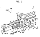
- Fig. 2 is an enlarged perspective view of a main part of an underrun protector mounting structure.
- Fig. 3 is a cross-sectional view along the line I-I in Fig. 2 .
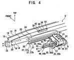
- Fig. 4 is an exploded perspective view of the underrun protector mounting structure.
- Fig. 5 is an exploded perspective view of the underrun protector mounting structure.
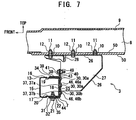
- Fig. 6 is an enlarged perspective view of a main part, showing a mounting state of a front underrun protector in the cab-over type truck having a relatively high ride height.
- Fig. 7 is a cross-sectional view along the line II-II in Fig. 6 .
- Note that "front” in the drawings represents the front of the vehicle and “top” in the drawings represents the top of the vehicle.
- a left-right direction in the following description means a left-right direction facing the direction of movement of the vehicle.
- a vehicle 1 is a cab-over type vehicle with a cab 2 generally positioned more anteriorly than an engine (not shown), and is equipped with an underrun protector mounting structure 3 at its front.
- the underrun protector mounting structure 3 includes: a chassis frame (vehicle body frame) 4 which is extended in a longitudinal direction on both sides in a lateral direction of the vehicle; a front underrun protector (underrun protector) 5 which is disposed at the front of the chassis frame 4 and extended in the lateral direction of the vehicle; a bracket 6 for fixing the front underrun protector 5 to the chassis frame 4; and a support part 7 interposed between the front underrun protector 5 and the bracket 6.
- the chassis frame 4 has an approximately squared U-shaped cross-section and includes a side wall part 8, an upper wall part 9 and a bottom wall part 50. Specifically, the upper wall part 9 and the bottom wall part 50 are extended, while facing each other, inward in the lateral direction of the vehicle respectively from both ends, in a vertical direction, of the side wall part 8. At predetermined positions on the bottom wall part 50, a plurality of bolt insertion holes 10 for mounting the bracket are formed, into which bolts 11 can be inserted. Above the bolt insertion holes 10 for mounting the bracket, nuts 12 which can be fitted to the bolts 11 are provided.
- the front underrun protector 5 has a protector piece 13 on the front side of the vehicle and a protector piece 14 on the rear side of the vehicle.
- Both of the protector pieces 13 and 14 are made of thin steel plates and formed to have an approximately squared U-shaped cross-section.
- the protector piece 13 has a side wall part 15, an upper wall part 16 and a bottom wall part 17. Specifically, the upper wall part 16 and the bottom wall part 17 are extended, while facing each other, toward the rear of the vehicle from both ends of the side wall part 15.
- the protector piece 14 has a side wall part 18, an upper wall part 19 and a bottom wall part 20.
- the upper wall part 19 and the bottom wall part 20 are extended, while facing each other, toward the front of the vehicle from both ends of the side wall part 18.
- a width of the side wall part 18 of the protector piece 14 in a vertical direction of the vehicle is set smaller than that of the side wall part 15 of the protector piece 13 in the vertical direction of the vehicle.
- bolt insertion holes (not shown) for mounting the support part are formed, into which bolts 21 can be inserted.
- nuts 22 which can be fitted to the bolts 21 are fixed by welding or the like.
- the protector pieces 13 and 14 are connected to each other by welding or the like. Thus, a closed cross-section is formed between the protector pieces 13 and 14. Moreover, caps 23 are attached to both ends of the front underrun protector 5.
- the bracket 6 is formed into an approximate box shape and has a peripheral wall part 26 having an approximately V-shaped cross-section, approximately plate-like side wall parts 27 and 27 disposed at lateral sides of the peripheral wall part 26, and a front wall part 28 having an approximately L-shaped cross-section and disposed at a front side of the side wall parts 27 and 27.
- the peripheral wall part 26 and the side wall parts 27, as well as the side wall parts 27 and the front wall part 28, are connected by welding or the like in a state where peripheral edges thereof come into contact with each other respectively.
- a plurality of concave rib receiving parts 30 are formed on the side wall parts 27 on the front underrun protector 5 side. Specifically, the rib receiving parts 30 can be fitted to a plurality of ribs 46; to be described later, of the support part 7.
- the plurality of rib receiving parts 30 have upper rib receiving parts 30a and lower rib receiving parts 30b.
- the upper and lower rib receiving parts 30a and 30b are formed into approximately the same shape and disposed facing each other in a state where the peripheral wall part 26 and the side wall parts 27 and 27 are connected to each other.
- a plurality of bolt insertion holes 61 for mounting the chassis frame are formed, into which the bolts 11 can be inserted.
- the bracket 6 is fastened and fixed to the chassis frame 4 in the following manner. Specifically, in a state where the upper surface of the peripheral wall part 26 of the bracket 6 comes into contact with a lower surface of the bottom wall part 50 of the chassis frame 4, the bolts 11 are inserted from below into the bolt insertion holes 10 for mounting the bracket in the chassis frame 4 and the bolt insertion holes 61 for mounting the chassis frame in the bracket 6, respectively. Thereafter, the bolts 11 are fitted to the nuts 12 attached to the chassis frame 4 and fastened.
- the support part 7 has a first plate part 31 with an approximately squared U-shaped cross-section, which is disposed on the front underrun protector 5 side and a second plate part 32 with an approximately L-shaped cross-section, which is disposed on the first plate part 31 on the bracket 6 side.
- the first plate part 31 is formed to be wider in the lateral direction of the vehicle than the second plate part 32.
- the first and second plate parts 31 and 32 are stacked in a leaf spring shape in the longitudinal direction of the vehicle.
- a width of the second plate part 32 in the lateral direction of the vehicle is set larger than that of the bracket 6 in the lateral direction of the vehicle on the front underrun protector 5.
- the first plate part 31 has a side wall part 33, an upper plate part 34 and a lower plate part 35. Specifically, the upper plate part 34 and the lower plate part 35 are extended, while facing each other, toward the front of the vehicle from both ends of the side wall part 33.
- a shape of an inner surface of the first plate part 31 is approximately the same as that of an outer surface of the protector piece 14 of the front underrun protector 5.
- a plurality of protrusions 37 are formed, which are projected toward the second plate part 32 and extended along the lateral direction of the vehicle.
- the plurality of protrusions 37 include an upper protrusion 37a and a lower protrusion 37b.
- the upper and lower protrusions 37a and 37b are formed to have approximately the same shape and provided approximately parallel to each other in the vertical direction of the vehicle with a space therebetween.
- bolt insertion holes (not shown) for mounting the front underrun protector are formed, into which the bolts 21 can be inserted.
- a supporting piece 38 is connected, by welding or the like, to the upper plate part 34 of the first plate part 31.
- This supporting piece 38 is formed to have an approximately L-shaped cross-section and has a bottom wall part 39 and a side wall part 40. Specifically, the bottom wall part 39 comes into contact with the upper plate part 34 of the first plate part 31, and the side wall part 40 is extended so as to be bent upward from an end of the bottom wall part 39 on the bracket 6 side.
- bolt insertion holes 42 for mounting the second plate part are formed, into which bolts 41 can be inserted.
- the second plate part 32 has a side wall part 43 and an extended part 44 which is extended so as to be bent toward the front underrun protector 5 from a lower end of the side wall part 43.
- a plurality of ribs 46 are formed, which are projected toward the bracket 6 and extended along the lateral direction of the vehicle.
- the plurality of ribs 46 include the upper rib 46a and the lower rib 46b.
- These upper and lower ribs 46a and 46b are formed to have approximately the same shape and provided approximately parallel to each other in the vertical direction of the vehicle with a space therebetween, at positions corresponding to the upper and lower rib receiving parts 30a and 30b of the bracket 6.
- convex outer surfaces of the upper and lower ribs 46a and 46b are formed into a shape where these ribs 46a and 46b can be fitted to the plurality of rib receiving parts 30.
- bolt insertion holes 47 for mounting the front underrun protector 5 are formed, into which the bolts 21 can be inserted.
- bolt insertion holes 48 for mounting the supporting piece 38 are formed, into which the bolts 41 can be inserted.
- the second plate part 32 is allowed to come into contact with the bracket 6 by fitting the upper and lower ribs 46a and 46b of the second plate part 32 to the upper and lower rib receiving parts 30a and 30b of the bracket 6, respectively. Thereafter, the bracket 6 and the second plate part 32 are connected to each other by welding, for example, a contact spot between the bracket 6 and the second plate part 32. Subsequently, an assembly thus obtained is fixed at a predetermined position on the chassis frame 4.
- the inner surface of the first plate part 31 is fitted to the outer surface of the front underrun protector 5. Moreover, the first plate part 31 is fixed, by welding, for example, to the front underrun protector 5 at a position where the bolt insertion holes formed in the front underrun protector 5 (the holes for mounting the support part), and the bolt insertion holes formed in the first plate part 31 (the holes for mounting the front underrun protector 5), are aligned with each other. Thereafter, the supporting piece 38 is fixed to the upper plate part 34 of the first plate part 31 by welding or the like at a position corresponding to the second plate part 32 fixed to the bracket 6.
- the front underrun protector 5 is placed on an upper surface of the extended part 44 of the second plate part 32 fixed to the bracket 6.
- the upper and lower protrusions 37a and 37b of the first plate part 31 fixed to the front underrun protector 5 are fitted to the upper and lower ribs 46a and 46b of the second plate part 32 fixed to the bracket 6, respectively.
- the bolts 41 are inserted from the front underrun protector 5 side into the bolt insertion holes 42 in the supporting piece 38 (the holes for mounting the second plate part) and into the bolt insertion holes 48 in the second plate part 3.2 (the holes for mounting the supporting piece), respectively.
- nuts 49 are fitted and fastened to the bolts from the bracket 6 side (see Fig. 4 ).
- the bolts 21 are inserted from below into the bolt insertion holes 47 in the second plate part 32 (the holes for mounting the front underrun protector), into the bolt insertion holes in the first plate part 31 (the holes for mounting the front underrun protector), and into the bolt insertion holes in the front underrun protector 5 (the holes for mounting the support part), respectively. Thereafter, the bolts 21 are fitted and fastened to the nuts 22 attached to the front underrun protector 5.
- the front underrun protector 5 is fixed to the chassis frame 4.
- the underrun protector mounting structure 3 of the present invention in the case where the underrun protector mounting structure 3 of the present invention is adopted in a vehicle (not shown) having a relatively high ride height due to a tire size or the like, first, the second plate part 32 and the bracket 6 are allowed to come into contact with each other by fitting the lower rib receiving part 30b of the bracket 6 and the upper rib 46a of the second plate part 32 to each other. Thereafter, the bracket 6 and the second plate part 32 are connected to each other by welding, for example, a contact spot between the bracket 6 and the second plate part 32. Next, the first plate part 31 fixed to the front underrun protector 5 and the second plate part 32 fixed to the bracket 6 are joined to each other. Thus, a mounting position of the front underrun protector 5 can be lowered to a predetermined height from the ground.
- the support part 7 is attached to a predetermined position on the bracket 6 by fitting the ribs 46 to the rib receiving parts 30, and then the front underrun protector 5 is attached to the support part 7.
- the front underrun protector 5 can be positioned relative to the bracket 6. Therefore, compared with the case where the heavy front underrun protector 5 is directly attached to the bracket 6, positioning of the front underrun protector 5 can be easily performed. Moreover, since no tools or the like are required for the positioning, efficient mounting of the front underrun protector 5 can be surely performed.
- the upper and lower rib receiving parts 30a and 30b which can be fitted to the upper and lower ribs 46a and 46b of the support part 7 are formed approximately parallel to each other in the vertical direction of the vehicle with a space therebetween.
- a mounting height of the front underrun protector 5 can be freely selected. Therefore, it is possible to use the same front underrun protector 5 for a plurality of vehicles having different ground clearances, and to adjust the mounting height of the front underrun protector.
- versatility can be improved and parts-sharing can be achieved.
- the ribs 46 are formed in the support part 7 that is separate from the front underrun protector 5, it is not required to form the ribs 46 in the front underrun protector 5 itself. Therefore, the existing front underrun protector 5 having no ribs 46 can be used. Thus, the cost required for formation of the front underrun protector 5 can be reduced.
- the second plate part 32 is attached to a predetermined position on the bracket 6 by fitting the ribs 46 to the rib receiving parts 30, and then the first plate part 31 and the front underrun protector 5 is attached to the second plate part 32.
- the first plate part 31 and the front underrun protector 5 can be previously and temporarily retained on the upper surface of the extended part 44. Therefore, compared with the case where the heavy front underrun protector 5 is directly attached to the bracket 6, positioning of the front underrun protector 5 can be easily performed.
- the first plate part 31 can be attached to a predetermined position on the second plate part 32 by fitting the convex outer surfaces of the protrusions 37 of the first plate part 31 to the concave inner surfaces of the ribs 46 of the second plate part 32.
- both of the first and second plate parts 31 and 32 are separate from the front underrun protector 5 and the bracket 6.
- the protrusions 37 and the ribs 46 can be set to have shapes that allow the both parts to be easily fitted to each other.
- the first plate part 31 is attached to the heavy front underrun protector 5, it is possible to easily perform positioning in joining the first plate part 31 to the second plate part 32. Moreover, the first and second plate parts 31 and 32 are joined to each other in a surface-contact state. Thus, the first and second plate parts 31 and 32 can be firmly fixed to each other. Consequently, a joint state of the front underrun protector 5 and the bracket 6 can be surely maintained.
- the first and second plate parts 31 and 32 are disposed in a stacked state.
- a substantial thickness of a portion of the front underrun protector 5, the portion being in contact with the support part 7, is increased by thicknesses of the first and second plate parts 31 and 32. Therefore, rigidity and strength of the front underrun protector 5 can be improved.
- the protrusions 37 and the ribs 46 are provided on the approximately plate-like first and second plate parts 31 and 32, respectively, so as to be extended along the lateral direction of the vehicle.
- the protrusions 37 and the ribs 46 are fitted to each other across a relatively wide area.
- the first and second plate parts 31 and 32 are members lighter than the front underrun protector 5 and the bracket 6.
- the first and second plate parts 31 and 32 can be easily attached to the front underrun protector 5 and the bracket 6, respectively.
- the protrusions 37 of the first plate part 31 and the ribs 46 of the second plate part 32 can be easily fitted to each other. Thus, extensively efficient mounting of the front underrun protector 5 can be performed.
- the support part 7 disposed on the front underrun protector 5 on the bracket 6 side is arranged so as to be projected from the both ends of the bracket 6 in the lateral direction of the vehicle.
- a portion of the front underrun protector 5, the portion on which most of the impact load acts in collision, in other words, a portion supported by the bracket 6 is reinforced by the support part 7.
- occurrence of excessive stress in this portion can be surely suppressed. Therefore, local bending of the front underrun protector 5 can be effectively suppressed.
- the rigidity and strength of the front underrun protector 5 as a whole can be improved.
- the support part 7 is separate from the front underrun protector 5.
- a thickness of the support part 7 and an overall length thereof in the lateral direction of the vehicle can be freely set to dimensions that can withstand the impact load. Therefore, the rigidity and strength of the front underrun protector 5 can be surely improved while minimizing the increase in weight.
- the upper and lower ribs 46a and 46b are formed in the support part 7, the mounting height of the front underrun protector 5 can be freely selected by selecting any of the upper and lower ribs 46a and 46b. Specifically, compared with the case where only one rib 46 is provided, a scope of selection of the mounting height of the front underrun protector 5 is expanded. Thus, a structure with further improved versatility can be achieved.
- the rigidity and strength of the front underrun protector 5 can be further improved.
- the underrun protector mounting structure 3 is applied to the front underrun protector 5 disposed at the front of the vehicle 1. Meanwhile, as shown in Fig. 8 , the underrun protector mounting structure 3 can also be applied to a rear underrun protector disposed at the rear of the vehicle.
- the two plate-like members, the first and second plate parts 31 and 32, are used to form the support part 7
- three or more plate-like members may be used to form the support part.
- the rib receiving parts 30, the protrusions 37 and the ribs 46 are provided on the bracket 6, the first plate part 31 and the second plate part 32, respectively, at two spots on each part. However, those described above can also be provided at three or more spots.
- a mounting height of an underrun protector may be adjusted by providing a plurality of rib receiving parts 30 in a bracket 6 and providing only one rib 46 in a second plate part 32, which can be fitted to any of the rib receiving parts 30.
- no protrusions 37 may be provided in a first plate part 31 as shown in Fig. 10 .
- a first plate part 31 itself may be not provided.
- the underrun protector mounting structure of the present invention can be applied to vehicles having different ground clearances without impairing functions of the underrun protector.
Landscapes
- Engineering & Computer Science (AREA)
- Mechanical Engineering (AREA)
- Body Structure For Vehicles (AREA)
Claims (4)
- Structure de montage de dispositif anti-encastrement (3) d'un véhicule (1), comprenant :un châssis de carrosserie de véhicule (4) ;un dispositif anti-encastrement (5) qui est disposé à l'avant ou à l'arrière du châssis de carrosserie de véhicule (4) et qui s'étend dans un sens latéral du véhicule (1) ;un socle (6) pour la fixation du dispositif anti-encastrement (5) au châssis de carrosserie de véhicule (4) ;et une partie de support (7) placée entre le dispositif anti-encastrement (5) et le socle (6) de la structure de montage de dispositif anti-encastrement (3),étant précisé que la partie de support (7) a une nervure (46, 46a, 46b) qui dépasse vers le socle (6) et qui s'étend le long du sens latéral du véhicule (1),que le socle (6) a plusieurs parties de réception de nervure (30, 30a, 30b) qui sont formées approximativement parallèlement les unes par rapport aux autres dans un sens vertical du véhicule (1), avec un espace, à chaque fois, entre deux parties de réception de nervure (30,30a, 30b), chacune de ces parties pouvant être installée sur la nervure (46, 46a, 46b),qu'une hauteur de montage de la partie de support (7) par rapport au socle (6) est réglée grâce à la sélection de l'une des parties de réception de nervure (30, 30a, 30b) et à l'installation de la partie de réception de nervure (30, 30a, 30b) sélectionnée sur la partie de support (7), etque la partie de support (7) est conçue comme une partie séparée sur laquelle le dispositif anti-encastrement (5) peut être monté de manière amovible et qui peut être montée de manière amovible sur le socle (6).
- Structure de montage de dispositif anti-encastrement d'un véhicule (1) selon la revendication 1,
dans lequel la partie de support (7) a une première partie approximativement en forme de plaque (31) et une seconde partie approximativement en forme de plaque (32) qui est posée sur la première partie (31), côté socle,
la première partie en forme de plaque (31) a une saillie (37, 37a, 37b) qui dépasse vers la seconde partie en forme de plaque (32) et qui s'étend le long du sens latéral du véhicule (1), et
la seconde partie en forme de plaque (32) présente la nervure (46, 46a, 46b) et est posée sur la première partie en forme de plaque (31) dans une position dans laquelle une surface extérieure convexe de la saillie (37, 37a, 37b) est installée sur une surface intérieure concave de la nervure (46, 46a, 46b). - Structure de montage de dispositif anti-encastrement (3) d'un véhicule (1) selon l'une des revendications 1 et 2,
dans lequel une largeur de la partie de support (7) dans le sens latéral du véhicule (1) est prévue pour être supérieure à celle du socle (6) dans le sens latéral du véhicule (1), côté dispositif anti-encastrement. - Structure de montage de dispositif anti-encastrement (3) d'un véhicule (1) selon l'une quelconque des revendications 1 à 3,
dans lequel la partie de support (7) a plusieurs nervures (46, 46a, 46b) et
les nervures (46, 46a, 46b) sont disposées approximativement parallèlement les unes par rapport aux autres dans un sens vertical du véhicule (1), avec à chaque fois un espace entre deux nervures (46, 46a, 46b).
Applications Claiming Priority (2)
| Application Number | Priority Date | Filing Date | Title |
|---|---|---|---|
| JP2006005079A JP5035658B2 (ja) | 2006-01-12 | 2006-01-12 | 車両のアンダーランプロテクタ取付構造 |
| PCT/JP2006/321257 WO2007080687A1 (fr) | 2006-01-12 | 2006-10-25 | Structure de montage de dispositif anti-encastrement sur un véhicule |
Publications (3)
| Publication Number | Publication Date |
|---|---|
| EP1972505A1 EP1972505A1 (fr) | 2008-09-24 |
| EP1972505A4 EP1972505A4 (fr) | 2009-01-14 |
| EP1972505B1 true EP1972505B1 (fr) | 2010-05-12 |
Family
ID=38256101
Family Applications (1)
| Application Number | Title | Priority Date | Filing Date |
|---|---|---|---|
| EP06822234A Not-in-force EP1972505B1 (fr) | 2006-01-12 | 2006-10-25 | Structure de montage de dispositif anti-encastrement sur un vehicule |
Country Status (6)
| Country | Link |
|---|---|
| US (1) | US7900983B2 (fr) |
| EP (1) | EP1972505B1 (fr) |
| JP (1) | JP5035658B2 (fr) |
| CN (1) | CN101356076B (fr) |
| DE (1) | DE602006014306D1 (fr) |
| WO (1) | WO2007080687A1 (fr) |
Families Citing this family (28)
| Publication number | Priority date | Publication date | Assignee | Title |
|---|---|---|---|---|
| JP4029301B2 (ja) | 2006-01-13 | 2008-01-09 | いすゞ自動車株式会社 | 車両のアンダーランプロテクタ取付構造 |
| DE102008007368A1 (de) * | 2007-11-12 | 2009-05-14 | Bätzold & Wagner GmbH & Co. KG | Unterfahrschutzvorrichtung |
| JP2009120095A (ja) * | 2007-11-16 | 2009-06-04 | Takebe Tekkosho:Kk | アンダーラン・プロテクタ |
| MY185663A (en) * | 2010-11-19 | 2021-05-28 | Honda Motor Co Ltd | Vehicle body structure |
| EP2524842B1 (fr) * | 2011-05-17 | 2014-05-07 | Iveco Magirus AG | Dispositif de fixation pour plaque de revêtement |
| JP5427216B2 (ja) * | 2011-09-27 | 2014-02-26 | 本田技研工業株式会社 | 軽荷重吸収構造 |
| WO2013142818A1 (fr) * | 2012-03-23 | 2013-09-26 | Sapa Extrusions, Inc. | Protection anti-encastrement de semi-remorque |
| USD728447S1 (en) * | 2013-02-18 | 2015-05-05 | Sabic Global Technologies B.V. | Underrun protection component |
| USD731398S1 (en) * | 2013-02-18 | 2015-06-09 | Sabic Global Technologies B.V. | Underrun protection component |
| US8944207B2 (en) * | 2013-03-05 | 2015-02-03 | Paccar Inc | Mid-engine chassis |
| JP6163417B2 (ja) * | 2013-11-28 | 2017-07-12 | ダイムラー・アクチェンゲゼルシャフトDaimler AG | アンダランプロテクタの構造 |
| JP6356959B2 (ja) * | 2013-11-28 | 2018-07-11 | ダイムラー・アクチェンゲゼルシャフトDaimler AG | アンダランプロテクタの構造 |
| JP6243717B2 (ja) * | 2013-11-28 | 2017-12-06 | ダイムラー・アクチェンゲゼルシャフトDaimler AG | アンダランプロテクタの構造 |
| WO2015128832A2 (fr) * | 2014-02-28 | 2015-09-03 | Sabic Global Technologies B.V. | Dispositif de protection contre l'encastrement hybride |
| MX362751B (es) | 2014-03-11 | 2019-02-07 | Wabash National Lp | Protección de impacto posterior. |
| CN104590182A (zh) * | 2015-01-21 | 2015-05-06 | 柳州聚龙科技有限公司 | 卡车后防护栏装置 |
| US9783144B2 (en) | 2015-08-18 | 2017-10-10 | Sti Holdings, Inc. | Trailer with rear impact guard |
| CA2942098C (fr) | 2015-09-16 | 2022-03-01 | Wabash National, L.P. | Protecteur d'impact arriere |
| US9937885B2 (en) * | 2016-01-08 | 2018-04-10 | SportChassis, LLC | Front under-run protection device for medium duty truck |
| WO2018038210A1 (fr) * | 2016-08-26 | 2018-03-01 | 新日鐵住金株式会社 | Structure de support pour dispositif de protection anti-encastrement |
| JP6729195B2 (ja) * | 2016-08-31 | 2020-07-22 | いすゞ自動車株式会社 | 車両 |
| US10029733B1 (en) * | 2017-01-12 | 2018-07-24 | Nissan North America, Inc. | Vehicle body structure |
| US10369949B2 (en) | 2017-02-27 | 2019-08-06 | Sti Holdings, Inc. | Rear impact guard |
| US10710535B2 (en) | 2017-08-29 | 2020-07-14 | Wabash National, L.P. | Rear impact guard for a tank trailer |
| US10526017B2 (en) | 2018-04-30 | 2020-01-07 | Nissan North America, Inc. | Vehicle body structure |
| US10661833B2 (en) | 2018-06-29 | 2020-05-26 | Nissan North America, Inc. | Vehicle body structure |
| US11407449B2 (en) | 2020-02-24 | 2022-08-09 | Nissan North America, Inc. | Energy absorbing structure for vehicle frame |
| JP7740522B2 (ja) * | 2022-03-29 | 2025-09-17 | 三菱自動車工業株式会社 | 車両の後部構造 |
Family Cites Families (12)
| Publication number | Priority date | Publication date | Assignee | Title |
|---|---|---|---|---|
| GB2086811B (en) * | 1980-09-16 | 1984-07-25 | Ford Motor Co | Road vehicle underride guard assembly |
| US4616866A (en) * | 1983-12-30 | 1986-10-14 | Michael Ladney, Jr. | Vehicle bumper |
| JPS6277056U (fr) * | 1985-11-05 | 1987-05-16 | ||
| SE502966C2 (sv) * | 1992-12-21 | 1996-03-04 | Saab Automobile | Stötfångare för fordon |
| US5507546A (en) * | 1993-08-13 | 1996-04-16 | Holley; John D. | Underride protection bumper |
| JP3268424B2 (ja) * | 1996-03-27 | 2002-03-25 | 日産ディーゼル工業株式会社 | 車両のフロントアンダランプロテクタの取付構造 |
| JPH09263197A (ja) * | 1996-03-27 | 1997-10-07 | Nissan Diesel Motor Co Ltd | 車両のフロントアンダランプロテクタの取付構造 |
| DE19644220C1 (de) * | 1996-10-24 | 1997-12-18 | Daimler Benz Ag | Seitlicher Unterfahrschutz für Nutzfahrzeuge |
| US6116667A (en) * | 1998-01-09 | 2000-09-12 | Torcomian; Albert | Trailer underride crash guard |
| US6652010B1 (en) * | 1999-09-10 | 2003-11-25 | Great Dane Limited Partnership | Rear impact guard assembly for trailers |
| SE520644C2 (sv) * | 2001-04-03 | 2003-08-05 | Volvo Lastvagnar Ab | Arrangemang vid underkörningsskydd för fordon |
| US7086674B2 (en) * | 2004-12-08 | 2006-08-08 | Goertz Alan R | Underride protection bumper for a trailer |
-
2006
- 2006-01-12 JP JP2006005079A patent/JP5035658B2/ja not_active Expired - Lifetime
- 2006-10-25 EP EP06822234A patent/EP1972505B1/fr not_active Not-in-force
- 2006-10-25 US US12/160,251 patent/US7900983B2/en active Active
- 2006-10-25 CN CN2006800508224A patent/CN101356076B/zh not_active Expired - Fee Related
- 2006-10-25 DE DE602006014306T patent/DE602006014306D1/de active Active
- 2006-10-25 WO PCT/JP2006/321257 patent/WO2007080687A1/fr not_active Ceased
Also Published As
| Publication number | Publication date |
|---|---|
| US20090001768A1 (en) | 2009-01-01 |
| CN101356076A (zh) | 2009-01-28 |
| EP1972505A1 (fr) | 2008-09-24 |
| US7900983B2 (en) | 2011-03-08 |
| CN101356076B (zh) | 2011-09-28 |
| JP5035658B2 (ja) | 2012-09-26 |
| EP1972505A4 (fr) | 2009-01-14 |
| JP2007186051A (ja) | 2007-07-26 |
| WO2007080687A1 (fr) | 2007-07-19 |
| DE602006014306D1 (de) | 2010-06-24 |
Similar Documents
| Publication | Publication Date | Title |
|---|---|---|
| EP1972505B1 (fr) | Structure de montage de dispositif anti-encastrement sur un vehicule | |
| EP1972506B1 (fr) | Structure de montage de dispositif anti-encastrement sur un vehicule | |
| EP1336536B1 (fr) | Structure de pare-chocs pour automobile | |
| EP1902928B1 (fr) | Structure frontale d'un véhicule automobile | |
| JP4488047B2 (ja) | ランプ取付け構造 | |
| JP5102728B2 (ja) | 車両用サブフレーム構造 | |
| US8020925B2 (en) | Front structure of cab-over type vehicle | |
| US20120126576A1 (en) | Reinforced vehicle structure | |
| US7828374B2 (en) | Structure of the front part of a motor vehicle | |
| JP3927845B2 (ja) | 車両用バンパ支持構造 | |
| JP2008254681A (ja) | 自動車のフェンダパネル支持構造 | |
| JP5070010B2 (ja) | 車両用のシャシフレーム構造 | |
| JP4479550B2 (ja) | エンジンアンダカバー取付構造 | |
| US5346275A (en) | Rear end of a vehicle body | |
| JP2005263114A (ja) | 自動車の後部車体構造 | |
| EP1669276B1 (fr) | Structure de support d'un véhicule avec dispositif pour la restriction du mouvement du plancher en cas de collision | |
| JP3947916B2 (ja) | プロテクタ部材の取付構造 | |
| KR101399334B1 (ko) | 차량용 범퍼빔 유닛 | |
| JP4106935B2 (ja) | 自動車の前部車体構造 | |
| US20240042955A1 (en) | Underrun Protector | |
| KR100256541B1 (ko) | 자동차의 리어범퍼 부착용 범퍼스테이 | |
| JP2006056404A (ja) | アンダーランプロテクタ構造 | |
| JP5150168B2 (ja) | 車両のロアメンバ構造 | |
| JP2005262983A (ja) | アンダーランプロテクタの取付構造 | |
| CN121469473A (zh) | 一种可拆卸防滚架总成及车身 |
Legal Events
| Date | Code | Title | Description |
|---|---|---|---|
| PUAI | Public reference made under article 153(3) epc to a published international application that has entered the european phase |
Free format text: ORIGINAL CODE: 0009012 |
|
| 17P | Request for examination filed |
Effective date: 20080709 |
|
| AK | Designated contracting states |
Kind code of ref document: A1 Designated state(s): DE FR GB IT |
|
| A4 | Supplementary search report drawn up and despatched |
Effective date: 20081215 |
|
| DAX | Request for extension of the european patent (deleted) | ||
| RBV | Designated contracting states (corrected) |
Designated state(s): DE FR GB IT |
|
| 17Q | First examination report despatched |
Effective date: 20090324 |
|
| GRAP | Despatch of communication of intention to grant a patent |
Free format text: ORIGINAL CODE: EPIDOSNIGR1 |
|
| GRAS | Grant fee paid |
Free format text: ORIGINAL CODE: EPIDOSNIGR3 |
|
| GRAA | (expected) grant |
Free format text: ORIGINAL CODE: 0009210 |
|
| AK | Designated contracting states |
Kind code of ref document: B1 Designated state(s): DE FR GB IT |
|
| REG | Reference to a national code |
Ref country code: GB Ref legal event code: FG4D |
|
| REF | Corresponds to: |
Ref document number: 602006014306 Country of ref document: DE Date of ref document: 20100624 Kind code of ref document: P |
|
| PLBE | No opposition filed within time limit |
Free format text: ORIGINAL CODE: 0009261 |
|
| STAA | Information on the status of an ep patent application or granted ep patent |
Free format text: STATUS: NO OPPOSITION FILED WITHIN TIME LIMIT |
|
| PGFP | Annual fee paid to national office [announced via postgrant information from national office to epo] |
Ref country code: IT Payment date: 20101025 Year of fee payment: 5 |
|
| 26N | No opposition filed |
Effective date: 20110215 |
|
| REG | Reference to a national code |
Ref country code: DE Ref legal event code: R097 Ref document number: 602006014306 Country of ref document: DE Effective date: 20110214 |
|
| PG25 | Lapsed in a contracting state [announced via postgrant information from national office to epo] |
Ref country code: IT Free format text: LAPSE BECAUSE OF NON-PAYMENT OF DUE FEES Effective date: 20111025 |
|
| PGFP | Annual fee paid to national office [announced via postgrant information from national office to epo] |
Ref country code: FR Payment date: 20121018 Year of fee payment: 7 Ref country code: DE Payment date: 20121017 Year of fee payment: 7 |
|
| PGFP | Annual fee paid to national office [announced via postgrant information from national office to epo] |
Ref country code: GB Payment date: 20121024 Year of fee payment: 7 |
|
| GBPC | Gb: european patent ceased through non-payment of renewal fee |
Effective date: 20131025 |
|
| REG | Reference to a national code |
Ref country code: DE Ref legal event code: R119 Ref document number: 602006014306 Country of ref document: DE Effective date: 20140501 |
|
| PG25 | Lapsed in a contracting state [announced via postgrant information from national office to epo] |
Ref country code: GB Free format text: LAPSE BECAUSE OF NON-PAYMENT OF DUE FEES Effective date: 20131025 |
|
| REG | Reference to a national code |
Ref country code: FR Ref legal event code: ST Effective date: 20140630 |
|
| PG25 | Lapsed in a contracting state [announced via postgrant information from national office to epo] |
Ref country code: DE Free format text: LAPSE BECAUSE OF NON-PAYMENT OF DUE FEES Effective date: 20140501 Ref country code: FR Free format text: LAPSE BECAUSE OF NON-PAYMENT OF DUE FEES Effective date: 20131031 |