EP1973007A1 - Bilderzeugungsvorrichtung - Google Patents
Bilderzeugungsvorrichtung Download PDFInfo
- Publication number
- EP1973007A1 EP1973007A1 EP08150207A EP08150207A EP1973007A1 EP 1973007 A1 EP1973007 A1 EP 1973007A1 EP 08150207 A EP08150207 A EP 08150207A EP 08150207 A EP08150207 A EP 08150207A EP 1973007 A1 EP1973007 A1 EP 1973007A1
- Authority
- EP
- European Patent Office
- Prior art keywords
- warm
- image forming
- fixing
- recording material
- mode
- Prior art date
- Legal status (The legal status is an assumption and is not a legal conclusion. Google has not performed a legal analysis and makes no representation as to the accuracy of the status listed.)
- Withdrawn
Links
Images




Classifications
-
- G—PHYSICS
- G03—PHOTOGRAPHY; CINEMATOGRAPHY; ANALOGOUS TECHNIQUES USING WAVES OTHER THAN OPTICAL WAVES; ELECTROGRAPHY; HOLOGRAPHY
- G03G—ELECTROGRAPHY; ELECTROPHOTOGRAPHY; MAGNETOGRAPHY
- G03G15/00—Apparatus for electrographic processes using a charge pattern
- G03G15/50—Machine control of apparatus for electrographic processes using a charge pattern, e.g. regulating differents parts of the machine, multimode copiers, microprocessor control
- G03G15/5016—User-machine interface; Display panels; Control console
- G03G15/502—User-machine interface; Display panels; Control console relating to the structure of the control menu, e.g. pop-up menus, help screens
-
- G—PHYSICS
- G03—PHOTOGRAPHY; CINEMATOGRAPHY; ANALOGOUS TECHNIQUES USING WAVES OTHER THAN OPTICAL WAVES; ELECTROGRAPHY; HOLOGRAPHY
- G03G—ELECTROGRAPHY; ELECTROPHOTOGRAPHY; MAGNETOGRAPHY
- G03G15/00—Apparatus for electrographic processes using a charge pattern
- G03G15/20—Apparatus for electrographic processes using a charge pattern for fixing, e.g. by using heat
- G03G15/2003—Apparatus for electrographic processes using a charge pattern for fixing, e.g. by using heat using heat
- G03G15/2014—Apparatus for electrographic processes using a charge pattern for fixing, e.g. by using heat using heat using contact heat
- G03G15/2039—Apparatus for electrographic processes using a charge pattern for fixing, e.g. by using heat using heat using contact heat with means for controlling the fixing temperature
-
- G—PHYSICS
- G03—PHOTOGRAPHY; CINEMATOGRAPHY; ANALOGOUS TECHNIQUES USING WAVES OTHER THAN OPTICAL WAVES; ELECTROGRAPHY; HOLOGRAPHY
- G03G—ELECTROGRAPHY; ELECTROPHOTOGRAPHY; MAGNETOGRAPHY
- G03G15/00—Apparatus for electrographic processes using a charge pattern
- G03G15/65—Apparatus which relate to the handling of copy material
- G03G15/6588—Apparatus which relate to the handling of copy material characterised by the copy material, e.g. postcards, large copies, multi-layered materials, coloured sheet material
- G03G15/6594—Apparatus which relate to the handling of copy material characterised by the copy material, e.g. postcards, large copies, multi-layered materials, coloured sheet material characterised by the format or the thickness, e.g. endless forms
-
- G—PHYSICS
- G03—PHOTOGRAPHY; CINEMATOGRAPHY; ANALOGOUS TECHNIQUES USING WAVES OTHER THAN OPTICAL WAVES; ELECTROGRAPHY; HOLOGRAPHY
- G03G—ELECTROGRAPHY; ELECTROPHOTOGRAPHY; MAGNETOGRAPHY
- G03G2215/00—Apparatus for electrophotographic processes
- G03G2215/00362—Apparatus for electrophotographic processes relating to the copy medium handling
- G03G2215/00367—The feeding path segment where particular handling of the copy medium occurs, segments being adjacent and non-overlapping. Each segment is identified by the most downstream point in the segment, so that for instance the segment labelled "Fixing device" is referring to the path between the "Transfer device" and the "Fixing device"
- G03G2215/00371—General use over the entire feeding path
-
- G—PHYSICS
- G03—PHOTOGRAPHY; CINEMATOGRAPHY; ANALOGOUS TECHNIQUES USING WAVES OTHER THAN OPTICAL WAVES; ELECTROGRAPHY; HOLOGRAPHY
- G03G—ELECTROGRAPHY; ELECTROPHOTOGRAPHY; MAGNETOGRAPHY
- G03G2215/00—Apparatus for electrophotographic processes
- G03G2215/00362—Apparatus for electrophotographic processes relating to the copy medium handling
- G03G2215/00443—Copy medium
- G03G2215/00451—Paper
- G03G2215/00476—Non-standard property
- G03G2215/00481—Thick
-
- G—PHYSICS
- G03—PHOTOGRAPHY; CINEMATOGRAPHY; ANALOGOUS TECHNIQUES USING WAVES OTHER THAN OPTICAL WAVES; ELECTROGRAPHY; HOLOGRAPHY
- G03G—ELECTROGRAPHY; ELECTROPHOTOGRAPHY; MAGNETOGRAPHY
- G03G2215/00—Apparatus for electrophotographic processes
- G03G2215/00362—Apparatus for electrophotographic processes relating to the copy medium handling
- G03G2215/00535—Stable handling of copy medium
- G03G2215/00717—Detection of physical properties
- G03G2215/00742—Detection of physical properties of sheet weight
-
- G—PHYSICS
- G03—PHOTOGRAPHY; CINEMATOGRAPHY; ANALOGOUS TECHNIQUES USING WAVES OTHER THAN OPTICAL WAVES; ELECTROGRAPHY; HOLOGRAPHY
- G03G—ELECTROGRAPHY; ELECTROPHOTOGRAPHY; MAGNETOGRAPHY
- G03G2215/00—Apparatus for electrophotographic processes
- G03G2215/00362—Apparatus for electrophotographic processes relating to the copy medium handling
- G03G2215/00919—Special copy medium handling apparatus
- G03G2215/00949—Copy material feeding speed switched according to current mode of the apparatus, e.g. colour mode
Definitions
- the present invention relates to an image forming apparatus, and in particular, to an image forming apparatus wherein an image is fixed on a recording material through heat fixing.
- a waiting time called a warm-up time that covers a period of time from the moment when a heater of the fixing device is turned on to the moment when a temperature of the heater arrives at a level for fixing, and there have been made various suggestions for shortening the warm-up time, because users wish to have a shorter waiting time.
- Patent Document 1 discloses a technology to lower the temperature capable of fixing to shorten the warm-up time, by lowering a speed for conveying a recording material in the fixing device, that is, a fixing speed.
- the amount of heat reduced by the reduction of the fixing temperature is compensated with the reduction of the fixing speed, resulting in advantages that a problem of insufficient fixing is mitigated considerably, and an effect of reduction of the warm-up time is obtained sufficiently.
- the device of the Patent Document 1 has the following problems.
- any of the conventional technology for shortening a warm-up time is not sufficient, and it has a problem, in particular, that the reduction of the warm-up time desired by a user cannot be attained.
- An objective of the invention is to provide an image forming apparatus wherein quick output satisfying user's needs is possible when a user desires that a print is outputted within a short period of time after the user presses a copy button, and sufficient fixing ability is secured.
- An image forming apparatus having therein an image forming section that forms an image on a recording material and a fixing device that conducts heat fixing of the image on the recording material, wherein there are provided a control section that controls a recording material conveyance speed and controls a warm-up completion temperature in the aforesaid fixing device and a quick output mode setting section wherein a quick output mode to shorten a warm-up time to conduct image forming process is set by user's operations, and the aforesaid control section sets the aforesaid recording material conveyance speed to the first speed at the first warm-up completion temperature when the aforesaid quick output mode is not set by the aforesaid quick output mode setting section, and sets the aforesaid recording material conveyance speed to the second speed that is lower than the first speed at the second warm-up completion temperature that is lower than the first warm-up completion temperature when the aforesaid quick output mode is set by the aforesaid quick output mode setting section.
- Fig. 2 is a structural diagram of an image forming apparatus relating to the embodiment of the invention.
- Image forming apparatus A is one called a tandem type color image forming apparatus that is composed of plural sets of image forming sections 10Y, 10M, 10C and 10K, belt-shaped intermediate transfer body 6, sheet-feeding section 20 and fixing device 30.
- Image reading apparatus SC is installed in the upper portion of image forming apparatus A. Images of a document placed on a document table are subjected to scanning exposure by an optical system of a document image scanning exposure section of the image reading apparatus SC, to be read in a line image sensor. Analog signals converted photoelectrically by the line image sensor are subjected to analog processing, A/D conversion, shading correction and image compression processing in the image processing section, to be inputted in exposure sections 3Y, 3M, 3C and 3K.
- An image forming apparatus that forms images on recording material P is composed of image forming sections 10Y, 10M, 10C and 10K, intermediate transfer body 70 and of secondary transfer device 5A.
- the image forming section 10Y that forms images in yellow (Y) color has charging unit 2Y, exposure unit 3Y, developing unit 4Y and cleaning unit 6Y which are arranged on a circumference of photoconductor drum 1Y representing an image carrier.
- the image forming section 10M that forms images in magenta (M) color has photoconductor drum 1M representing an image carrier, charging unit 2M, exposure unit 3M, developing unit 4M and cleaning unit 6M.
- the image forming section 10C that forms images in cyan (C) color has photoconductor drum 1C representing an image carrier, charging unit 2C, exposure unit 3C, developing unit 4C and cleaning unit 6C.
- the image forming section 10K that forms images in black (K) color has photoconductor drum 1K representing an image carrier, charging unit 2K, exposure unit 3K, developing unit 4K and cleaning unit 6K.
- a latent image forming section is composed of charging unit 2Y and exposure unit 3Y, charging unit 2M and exposure unit 3M, charging unit 2C and exposure unit 3C and of charging unit 2K and exposure unit 3K.
- the symbols 4Y, 4M, 4C and 4K represent developing units housing two-component developers which are composed respectively of yellow (Y) small particle size toner and carrier, magenta (M) small particle size toner and carrier, cyan (C) small particle size toner and carrier and black (K) small particle size toner and carrier.
- the intermediate transfer body 70 is wound around a plurality of rollers 71 - 74 to be supported rotatably.
- Images in respective colors formed respectively by the image forming sections 10Y, 10M, 10C and 10K are transferred onto rotating intermediate transfer body 70 in sequence respectively by primary transfer devices 5Y, 5M, 5C and 5K, thus, a composite color image is formed.
- the image forming sections 10Y, 10M, 10C and 10K, the intermediate transfer body 70 and secondary transfer device 5A constitute an image forming section that forms images on recording material P.
- Recording sheet P loaded in sheet-feeding cassette 20 is fed by sheet-feeding section (first sheet-feeding section) 21, and is conveyed to secondary transfer device 5A through sheet-feeding rollers 22A, 22B, 22C and 22D and through registration roller (second sheet-feeding section) 23, thus, a color image is transferred onto recording sheet P.
- sheet-feeding cassettes 20 in three stages arranged in the vertical direction below image forming apparatus A are of the same structure substantially, and three sheet-feeding sections 21 are also of the same structure substantially.
- a color toner image (or a toner image) on recording sheet P receives heat and pressure to be fixed on the recording sheet P, which is interposed between sheet-ejection rollers 25 to be ejected on sheet-ejection tray 26 outside an apparatus.
- the fixing device 24 has fixing roller 24A wherein heater 24C composed of a halogen lamp is arranged and has pressure roller 24B that is in pressure contact with the fixing roller 24B, and recording material P is interposed between the fixing roller 24A and pressure roller 24B to be conveyed, and heating during the conveyance makes an unfixed toner image on the recording material P to be fixed.
- heater 24C composed of a halogen lamp
- pressure roller 24B that is in pressure contact with the fixing roller 24B
- recording material P is interposed between the fixing roller 24A and pressure roller 24B to be conveyed, and heating during the conveyance makes an unfixed toner image on the recording material P to be fixed.
- the symbol 24D represents a temperature sensor that detects a surface temperature of the fixing roller 24A.
- cleaning device 6A removes toner remaining on intermediate transfer body 70 from which the recording sheet P is curvature-separated after a color image is transferred onto the recording sheet P by secondary transfer device 5A.
- the intermediate transfer body 70 is wound around a plurality of rollers 71 - 74 to conduct cyclic movement in the direction of the arrow.
- Fig. 3 is a block diagram of a control system of the image forming apparatus shown in Fig. 2 .
- the symbol OP represents an operation display section, and it has sheet type setting button PS representing a recording material type setting section that can set the sheet type by distinguishing types of recording materials, for example, by distinguishing regular paper from thick paper which is thicker than regular paper, quick output button QB representing a quick output setting section and image forming mode setting button MB representing a mode setting section.
- the quick output setting button QB is a button that is operated when a user desires quick output, that is, desires that a print is finished within a short period of time after a copy button is pressed.
- the symbol 24D represents a temperature sensor that detects a surface temperature of the fixing roller 24A as shown in Fig. 2 , and it is composed of a thermistor.
- the symbol 24C represents a heater that is arranged inside fixing roller 24 and heats fixing roller 24A up to the temperature capable of fixing as shown in Fig. 2
- 24E represents a motor that drives the fixing roller 24A.
- Control section CR controls heater 24C and motor 24E based on signals from recording material type setting section PS, quick output button QB, image forming mode setting button MB and temperature sensor 24D, as described later.
- control section CR operates motor 24E at a prescribed speed based on setting information in sheet type setting button PS and in image forming mode setting button MB, and controls a surface temperature of fixing roller 24E to be a prescribed fixing temperature based on output of temperature sensor 24D, to fix a toner image.
- Table 1 Fixing temperature Regular paper Linear speed Thick paper Linear speed Monochrome image Color image Monochrome image Color image 140°C - 125mm/s - - - 150°C - 140mm/s 125mm/s - - 160°C - 250mm/s 140mm/s 125mm/s - 170°C - 300mm/s 250mm/s 140mm/s 125mm/s
- a lower limit of the fixing temperature namely, a fixing-feasible temperature is made to be lower.
- a fixing-feasible temperature needs to be higher because the amount of heat necessary for fixing is larger than in the case of a monochrome mode.
- the amount of heat necessary for fixing is larger than that for regular paper, therefore, the fixing-feasible temperature is made to be higher and the fixing speed needs to be lowered.
- the fixing-feasible temperature is a target temperature for finishing a warm-up when conducting a warm-up. To be more specifuc, when the fixing temperature arrives at the fixing-feasible temperature, the warm-up is finished, and concurrently with a termination of the warm-up, image forming turns out to be possible.
- the fixing-feasible temperature is called also a warm-up completion temperature.
- warm-up completion temperatures t1 - t4 and fixing speeds v1 - v4 correspond to Table 1, and they have the following values; t1: 140°C, t2: 150°C, t3: 160°C and t4: 170°C and v1: 125 mm/s, v2: 140 mm/s, v3: 250 mm/s and v4: 300 mm/s.
- the fixing-feasible temperature is 140°C.
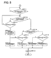
- FIG. 4 and Fig. 5 is a flow chart of a fixing control to control warm-up completion temperatures and fixing speeds in Embodiment 1 of the invention.
- recording material conveyance speed is set to the first speed at the first warm-up completion temperature, as described below. Further, when the quick output mode is set, the aforesaid recording material conveyance speed is set to the second speed that is lower than the first speed, at the second warm-up completion temperature that is lower than the first warm-up completion temperature.
- the fixing speed is set to the appropriate value, relating to a warm-up completion temperature, types of recording materials and distinction of a monochrome mode and a color mode.
- Total operations speeds in the image forming apparatus namely, linear speeds respectively for photoconductor drums 1Y, 1M, 1C and 1K, linear speeds of developing sleeves in developing units 4Y, 4M, 4C and 4K, a linear speed of intermediate transfer body 70 and a conveyance speed for recording material are set corresponding to the selected fixing speed.
- the operation speeds of the total image forming apparatus of this kind are called process speeds.
- the fixing control is started by power-on.
- This power-on represents power activation for a main switch or a return to an operation mode from a power-saving mode.
- Heater 24E of a fixing device is turned on by the power-on to start heating, and a period from this moment to the moment to arrive at the fixing-feasible temperature is warm-up time.
- STEP 1 a judgment is made whether a mode is a quick output mode or not.
- the symbol Y represents an occasion when a quick output mode button is pressed by an operator, and the symbol N represents an occasion when a quick output mode button is not pressed.
- the control in the case of N in a judgment in STEP 1 is shown in Fig. 4 .
- the fixing temperature is judged whether it has arrived at warm-up completion temperature t4 or not, and the warm-up is continued until the fixing temperature arrives at warm-up completion temperature t4.
- a mode is judged whether it is a monochrome mode or not (STEP3).
- a recording material used in STEP 4 is judged whether it is regular paper or not.
- fixing speed v1 is selected (STEP 6).
- the fixing temperature is judged whether it is less than warm-up completion temperature t1 or not, in STEP 21 in Fig. 5 .
- the fixing temperature is judged whether it has arrived at warm-up completion temperature t4 or not (STEP 22).
- an apparatus is constructed so that monochrome printing is conducted in the quick output mode. Accordingly, cautions to the effect that "In the quick output mode, monochrome copying or monochrome printing only is conducted. Therefore, a quick output button should not be used when color copying or color printing is desired.” are shown on a display or on a user manual.
- monochrome images are outputted in the quick output mode, even in the case of copies or prints based on color image data.
- a mode is judged whether it is a monochrome mode or not at STEP 26.
- Fig. 6 is a flow chart of fixing control in Embodiment 2 of the invention.
- control where a quick output button is not pressed is the same as that shown in Fig. 4 .
- the control up to STEP 22 is the same as that in Embodiment 1, and in the present embodiment, when the fixing temperature is judged not to have arrived at warm-up completion temperature t4 in the judgment at STEP 22, the sheet is judged whether it is regular paper or not in STEP 23.
- Embodiment 1 shown in Fig. 5 The present embodiment is the same as Embodiment 1 shown in Fig. 5 , except for STEP 23 and STEP 40.
- Each of STEP 23 and STEP 40 is a step for pressing a quick output button, selecting a monochrome mode, functioning only when using regular paper, and practicing the fixing control to start image forming after waiting the fixing temperature to rise to the necessary temperature, when a color mode is set and thick paper is used despite pressing of a quick output button.
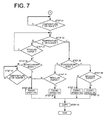
- Fig. 7 is a flow chart of fixing control in Embodiment 3 of the invention.
- control where a quick output button is not pressed is the same as that shown in Fig. 4 .
- Steps up to STEP 23 in fixing control of the present embodiment are the same as those in Embodiment 2 shown in Fig. 6 .
- fixing speed v1 is selected in STEP 29.
- the fixing speed by causing the fixing speed to be 125 mm/sec under the conditions of a quick output mode, using a regular paper and in a color mode, fixing at fixing temperature 150°C that is lower than 170°C is possible, thus, a warm-up time is shortened by an amount equivalent to a reduction of the fixing temperature.
- Fig. 8 is a flow chart of fixing control in Embodiment 4 of the invention.
- control where a quick output button is not pressed is the same as that shown in Fig. 4 .
- a mode is judged whether it is a monochrome mode or not in STEP 51.
- the fixing temperature is waited until it rises to warm-up completion temperature t1 (loop in STEP 52).
- fixing speed v1 is selected (STEP 54).
- fixing speed v2 is selected (STEP 56)
- fixing speed v3 is selected (STEP 58) and when the fixing temperature is warm-up completion temperature t4 or higher (Y in STEP 57)
- fixing speed v4 is selected.
- the fixing temperature is waited until it rises up to warm-up completion temperature t2 or higher (loop in STEP 60).
- fixing speed v1 is selected (STEP 62).
- fixing speed v2 is selected (STEP 64)
- fixing speed v3 is selected (STEP 65).
- a quick output mode is eliminated when thick paper is used, and fixing speed is controlled finely for each of a monochrome mode and a color mode when regular paper is used, thus, a warm-up time is shortened as far as possible to shorten waiting time.
- the fixing controls are different from each other depending on user's setting of quick output mode, and establishment of a guidance concerning setting of quick output mode is user-friendly, which is preferable.
- Fig. 9 is a flow chart of the guidance.
- the symbol M in STEP 70 represents the number of sets of copies.
- the symbol M0 represents a marginal number of sheets concerning reduction effects wherein an increase of time caused by a slowdown of the speed exceeds a reduction of a warm-up time.
- copy completion time is determined by the number of sets of copies and by the number of documents.
- message B of the guidance is displayed based on the number of copies and the number of documents.
- the message B is as follows.
Landscapes
- Physics & Mathematics (AREA)
- General Physics & Mathematics (AREA)
- Engineering & Computer Science (AREA)
- Human Computer Interaction (AREA)
- Microelectronics & Electronic Packaging (AREA)
- Fixing For Electrophotography (AREA)
- Control Or Security For Electrophotography (AREA)
Applications Claiming Priority (1)
| Application Number | Priority Date | Filing Date | Title |
|---|---|---|---|
| JP2007070302 | 2007-03-19 |
Publications (1)
| Publication Number | Publication Date |
|---|---|
| EP1973007A1 true EP1973007A1 (de) | 2008-09-24 |
Family
ID=39472556
Family Applications (1)
| Application Number | Title | Priority Date | Filing Date |
|---|---|---|---|
| EP08150207A Withdrawn EP1973007A1 (de) | 2007-03-19 | 2008-01-14 | Bilderzeugungsvorrichtung |
Country Status (3)
| Country | Link |
|---|---|
| US (1) | US7764890B2 (de) |
| EP (1) | EP1973007A1 (de) |
| JP (1) | JP5211774B2 (de) |
Families Citing this family (6)
| Publication number | Priority date | Publication date | Assignee | Title |
|---|---|---|---|---|
| KR101297709B1 (ko) | 2008-01-04 | 2013-08-22 | 삼성전자주식회사 | 화상형성장치 및 그 제어방법 |
| US8634736B2 (en) * | 2010-04-05 | 2014-01-21 | Kabushiki Kaisha Toshiba | Method and apparatus for fixing a toner image before a fixing unit reaches a ready temperature |
| US8731423B2 (en) * | 2011-01-19 | 2014-05-20 | Kabushiki Kaisha Toshiba | Image forming apparatus and control device and control method of fixing device |
| JP6039284B2 (ja) * | 2012-07-25 | 2016-12-07 | キヤノン株式会社 | 像加熱装置及び画像形成装置 |
| JP2016045465A (ja) * | 2014-08-26 | 2016-04-04 | 株式会社沖データ | 画像形成装置及び画像形成プログラム |
| JP2018120094A (ja) * | 2017-01-25 | 2018-08-02 | 株式会社東芝 | 画像形成装置 |
Citations (7)
| Publication number | Priority date | Publication date | Assignee | Title |
|---|---|---|---|---|
| JPS63228177A (ja) * | 1987-03-18 | 1988-09-22 | Canon Inc | 画像形成装置 |
| US4914476A (en) * | 1987-10-19 | 1990-04-03 | Ricoh Company, Ltd. | Device for displaying warm-up waiting time of image forming apparatus |
| JPH05142884A (ja) * | 1991-11-22 | 1993-06-11 | Mita Ind Co Ltd | 複写機 |
| US5905925A (en) * | 1996-12-04 | 1999-05-18 | Fuji Xerox Co., Ltd. | Image formation apparatus for changing operation conditions based on characteristics of the transfer material |
| JP2002132086A (ja) * | 2000-10-20 | 2002-05-09 | Kyocera Mita Corp | 画像形成装置 |
| US20050013626A1 (en) * | 2003-06-05 | 2005-01-20 | Naoki Satoh | Image forming apparatus, image forming method, and fixing unit |
| US20050135827A1 (en) * | 2003-12-19 | 2005-06-23 | Canon Kabushiki Kaisha | Image forming apparatus |
Family Cites Families (12)
| Publication number | Priority date | Publication date | Assignee | Title |
|---|---|---|---|---|
| JP3129466B2 (ja) * | 1991-01-31 | 2001-01-29 | 株式会社リコー | 電子事務機器の表示装置 |
| JP2001092300A (ja) * | 1999-09-20 | 2001-04-06 | Canon Inc | 定着装置および画像形成装置 |
| JP2001356616A (ja) * | 2000-06-14 | 2001-12-26 | Pfu Ltd | 電子写真装置 |
| US6381422B1 (en) * | 2000-07-31 | 2002-04-30 | Toshiba Tec Kabushiki Kaisha | Image forming apparatus for fine-adjusting a fixation speed of a development material in accordance with temperature control |
| JP2003066765A (ja) | 2001-08-28 | 2003-03-05 | Konica Corp | 画像形成装置 |
| JP4011895B2 (ja) * | 2001-11-22 | 2007-11-21 | キヤノン株式会社 | 画像形成装置 |
| JP2004271715A (ja) * | 2003-03-06 | 2004-09-30 | Kyocera Mita Corp | 画像形成装置 |
| JP2005003818A (ja) * | 2003-06-10 | 2005-01-06 | Casio Electronics Co Ltd | 画像形成装置 |
| JP2006243347A (ja) * | 2005-03-03 | 2006-09-14 | Canon Inc | 画像形成装置 |
| US7729628B2 (en) * | 2005-09-13 | 2010-06-01 | Canon Kabushiki Kaisha | Image heating apparatus including a transition temperature lower than a target low temperature |
| SG136862A1 (en) * | 2006-04-21 | 2007-11-29 | Oce Tech Bv | Variable speed printing |
| JP2008046552A (ja) * | 2006-08-21 | 2008-02-28 | Konica Minolta Business Technologies Inc | 画像形成装置 |
-
2008
- 2008-01-14 EP EP08150207A patent/EP1973007A1/de not_active Withdrawn
- 2008-01-16 US US12/014,983 patent/US7764890B2/en active Active
- 2008-03-14 JP JP2008065480A patent/JP5211774B2/ja not_active Expired - Fee Related
Patent Citations (7)
| Publication number | Priority date | Publication date | Assignee | Title |
|---|---|---|---|---|
| JPS63228177A (ja) * | 1987-03-18 | 1988-09-22 | Canon Inc | 画像形成装置 |
| US4914476A (en) * | 1987-10-19 | 1990-04-03 | Ricoh Company, Ltd. | Device for displaying warm-up waiting time of image forming apparatus |
| JPH05142884A (ja) * | 1991-11-22 | 1993-06-11 | Mita Ind Co Ltd | 複写機 |
| US5905925A (en) * | 1996-12-04 | 1999-05-18 | Fuji Xerox Co., Ltd. | Image formation apparatus for changing operation conditions based on characteristics of the transfer material |
| JP2002132086A (ja) * | 2000-10-20 | 2002-05-09 | Kyocera Mita Corp | 画像形成装置 |
| US20050013626A1 (en) * | 2003-06-05 | 2005-01-20 | Naoki Satoh | Image forming apparatus, image forming method, and fixing unit |
| US20050135827A1 (en) * | 2003-12-19 | 2005-06-23 | Canon Kabushiki Kaisha | Image forming apparatus |
Also Published As
| Publication number | Publication date |
|---|---|
| JP2008262184A (ja) | 2008-10-30 |
| US7764890B2 (en) | 2010-07-27 |
| JP5211774B2 (ja) | 2013-06-12 |
| US20080232834A1 (en) | 2008-09-25 |
Similar Documents
| Publication | Publication Date | Title |
|---|---|---|
| JP5498977B2 (ja) | 画像形成装置 | |
| EP2911009B1 (de) | Bilderzeugungsvorrichtung | |
| KR100559804B1 (ko) | 화상 형성 장치 | |
| US7764890B2 (en) | Image forming apparatus with quick output mode setting section | |
| US7593658B2 (en) | Image forming apparatus | |
| JP2008064984A (ja) | 画像形成装置 | |
| JP2007035606A (ja) | 加熱装置、定着装置及び画像形成装置 | |
| JP2003066765A (ja) | 画像形成装置 | |
| JP2011242598A (ja) | 画像形成装置 | |
| JP2002132086A (ja) | 画像形成装置 | |
| CN109283810B (zh) | 图像形成装置 | |
| JP2012098654A (ja) | 複連式画像形成装置 | |
| JP2006072236A (ja) | 画像形成装置及びその制御方法 | |
| JP2005043821A (ja) | 画像形成装置 | |
| US7447451B2 (en) | Image printing apparatus with fixing device | |
| JPH10274903A (ja) | 定着器と定着器の温度制御方法と画像形成装置 | |
| JP6929257B2 (ja) | 画像形成装置及び制御装置 | |
| JP2007240962A (ja) | 画像形成装置 | |
| JP2012022026A (ja) | 画像形成装置 | |
| JP4958210B2 (ja) | 定着制御方法,装置および画像形成装置 | |
| JP2000147966A (ja) | コピーサービスを行う画像形成装置 | |
| JP2008008936A (ja) | カラー画像形成装置 | |
| JP4574485B2 (ja) | 定着装置、画像形成装置および定着装置の制御方法 | |
| JP4122780B2 (ja) | 画像形成装置 | |
| JP2001315985A (ja) | 用紙搬送装置及び画像読取装置 |
Legal Events
| Date | Code | Title | Description |
|---|---|---|---|
| PUAI | Public reference made under article 153(3) epc to a published international application that has entered the european phase |
Free format text: ORIGINAL CODE: 0009012 |
|
| AK | Designated contracting states |
Kind code of ref document: A1 Designated state(s): AT BE BG CH CY CZ DE DK EE ES FI FR GB GR HR HU IE IS IT LI LT LU LV MC MT NL NO PL PT RO SE SI SK TR |
|
| AX | Request for extension of the european patent |
Extension state: AL BA MK RS |
|
| 17P | Request for examination filed |
Effective date: 20090316 |
|
| 17Q | First examination report despatched |
Effective date: 20090423 |
|
| AKX | Designation fees paid |
Designated state(s): DE FR GB |
|
| STAA | Information on the status of an ep patent application or granted ep patent |
Free format text: STATUS: THE APPLICATION IS DEEMED TO BE WITHDRAWN |
|
| 18D | Application deemed to be withdrawn |
Effective date: 20090904 |