EP1975558A2 - Vorrichtung und Verfahren zur Bilderkennung - Google Patents
Vorrichtung und Verfahren zur Bilderkennung Download PDFInfo
- Publication number
- EP1975558A2 EP1975558A2 EP08004629A EP08004629A EP1975558A2 EP 1975558 A2 EP1975558 A2 EP 1975558A2 EP 08004629 A EP08004629 A EP 08004629A EP 08004629 A EP08004629 A EP 08004629A EP 1975558 A2 EP1975558 A2 EP 1975558A2
- Authority
- EP
- European Patent Office
- Prior art keywords
- feature
- information
- target
- type
- image recognition
- Prior art date
- Legal status (The legal status is an assumption and is not a legal conclusion. Google has not performed a legal analysis and makes no representation as to the accuracy of the status listed.)
- Withdrawn
Links
Images




Classifications
-
- G—PHYSICS
- G01—MEASURING; TESTING
- G01C—MEASURING DISTANCES, LEVELS OR BEARINGS; SURVEYING; NAVIGATION; GYROSCOPIC INSTRUMENTS; PHOTOGRAMMETRY OR VIDEOGRAMMETRY
- G01C21/00—Navigation; Navigational instruments not provided for in groups G01C1/00 - G01C19/00
- G01C21/26—Navigation; Navigational instruments not provided for in groups G01C1/00 - G01C19/00 specially adapted for navigation in a road network
-
- G—PHYSICS
- G01—MEASURING; TESTING
- G01C—MEASURING DISTANCES, LEVELS OR BEARINGS; SURVEYING; NAVIGATION; GYROSCOPIC INSTRUMENTS; PHOTOGRAMMETRY OR VIDEOGRAMMETRY
- G01C11/00—Photogrammetry or videogrammetry, e.g. stereogrammetry; Photographic surveying
-
- G—PHYSICS
- G06—COMPUTING OR CALCULATING; COUNTING
- G06V—IMAGE OR VIDEO RECOGNITION OR UNDERSTANDING
- G06V10/00—Arrangements for image or video recognition or understanding
- G06V10/20—Image preprocessing
- G06V10/22—Image preprocessing by selection of a specific region containing or referencing a pattern; Locating or processing of specific regions to guide the detection or recognition
-
- G—PHYSICS
- G06—COMPUTING OR CALCULATING; COUNTING
- G06V—IMAGE OR VIDEO RECOGNITION OR UNDERSTANDING
- G06V10/00—Arrangements for image or video recognition or understanding
- G06V10/20—Image preprocessing
- G06V10/25—Determination of region of interest [ROI] or a volume of interest [VOI]
-
- G—PHYSICS
- G06—COMPUTING OR CALCULATING; COUNTING
- G06V—IMAGE OR VIDEO RECOGNITION OR UNDERSTANDING
- G06V10/00—Arrangements for image or video recognition or understanding
- G06V10/40—Extraction of image or video features
- G06V10/46—Descriptors for shape, contour or point-related descriptors, e.g. scale invariant feature transform [SIFT] or bags of words [BoW]; Salient regional features
- G06V10/462—Salient features, e.g. scale invariant feature transforms [SIFT]
-
- G—PHYSICS
- G06—COMPUTING OR CALCULATING; COUNTING
- G06V—IMAGE OR VIDEO RECOGNITION OR UNDERSTANDING
- G06V20/00—Scenes; Scene-specific elements
- G06V20/50—Context or environment of the image
- G06V20/56—Context or environment of the image exterior to a vehicle by using sensors mounted on the vehicle
- G06V20/58—Recognition of moving objects or obstacles, e.g. vehicles or pedestrians; Recognition of traffic objects, e.g. traffic signs, traffic lights or roads
- G06V20/582—Recognition of moving objects or obstacles, e.g. vehicles or pedestrians; Recognition of traffic objects, e.g. traffic signs, traffic lights or roads of traffic signs
-
- G—PHYSICS
- G06—COMPUTING OR CALCULATING; COUNTING
- G06V—IMAGE OR VIDEO RECOGNITION OR UNDERSTANDING
- G06V20/00—Scenes; Scene-specific elements
- G06V20/50—Context or environment of the image
- G06V20/56—Context or environment of the image exterior to a vehicle by using sensors mounted on the vehicle
- G06V20/588—Recognition of the road, e.g. of lane markings; Recognition of the vehicle driving pattern in relation to the road
Definitions
- the present invention relates to an image recognition apparatus and an image recognition method that provide image recognition processing of target features included in the image information in the neighborhood of a vehicle acquired by an imaging apparatus or the like installed in the vehicle.
- image recognition processing is performed to identify the feature type from numerous feature types such as traffic signs and road traffic information boards which can be included in the image information.
- image recognition processing is performed to identify the feature type from numerous feature types such as traffic signs and road traffic information boards which can be included in the image information.
- it is required to apply a recognition algorithm to an item of image information with respect to each of the numerous feature types, thus increasing the processing load for image recognition processing. Consequently, a problem arises that it becomes difficult to perform the image recognition processing at a high speed, or that the manufacturing cost increases to achieve an apparatus that can process the image recognition at a high speed.
- the present invention has been made in view of the above-described problem, and has a feature of providing an image recognition apparatus and an image recognition method which can suppress the processing load for image recognition processing and can also can perform image recognition processing of features efficiently.
- the image recognition apparatus includes: a vehicle position information acquiring portion for acquiring vehicle position information indicating a current position of a vehicle; an image information acquiring portion for acquiring image information in the neighborhood of the vehicle; a road attribute information acquiring portion for acquiring road attribute information about a road on which the vehicle is traveling, based on the vehicle position information; a target type determination portion for determining a target type, which is at least one feature type as a target of image recognition processing of the image information; and an image recognition portion for performing image recognition processing of a target feature included in the image information, which is a feature of the target type determined by the target type determination portion; and in that the target type determination portion determines the target type based on the road attribute information acquired by the road attribute information acquiring portion and recognition attribute information for each feature type predetermined with respect to image recognition processing.
- a feature type as a target of image recognition processing is determined based on the road attribute information about the road on which the vehicle is traveling and the recognition attribute information for each feature type predetermined with respect to image recognition processing, a feature type that is optimal as a target of image recognition processing can be rendered to be the target type, depending on road attribute and recognition attribute. Therefore, even if types of features as targets of image recognition processing are limited to suppress the processing load for image recognition processing, the image recognition processing of features can be performed efficiently by setting as a target a feature type that is optimal for image recognition processing depending on road attribute and recognition attribute.
- the target type determination portion determines at least one feature type that is ranked the highest in the recognition frequency to be the target type, each feature type being possible to be the target type.
- the road attribute information includes road type information or area type information, or both.
- the road type information is information of road types when roads are classified into multiple types, for example, urban road, narrow road, and mountain road.
- the area type information is information of area types when areas provided with roads are classified into multiple types such as regions, for example, Kanto and Kansai regions, and administrative areas, for example, prefectures, cities, wards, towns, and villages.
- a feature type that is the most optimal as a target of image recognition processing can be determined to be the target type.
- the recognition attribute information includes recognition ratio information, which is defined based on properties inherent in each feature type, including one or more of shape, size, color, or likelihood of blurring of each feature type, and indicates predicted values of recognition ratio in image recognition processing.
- the degree of ease of recognition in image recognition processing of each feature type can be acquired as information indicating predicted values of recognition ratio in image recognition processing, which is defined based on properties inherent in each feature type. Therefore, the ratio of success in image recognition for each feature type can be obtained comparatively easily.
- the target type determination portion determines the target type, putting a high priority on a feature type for which the arrangement tendency indicated by the arrangement tendency information coincides with an arrangement of the vehicle on the road based on the vehicle position information.
- determination can be made so that a feature type that becomes the target type varies depending on the arrangement tendency of a feature of each feature type on the road. Therefore, even if the vehicle is traveling on the road with the same road attribute, the target type can be appropriately changed depending on the arrangement of the vehicle on the road. In this way, the image recognition processing of features can be performed more efficiently because the number of target features per unit traveling distance that are successfully recognized by image recognition can be further increased.
- the arrangement tendency information includes zone information that indicates in which of multiple road zones divided in the direction of the road length with respect to an intersection a feature of each feature type is most likely to be placed.
- an appropriate target type can be determined for each road zone, depending on the zone information that indicates in which of the road zones arranged in the direction of the road length with respect to an intersection a feature of each type is most likely to be placed.
- image recognition depending on the arrangement tendency a feature of a feature type that has a definite arrangement tendency with respect to an intersection, for example, pedestrian crossing, stop line, maximum speed sign, and arrow sign. Therefore, the image recognition processing of features can be performed more efficiently because the number of target features per unit traveling distance that are successfully recognized by image recognition can be further increased.
- the target type determination portion manages the success or failure of image recognition of a target feature of the target type determined by the target type determination portion for each predefined area, based on the vehicle position information, and determines the target type, based on the information about the success or failure of image recognition of the target feature of the target type.
- the target type can be determined based on the past information about the success or failure of image recognition of target features in a particular area. Therefore, in the case, for example, that the image recognition of a feature of a certain feature type has failed consecutively predetermined times in a particular area, the target type in the particular area can be changed to another feature type. In this way, the image recognition processing of features can be performed more efficiently, by preventing frequent repetitions of image recognition of an object of a feature type that cannot be recognized by image recognition.
- a feature type that can be the target type is a feature type selected from various road markings provided on the road surface.
- the target type is selected from road markings that are recognized by image recognition relatively easily compared with three-dimensional features such as traffic signs, information signs, and traffic lights, possibility of success in image recognition increases, thus enabling more efficient image recognition processing of features.
- a characteristic constitution of a feature information collection apparatus exists in that the feature information collection apparatus includes the image recognition apparatus provided with the above-described constitutions, and a recognition result storage portion for storing recognized position information, which indicates a position of a target feature recognized by the image recognition portion, obtained based on the vehicle position information, in the state that the target feature can be identified.
- image recognition processing is performed by setting as a target a feature of an optimal target type that is determined depending on road attribute and recognition attribute, and the recognized position information of the target feature according to the image recognition result is stored into the recognition result storage portion. Therefore, while limiting types of features as targets of image recognition processing to suppress the processing load for image recognition processing, the image recognition processing of the target features can be efficiently performed, and its recognition result can be stored into the recognition result storage portion.
- the error can be averaged by judging the estimated position using the multiple pieces of the recognized position information, thus enabling the estimated position of the target feature to be more approximated to an actual position. In this way, the position information of the target feature can be acquired with high accuracy.
- a constitution that further includes a feature information storage portion for storing position information indicating an estimated position of each target feature judged by the estimated position judgment portion, as feature information associated with attribute information based on an image recognition result about the target feature by the image recognition portion.
- the feature information of the target feature recognized by image recognition can be generated and stored into the feature information storage portion. Therefore, even if the vehicle travels on a road in which the feature information is not already provided, using the newly generated feature information, it becomes possible to perform image recognition processing of a feature indicated by the feature information, and also to correct the vehicle information using the image recognition result of such a feature.
- the recognition result storage portion is communicably connected to multiple vehicles, and stores the recognized position information by the multiple vehicles.
- the recognized position information as a result of learning of target features by multiple vehicles can be stored in the recognition result storage portion, which is communicably connected to multiple vehicles. Therefore, a large volume of recognized position information can be accumulated in the recognition result storage portion. In this way, the feature information of target features having more accurate position information can be generated using a large volume of recognized position information.
- a characteristic constitution of an image recognition method exists in that the image recognition method includes: acquiring vehicle position information indicating a current position of a vehicle; acquiring image information in the neighborhood of the vehicle; acquiring road attribute information about a road on which the vehicle is traveling, based on the vehicle position information; determining a target type, which is at least one feature type as a target of image recognition processing of the image information; and performing image recognition processing of a target feature included in the image information, which is a feature of the target type determined at the determining a target type, and in that at the determining a target type, the target type is determined based on the road attribute information acquired at the acquiring road attribute information and recognition attribute information for each feature type predetermined with respect to image recognition processing.
- a feature type as a target of image recognition processing is determined based on the road attribute information about the road on which the vehicle is traveling and the recognition attribute information for each feature type predetermined with respect to image recognition processing, a feature type that is optimal as a target of image recognition processing can be rendered to be the target type, depending on road attribute and recognition attribute. Therefore, even if types of features as targets of image recognition processing are limited to suppress the processing load for image recognition processing, the image recognition processing of features can be performed efficiently by setting as a target a feature type that is optimal for image recognition processing depending on road attribute and recognition attribute.
- determination can be made so that a feature type that becomes the target type varies depending on the arrangement tendency of a feature of each feature type on the road. Therefore, even if the vehicle is traveling on the road with the same road attribute, the target type can be appropriately changed depending on the arrangement of the vehicle on the road. In this way, the image recognition processing of features can be performed more efficiently because the number of target features per unit traveling distance that are successfully recognized by image recognition can be further increased.
- the target type can be determined based on the past information about the success or failure of image recognition of target features in a particular area. Therefore, in the case, for example, that the image recognition of a feature of a certain feature type has failed consecutively predetermined times in a particular area, the target type in the particular area can be changed to another feature type. In this way, the image recognition processing of features can be performed more efficiently, by preventing frequent repetitions of image recognition of the feature type that cannot be recognized by image recognition.
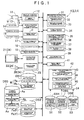
- FIG. 1 is a block diagram illustrating an outline of a constitution of a navigation apparatus 1 of the present embodiment.
- This navigation apparatus 1 includes a feature information collection apparatus 2, an image recognition apparatus 3, and a vehicle position recognition apparatus 4 as embodiments of the present invention.
- the navigation apparatus 1 setting a feature of a predetermined feature type as a target feature, learns the position of the target feature, using a result of image recognition of the target feature by an image recognition section 18. Then, by reflecting the result of learning of such a target feature in a feature database DB2, the navigation apparatus 1 enables correction of vehicle position information P using feature information F, even on a road that has not been effectively provided with the feature information F.
- the navigation apparatus 1 when the navigation apparatus 1 fails in image recognition of the target feature based on the feature information F, which is stored in the feature database DB2, the navigation apparatus 1 learns the failure, and by reflecting it in the feature database DB2, corrects the feature information F. Then, the navigation apparatus 1 performs navigation processing such as route guidance, based on the corrected vehicle position information P.
- Functional sections of the navigation apparatus 1 shown in FIG. 1 include specifically: an image information acquiring section 12, a vehicle position information acquiring section 16, a feature information acquiring section 17, an image recognition section 18, a vehicle position information correction section 19, a calculation section for navigation 20, a recognition information processing section 31, an estimated position judgment section 34, a feature information management section 35, a road information management section 39, a road attribute information acquiring section 41, and a target type determination section 42.
- These are constituted so that the functional sections to apply various kinds of processing to input data are implemented by hardware or software (programs), or both, with an arithmetic processing unit such as a central processing unit (CPU) serving as a core component.
- these functional sections are constituted so as to be able to transfer information to each other.
- each of databases DB1 to DB6 in the navigation apparatus 1 is provided with a recording medium that can store information and its drive unit, such as a hard disk drive, a DVD drive loaded with a DVD-ROM, or a CD drive loaded with a CD-ROM, as a hardware configuration.
- a recording medium that can store information and its drive unit, such as a hard disk drive, a DVD drive loaded with a DVD-ROM, or a CD drive loaded with a CD-ROM, as a hardware configuration.
- a map database DB1 is a database in which map information M divided into predetermined sections is stored.
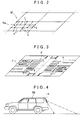
- FIG. 2 is a diagram illustrating an example of a constitution of the map information M stored in the map database DB 1.
- the map information M has road information Ra that indicates a road network, using connection relations between numerous nodes n, corresponding to intersections, and links k, corresponding to roads connecting between intersections.
- Each node n has information about a position (coordinate) on the map represented by latitude and longitude.
- the links k are connected via the nodes n.
- each link k as its attribute information, has information such as road type, area type, link length, road width, and interpolation points to render the link shape.
- the road type information is information about the road type classified by dividing roads into multiple types such as, for example, motorway, urban road, narrow road, and mountain road.
- the area type information is information about the area type classified by dividing areas provided with roads corresponding to the links k into multiple types such as, for example, Kanto and Kansai regions, and administrative areas, for example, prefectures, cities, wards, towns, and villages.
- the attribute information about these links k corresponds to road attribute information Rb (refer to FIG. 1 ).
- the map database DB 1 corresponds to a road information storage portion and a map information storage portion in the present invention. Note that, in FIG. 2 , only the road information Ra in one section is shown, the road information Ra in other sections being omitted.
- the feature database DB2 is a database in which information about various features provided on the road or in the neighborhood of the road, that is, the feature information F is stored.
- the feature information F is stored in two kinds of information, that is, initial feature information Fa and learned feature information Fb.
- the initial feature information Fa is the feature information F about multiple features that have been provided and stored in the feature database DB2 in advance.
- Such initial feature information Fa is provided only about certain areas such as metropolitan areas and trunk roads, among all areas for which the map information M including the road information Ra is provided.
- the learned feature information Fb is the feature information F stored in the feature database DB2 as a result of learning using a result of image recognition of a target feature by the image recognition section 18.
- feature information F collectively means the initial feature information Fa and the learned feature information Fb.
- the feature database DB2 corresponds to a feature information storage portion in the present invention.
- the features, whose feature information F is stored in the feature database DB2 include road markings (painted markings) provided on the road surface.
- FIG. 3 is a diagram illustrating an example of the feature information F of road markings stored in the feature database DB2.
- Such features as related to road markings include, for example, pedestrian crossings, stop lines, speed markings indicating maximum speed, etc., zebra zones, carriageway lines to divide the road into lanes along the road (including various kinds of solid, dashed, and double division lines), and carriageway markings to designate traveling direction of each lane (including arrow markings such as straight arrows and right turn arrows).
- the features, whose feature information F is stored can also include various features such as traffic lights, signs, overpasses, and tunnels.
- the feature information F also has as its contents position information of each feature and feature attribute information associated with it.
- the position information has information about a position (coordinate) on the map of each feature's representative point associated with the link k or node n constituting the road information Ra, and also has information about direction of each feature.
- the representative point is set in the neighborhood of the lateral and longitudinal center of each feature.
- the feature attribute information includes feature type information, as well as feature pattern information such as shape, size, and color of features.
- the feature type is specifically the information that indicates the type of features having basically the same pattern such as "pedestrian crossing,” “stop line,” and “speed marking (30 km/h).”
- the feature information F also has association information indicating relation with other nearby feature, and distance information between features indicating the distance to the other feature.
- the association information is information to enable prediction of another feature existing ahead, by recognizing a feature using image recognition while a vehicle 50 (refer to FIG. 5 , etc.) is traveling along the road.
- the distance information between features is information to accurately predict the distance from the vehicle 50 to such a feature as existing ahead.
- a learning database DB3 is a database that stores in it recognized position information Aa, which has been derived by a recognized position deriving section 32, and recognition failure information Ac, which has been derived by a recognition failure processing section 33, in such a state that the target feature corresponding to each piece of recognized position information Aa and recognition failure information Ac can be identified.
- recognition failure information Ac which has been derived by a recognition failure processing section 33
- a learning database DB3 corresponds to a recognition result storage portion in the present invention.
- the image information acquiring section 12 functions as an image information acquiring portion for acquiring image information G in the neighborhood of the vehicle taken by an imaging apparatus 11.
- the imaging apparatus 11 is a vehicle on-board camera or the like provided with an image pickup device and installed in a position from which the apparatus can take image of at least the road surface in the neighborhood of the vehicle 50.
- the imaging apparatus 11 it is preferable to use, for example, a back camera that takes image of the road surface rearward of the vehicle 50, as shown in FIG. 4 .
- the image information acquiring section 12 acquires image information taken by the imaging apparatus 11, at predetermined intervals of time through frame memory (not shown) or the like.
- the time interval, in this case, of acquiring the image information G can be set to, for example, 10 ms to 50 ms. In this way, the image information acquiring section 12 can continuously acquire the image information G of multiple frames taken by the imaging apparatus 11.
- the image information G acquired here is sent out to the image recognition section 18.
- the vehicle position information acquiring section 16 functions as a vehicle position information acquiring portion for acquiring vehicle position information P indicating the current position of the vehicle 50.
- the vehicle position information acquiring section 16 is connected to a global positioning system (GPS) receiver 13, a direction sensor 14, and a distance sensor 15.
- GPS global positioning system
- the GPS receiver 13 is a device to receive GPS signals from a GPS satellite.
- the GPS signals are received normally at intervals of one second, and sent out to the vehicle position information acquiring section 16.
- the vehicle position information acquiring section 16 can acquire information about the vehicle 50, such as a current position (latitude and longitude), orientation of travel, and traveling speed, by analyzing the signals from the GPS satellite received by the GPS receiver 13.
- the direction sensor 14 is a sensor to detect an orientation or a change in orientation of travel of the vehicle 50.
- the direction sensor 14 includes, for example, a gyro sensor, a geomagnetic sensor, an optical rotation sensor or rotary type resistance volume installed on the rotating part of steering, and an angular sensor installed on a wheel.
- the direction sensor 14 sends its detection result to the vehicle position information acquiring section 16.
- the distance sensor 15 is a sensor to detect a vehicle speed and movement distance of the vehicle 50.
- the distance sensor 15 includes, for example, a vehicle speed pulse sensor that sends out a pulse signal at every rotation of a given angle of a vehicle drive shaft or wheel, a yaw rate and G sensor to detect an acceleration of the vehicle 50, and a circuit to integrate the detected acceleration.
- the distance sensor 15 sends its detection result, that is, the information about vehicle speed and movement distance, to the vehicle position information acquiring section 16.
- the vehicle position information acquiring section 16 performs calculation to identify the vehicle position, using a known method.
- the vehicle position information acquiring section 16 also acquires the road information Ra about the neighborhood of the vehicle position extracted from the map database DB1, and by performing a known map matching based on the information, corrects the vehicle position so as to be situated on the road indicated by the road information Ra. In this way, the vehicle position information acquiring section 16 acquires the vehicle position information P including the information about the current position of the vehicle 50 represented by latitude and longitude, and the information about the orientation of travel of the vehicle 50.
- the feature information acquiring section 17 extracts and acquires the feature information F about the features existing in the neighborhood of the vehicle 50 from the feature database DB2, based on the vehicle position information P and others acquired in the vehicle position information acquiring section 16. As an example in the present embodiment, based on the vehicle position information P, the feature information acquiring section 17 extracts, from the feature database DB2, the feature information F about the target features existing between the current position of the vehicle 50 indicated by the vehicle position information P and the end of the link k representing the road on which the vehicle 50 is traveling. Then, the feature information F acquired by the feature information acquiring section 17 is sent out to the image recognition section 18 and the vehicle position information correction section 19.
- the feature information F about the target features which is extracted from the feature database DB2 by the feature information acquiring section 17, both the initial feature information Fa and the learned feature information Fb are included.
- the features to be rendered as target features are features that are to be recognized by an image recognition section 5.
- the target features are features of the feature types selected from various kinds of road markings, such as pedestrian crossings, stop lines, and speed markings, provided on the road surface.
- the image recognition section 18 functions as an image recognition portion for performing image recognition processing of the target feature included in the image information G acquired in the image information acquiring section 12.
- the image recognition section 18 performs two kinds of image recognition processing: one is image recognition processing for position correction to be used for correcting the vehicle position information P, and the other is image recognition processing for information collection to be used for learning the image recognition result of the target feature and reflecting the result in the feature database DB2.
- the image recognition section 18 refers to the feature information F, which has been acquired from the feature database DB2 by the feature information acquiring section 17 based on the vehicle position information P.
- the image recognition section 18 performs the image recognition processing for position correction if the target feature stored as the feature information F is judged to exist in the neighborhood of the vehicle 50, or performs the image recognition processing for information collection if the target feature stored as the feature information F is judged not to exist in the neighborhood of the vehicle 50.
- the purpose as also described later, is as follows: When the vehicle 50 is traveling on a road already provided with the feature information F, the image recognition section 18 corrects the vehicle position information P based on the result of image recognition by the image recognition processing for position correction and on the feature information F, or it modifies the feature information F if it has failed in the image recognition processing for position correction.
- the image recognition section 18 learns the position in which the target feature exists using the result of the image recognition processing for information collection.
- the judgment of whether or not the target feature stored as the feature information F exists in the neighborhood of the vehicle 50 is performed by checking whether or not the target feature stored as the feature information F exists between the current position of the vehicle 50 (vehicle position) indicated by the vehicle position information P and the end of the link k representing the road on which the vehicle 50 is traveling.
- the image recognition section 18 performs image recognition processing of the target feature indicated by the feature information F included in the image information G.
- the image recognition section 18 sets a predefined recognition area E (refer to FIG. 6 ) in which the target feature indicated by the feature information F is requested to be recognized, and performs image recognition of the target feature with respect to the image information G in the recognition area E.
- the recognition area E is set as a position range, on the link k indicated by the road information Ra, in which the target feature is presumed to exist.
- the image-taking area of actual road included in each piece of image information G can be obtained based on the vehicle position information P, using the positional relation between the vehicle position and the image-taking area that has been calculated in advance based on the installation position and installation angle, and viewing angle, etc. of the imaging apparatus 11 on the vehicle 50.
- the image recognition section 18 extracts the image information G corresponding to the recognition area E that is set for each target feature, and performs image recognition processing. Then, the result of image recognition of the target feature by the image recognition processing for position correction is used for correction of the vehicle position information P by the vehicle position information correction section 19.
- the image recognition section 18 performs also image recognition of the target feature outside the recognition area E set for each target feature. Such a result of image recognition of the target feature recognized outside the recognition area E is not used for correction of the vehicle position information P, but used for modification of the feature information F, as described later.
- the image recognition section 18 performs image recognition processing of the target feature included in the image information G.
- This image recognition processing cannot estimate the position in which the target feature exists because the processing is performed without using the feature information F stored in the feature database DB2. Therefore, in this image recognition processing for information collection, in response to determination of target types for each predefined road zone Z (refer to FIGs. 9 and 10 ) by the target type determination section 42, the image recognition section 18 performs image recognition processing of the target features of the target types determined for the road zone Z, with respect to each road zone Z.
- the road zone Z is a zone that is set on the node n and the link k indicated by the road information Ra.
- the road zone Z is set, for example, as end of link Za or middle of link Zb shown in FIG. 9 , or as on node Zc or on link Zd shown in FIG. 10 .
- the image-taking area of actual road included in each piece of image information G can be obtained based on the vehicle position information P, using the positional relation between the vehicle position and the image-taking area that has been calculated in advance based on the installation position and installation angle, and viewing angle, etc. of the imaging apparatus 11 on the vehicle 50.
- the image recognition section 18 extracts the image information G corresponding to each road zone Z, and performs image recognition processing of the target features of the target types determined for the road zone Z. Then, the result of image recognition of the target feature by the image recognition processing for information collection is rendered to be the recognized position information by the recognized position deriving section 32 as described later, and stored in the learning database DB3.
- the image recognition section 18 When performing image recognition of the target feature, the image recognition section 18 applies binary processing or edge detection processing to the image information G, and extracts contour information of the feature (road marking) included in the image information G. After that, by applying pattern matching between the extracted contour information of the feature and the feature quantity of the pattern of the target feature, the image recognition section 18 extracts the image of the target feature included in the image information G. Then, when performing the image recognition processing for position correction, the image recognition section 18 judges that it has succeeded in image recognition of the target feature if it has been able to extract the image of the target feature from the image information G inside the area set as the recognition area E.
- the image recognition section 18 judges that it has succeeded in image recognition of the target feature if it has been able to extract the image of the target feature from the image information G in each road zone Z. On the other hand, as a result of image recognition processing of all pieces of the image information G in the recognition area E or in each road zone Z, if the image recognition section 18 has not been able to extract the image of the target feature, it judges that the image recognition of the target feature has failed.
- the vehicle position information correction section 19 functions as a vehicle position information correction portion, which corrects the vehicle position information P, based on the result of image recognition processing of the target feature by the image recognition section 18 and on the position information of the target feature included in the feature information F about the target feature.
- the vehicle position information correction section 19 corrects the vehicle position information P along the traveling direction of the vehicle 50, using the result of image recognition of the target feature by the image recognition processing for position correction based on the feature information F in the image recognition section 18, and also using the position information of the target feature included in the feature information F.
- the vehicle position information correction section 19 first calculates the positional relation between the vehicle 50 and the target feature at the time of acquisition of the image information G including the image of the target feature. Next, based on the above calculation result of the positional relation between the vehicle 50 and the target feature and on the position information of the target feature included in the feature information F about the target feature, the vehicle position information correction section 19 calculates and acquires the high-accuracy position information about the vehicle 50 on the basis of the position information of the target feature (feature information F) in the traveling direction of the vehicle 50.
- the vehicle position information correction section 19 corrects the information about the current position in the traveling direction of the vehicle 50 included in the vehicle position information P, which has been acquired in the vehicle position information acquiring section 16.
- the vehicle position information acquiring section 16 acquires the high-accuracy vehicle position information P after the above correction.
- the calculation section for navigation 20 is a calculation processing portion, which operates according to an application program 23 to perform navigation functions such as vehicle position display, route search from a starting point to a destination, course guidance to a destination, and destination search.
- the calculation section for navigation 20 acquires, based on the vehicle position information P, the map information M about the neighborhood of the vehicle 50 from the map database DB1, and displays the image of the map on a display and input device 21, while superposing, based on the vehicle position information P, a vehicle position mark on the image of the map.
- the calculation section for navigation 20 performs route search from a predefined starting point to a destination.
- the calculation section for navigation 20 performs course guidance for the driver, using the display and input device 21, or a speech output device 22, or both.
- the calculation section for navigation 20 is connected to the display and input device 21, and the speech output device 22.
- the display and input device 21 is a combination of a display device such as a liquid crystal display device, and an input device such as a touch screen.
- the speech output device 22 includes a speaker, etc.
- the calculation section for navigation 20, the display and input device 21, and the speech output device 22 function as a guidance information output portion 24 in the present invention.
- the recognition information processing section 31 is a recognition information processing portion to perform processing in order to store into the learning database DB3 the information indicating the result of image recognition processing by the image recognition section 18, that is, specifically the recognized position information derived by the recognized position deriving section 32 and the recognition failure information generated by the recognition failure processing section 33. Therefore, in the present embodiment, the recognition information processing section 31 is provided with the recognized position deriving section 32 and the recognition failure processing section 33. Consequently, the details of processing performed by the recognized position deriving section 32 and the recognition failure processing section 33 will be described below, using FIGs. 5 to 8 .
- the recognized position deriving section 32 functions as a recognized position deriving portion to derive the recognized position of the target feature based on the vehicle position information P, in the case that the image recognition processing by the image recognition section 18 has succeeded in image recognition of the target feature.
- the recognized position deriving section 32 also generates the recognized position information Aa indicating the recognized position that has been derived, and stores the information into the learning database DB3 in such a state that the target feature successfully recognized by the image recognition can be identified.
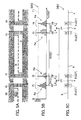
- FIG. 5 is an explanatory diagram for explaining an outline of collection processing of the feature information F using the result of the image recognition processing for information collection, in the case, for example, that the vehicle 50 travels on the road (link k) in which the feature information F is not provided.
- FIG. 5A shows an example of road markings (features) provided on an actual road on which the vehicle 50 travels.
- FIG. 5B shows an example of the recognized position information Aa stored in the learning database DB3.
- FIG. 5C shows an example of the feature database DB2 in which the learning result stored in the learning database DB3 is reflected.
- FIG. 5 shows an example in which the feature types are the same "pedestrian crossing" in all illustrated areas, unlike FIGs. 9 and 10 in which the feature types differ among the predefined road zones Z (Za to Zd).
- the recognized position deriving section 32 generates the recognized position information Aa for each target feature as a learning value with respect to the predefined position range to which the recognized position of the target feature recognized by the image recognition section 18 belongs. Then, the recognized position deriving section 32 increments the learning value for each of the position range every time when the target feature is recognized, and stores the result. The contents of processing by the recognized position deriving section 32 will be described in sequence below, using FIGs. 5A and 5B .
- the recognized position deriving section 32 first monitors whether or not the image recognition of the target feature is successful.
- the image recognition processing for information collection is applied to the target features that include all features whose feature type is "pedestrian crossing.” Therefore, in the example shown in FIG. 5A , the vehicle 50 should recognize, as target features, the images of the pedestrian crossings f1 to f4 at four locations along the traveling direction.
- the recognized position deriving section 32 derives the recognized position of the target feature, based on the image recognition result.
- the recognized position deriving section 32 derives the recognized position of the target feature as information indicating the position on the road of the target feature on the basis of the vehicle position information P. Consequently, the recognized position deriving section 32 calculates the positional relation between the vehicle 50 and the target feature at the time of acquisition of the image information G including the image of the target feature, base on the result of image recognition of the target feature by the image recognition section 18, and on the installation position, installation angle, and viewing angle of the imaging apparatus 11.
- the vehicle position information correction section 19 calculates the position of the target feature on the basis of the vehicle position information P.
- the recognized position deriving section 32 obtains the position of the target feature as a position of the representative point along the link k representing the road on which the vehicle 50 is traveling. Then the recognized position deriving section 32 derives the thus calculated position of the target feature, as a recognized position of the target feature. Because this recognized position of the target feature is derived on the basis of the vehicle position information P at the time of acquisition of the image information G including the image of the target feature, the recognized position is information about the position in which the error in the vehicle position information P is reflected.
- the recognized position deriving section 32 renders the recognized position of the target feature as a learning value with respect to the predefined position range, and the learning value with respect to the position range as the recognized position information Aa.
- the predefined position range is a range that is set by dividing the link k representing a road at constant intervals of distance, that is, for example, a range made by dividing the link k at intervals of 0.5 [m].
- the learning value is a value that is incremented with respect to the position range to which the recognized position of the target feature in the learning database DB3 belongs, every time when image recognition of one target feature is made successfully. For example, the learning value is incremented by one, every time when image recognition of one target feature is made successfully.
- the recognized position information Aa includes the information indicating the position range including the recognized position of the target feature, and the information of the learning value "1".
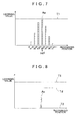
- FIG. 7 is an enlarged diagram of the part about the pedestrian crossing f1 of FIG. 5B showing the learning values stored in the learning database DB3.
- FIG. 5A if an image of the pedestrian crossing f1 as a target feature is successfully recognized, and also if the recognized position of the pedestrian crossing f1 derived by the recognized position deriving section 32 is located in the position range indicated as "a4" in FIG. 7 , a value of 1 is added to the learning value for the position range a4, as the dashed lines show in FIG. 7 .
- the learning database DB3 when the image of the same target feature (for example, the pedestrian crossing f1) is recognized multiple times because the vehicle 50 passes through the same road multiple times, in the learning database DB3, the learning values as the multiple pieces of the recognized position information Aa, which is generated every time when the target feature is recognized, are summed and accumulated for each position range indicating the recognized position of the target feature, as shown in FIG 5B and FIG. 7 . Then, as described later, when a learning value reaches a predefined learning threshold value T1 or more, the learned feature information Fb about the target feature is generated by a feature information generating section 36, and stored into the feature database DB2. In the example of FIG 5 , as shown in FIG 5C , learned feature information items Fb1 to Fb4 corresponding to the pedestrian crossings f1 to f4 are stored in the feature database DB2.
- the recognized position deriving section 32 performs the same processing as the processing that uses, to collect the feature information F, the result of the above-described image recognition processing for information collection.
- the recognized position deriving section 32 derives the recognized position of the target feature on the basis of the vehicle position information P, based on the result of image recognition of the target feature by the image recognition processing for position correction.
- the recognized position deriving section 32 generates the recognized position information Aa indicating the recognized position that has been derived, and stores the information into the learning database DB3 in such a state that the target feature successfully recognized by the image recognition can be identified.
- the feature information F stored in the feature database DB2 can be modified, using the result of image recognition of the target feature in the image recognition processing for position correction.
- the recognized position deriving section 32 stores the generated recognized position information Aa in association with the feature attribute information Ab, which indicates various attributes of the target feature.
- the attributes included in the feature attribute information Ab may only be those with which the one target feature can be distinguished from other target features. Therefore, for example, the feature attribute information Ab is provided with one or two or more items of information that are selected from the feature type of the target feature, the specific shape and size of the target feature, the link ID of the link k on which the target feature exists, and the approximate position of the target feature, etc.
- the above information items constituting the feature attribute information Ab about the target feature are generated based on information such as the result of image recognition of the target feature by the image recognition section 18 and the vehicle position information P at the time of acquisition of the image information G related to the image recognition processing.
- the recognition failure processing section 33 When, in its image recognition processing for position correction, the image recognition section 18 has failed in image recognition of the target feature indicated by the feature information F, the recognition failure processing section 33 generates the recognition failure information Ac, which indicates that the image recognition of the target feature indicated by the feature information F has failed, and stores the information into the learning database DB3 in such a state that the target feature that has failed to be recognized by the image recognition can be identified.
- the recognition failure processing section 33 functions as a recognition failure processing portion to perform recognition failure processing such as generating the recognition failure information Ac and storing it into the learning database DB3, as described above.
- FIG. 6 is an explanatory diagram for explaining an outline of modification processing of the feature information F using the result of image recognition processing for position correction, in the case, for example, that the vehicle 50 travels on the road (link k) in which the feature information F is already provided.
- FIG. 6A shows an example of road markings (features) provided on an actual road on which the vehicle 50 travels.
- FIG. 6B is an example showing the recognized position information Aa and the recognition failure information Ac, which are stored in the learning database DB3.
- FIG. 6C shows an example of the feature database DB2 in which the learning result stored in the learning database DB3 is reflected.
- FIG. 6 shows an example in which the image recognition processing for position correction is applied to the four "pedestrian crossings" as target features indicated by initial feature information items Fa11 to Fa14 shown in FIG. 6C .
- the recognition failure processing section 33 generates the recognition failure information Ac for each target feature as a learning value with respect to the target feature. Then, the recognition failure processing section 33 decrements the learning value with respect to the target feature every time when the image of the target feature fails to be recognized, and stores the result. The contents of processing by the recognition failure processing section 33 will be described in sequence below, using FIGs. 6A to 6C .
- the recognition failure processing section 33 first monitors whether or not the image recognition of the target feature is successful in the predefined recognition area E, which has been set with respect to the target feature.
- the vehicle 50 travels on the road (link k) provided with the initial feature information Fa
- image recognition is requested in the image recognition section 18 to recognize sequentially the four "pedestrian crossings" indicated by the initial feature information items Fa11 to Fa14, as target features.
- the pedestrian crossing f12 indicated by the initial feature information item Fa12 is blurring and fading
- the pedestrian crossing indicated by the initial feature information item Fa13 has completely disappeared, in the present example.
- the recognition failure processing section 33 monitors also whether or not the image of the target feature is recognized outside the recognition area E, which has been set with respect to each target feature.
- a pedestrian crossing f5 that is not provided as the initial feature information Fa is placed outside the recognition area E13, which has been set with respect to the target feature (pedestrian crossing) indicated by the initial feature information item Fa13, and the image of this pedestrian crossing f5 is recognized.
- an initial value Td of the learning value with respect to the target feature indicated by each item of the initial feature information Fa is set corresponding to each item of the initial feature information Fa, which has been prepared and stored in the feature database DB2 in advance, and the initial value Td is stored in the learning database DB3.
- the initial value Td of the learning value is set to a lower value than the learning threshold value T1. Then, when the image of the target feature indicated by the initial feature information Fa fails to be recognized, the recognition failure processing section 33 generates the recognition failure information Ac for the target feature as a learning value with respect to the target feature.
- the recognition failure processing section 33 decrements the learning value with respect to the target feature, which is stored in the learning database DB3, in a sequence starting from the initial value Td, and stores the result.
- the learning value is decremented by one, every time when image recognition of the target feature fails.
- the recognition failure information Ac includes the information with which the target feature indicated by the initial feature information Fa or the initial feature information Fa itself can be identified, and the information of the learning value "1".
- both the initial value Td of the learning value stored in the learning database DB3 and the recognition failure information Ac generated by the recognition failure processing section 33 are stored in association with the feature attribute information Ab, which indicates various attributes of the target feature.
- the feature attribute information Ab mentioned above is the same information as the information that is stored in association with the recognized position information Aa.
- FIG 8 is an enlarged diagram of the part about the pedestrian crossing f12 (initial feature information item Fa12) of FIG. 6B showing the learning values stored in the learning database DB3.
- FIG. 6A if the image of the pedestrian crossing f12 as a target feature indicated by the initial feature information item Fa12 fails to be recognized, a value of 1 is subtracted from the learning value for the target feature, as the dashed lines show in FIG 8 . Further, if the image of the same target feature fails to be recognized multiple times when the vehicle 50 passes through the same road multiple times, the learning value decreases until it eventually becomes zero, like, for example, the learning value for the pedestrian crossing f13 indicated by the initial feature information item Fa13 in FIG. 6B .
- the initial feature information Fa indicating the target feature is deleted from the feature database DB2 by a deletion management section 38, because a deletion threshold value T2 is set to zero.
- the initial feature information item Fa13 is deleted from the feature database DB2 because the learning value for the pedestrian crossing f13 indicated by the initial feature information item Fa13 has become zero.
- the recognition failure processing section 33 even if the recognition failure processing section 33 fails in image recognition of the target feature indicated by the learned feature information Fb when performing the image recognition processing for position correction, it does not store the recognition failure information Ac about the target feature into the learning database DB3.
- the recognition failure processing section 33 when the image of the target feature indicated by the learned feature information Fb fails to be recognized, the recognition failure processing section 33 generates the recognition failure information Ac for the target feature as a learning value with respect to the target feature. Then, every time when the image of the target feature fails to be recognized, the recognition failure processing section 33 decrements the learning value with respect to the target feature, which is stored in the learning database DB3, in a sequence starting from the initial value Td, and stores the result.
- the learned feature information Fb can be treated in the same way as the initial feature information Fa.
- the recognition failure processing section 33 does not store the learning value as the recognition failure information Ac.
- the learning values for the pedestrian crossings f11 and f14 stored in the learning database DB3 are maintained intact at the initial value Td, as shown in Fig 6B .
- the recognition failure processing section 33 judges whether or not the image of the target feature is recognized outside the recognition area E that has been set for each target feature. If the image of the target feature is recognized outside the recognition area E that has been set for each target feature, the recognized position deriving section 32 performs the same processing as the processing that uses, to collect the feature information F, the result of the image recognition processing for information collection, as described above. In other words, the recognized position deriving section 32 derives the recognized position of the target feature on the basis of the vehicle position information P, based on the result of image recognition of the target feature by the image recognition processing for position correction. Then, the recognized position deriving section 32 generates the recognized position information Aa indicating the recognized position that has been derived, and stores the information into the learning database DB3 in such a state that the target feature successfully recognized by the image recognition can be identified.
- the pedestrian crossing f5 for which the initial feature information Fa is not provided is placed at the nearer side along the traveling direction of the vehicle 50 than the recognition area E13 that has been set for the target feature (pedestrian crossing) indicated by the initial feature information item Fa13. Therefore, in the present example, this pedestrian crossing f5 is the target feature whose image is recognized outside the recognition area E that has been set for each target feature.
- the recognized position deriving section 32 instead of the recognition failure processing section 33, performs the same processing as the processing that uses, to collect the feature information F, the result of the image recognition processing for information collection.
- the recognized position deriving section 32 increments the learning value as the recognized position information Aa about the pedestrian crossing f5, with respect to the position range to which the recognized position of the pedestrian crossing f5 in the learning database DB3 belongs. Further, when the image of the pedestrian crossing f5 is recognized multiple times because the vehicle 50 passes through the same road multiple times, the learning values as the multiple pieces of the recognized position information Aa, which is generated every time when the pedestrian crossing f5 is recognized, are summed and accumulated in the learning database DB3, as shown in FIG. 6B .
- the feature information generating section 36 When the learning value for this pedestrian crossing f5 reaches the predefined learning threshold value T1 or more, an estimated position pg is judged by the estimated position judgment section 34. Then, as shown in FIG. 6C , the feature information generating section 36 generates the learned feature information item Fb5, and stores it into the feature database DB2.
- the feature information F stored in the feature database DB2 can be modified appropriately in accordance with the current status, by deleting the initial feature information Fa from the feature database DB2 and by adding the learned feature information Fb to the feature database DB2, as described above.
- the recognition failure processing section 33 also stores the generated recognition failure information Ac in association with the feature attribute information Ab, which indicates various attributes of the target feature.
- the feature attribute information Ab mentioned above is the same information as the information that is stored in association with the recognized position information Aa.
- the estimated position judgment section 34 functions as an estimated position judgment portion to judge the estimated position pg of the target feature (refer to FIG. 5 ), based on the multiple pieces of the recognized position information Aa about the same target feature, which have been stored in the learning database DB3 as a result of multiple times of image recognition of the same target feature.
- the estimated position judgment section 34 judges the representative value of the distribution to be the estimated position pg of the target feature.
- a mode value is used as a representative value of the distribution.
- the estimated position judgment section 34 judges the position representing the position range that has a mode value to be the estimated position pg of the target feature, based on the distribution of the learning values as the recognized position information Aa about the target feature stored in the learning database DB3.
- a judgment method is described in the case of judging the estimated position pg of the pedestrian crossing f1 in the example shown in FIG. 5 . As shown in FIG.
- the estimated position judgment section 34 judges the position representing the position range a4, for example, the center position pg4 of the position range a4, to be the estimated position pg of the pedestrian crossing f1.
- the feature information management section 35 functions as a feature information management portion to manage the feature information F stored in the feature database DB2, based on the result of learning of the target feature stored in the learning database DB3.
- the feature information management section 35 includes the feature information generating section 36, a distance judgment section between features 37, and the deletion management section 38. These sections will be described individually below.
- the feature information generating section 36 functions as a feature information generating portion to generate the learned feature information Fb, based on the result of learning of the target feature stored in the learning database DB3.
- the feature information generating section 36 generates the learned feature information Fb that associates the position information indicating the estimated position pg of each target feature judged by the estimated position judgment section 34 with the feature attribute information based on the image recognition result of the target feature recognized by the image recognition section 18.
- the feature attribute information constituting the learned feature information Fb is generated using the content of the feature attribute information Ab, which is stored in the learning database DB3 in association with the recognized position information Aa about the target feature.
- the learned feature information Fb is generated as information provided with the position information and the feature attribute information associated with it. Then, the learned feature information Fb generated in the feature information generating section 36 is stored into the feature database DB2.
- the learned feature information items Fb1 to Fb4 shown in FIG. 5C , and the learned feature information item Fb5 shown in FIG. 6C are generated by the feature information generating section 36, and stored in the feature database DB2.
- the black square " ⁇ " shown in these diagrams represents the estimated position pg of each target feature indicated by the position information of each of the learned feature information items Fb 1 to Fb5.
- the distance judgment section between features 37 functions as a distance judgment portion between features to judge a distance between features D that indicates a distance between two target features, based on the multiple pieces of the recognized position information Aa about the two target features.
- the distance judgment section between features 37 using the information about the estimated positions pg of two target features judged by the estimated position judgment section 34, calculates the distance between the estimated position pg of one target feature and the estimated position pg of the other target feature to obtain the distance between features D of the two target features.
- the distance judgment section between features 37 obtains the distance between two neighboring target features.
- the distance judgment section between features 37 judges and obtains distance between features D1 between the pedestrian crossings f1 and f2, distance between features D2 between the pedestrian crossings f2 and f3, and distance between features D3 between the pedestrian crossings f3 and f4.
- the information about the distance between features D judged by the distance judgment section between features 37 is used as information that constitutes the learned feature information Fb, which is generated by the above-described feature information generating section 36.
- the learned feature information Fb about each target feature is generated as information that includes the associated information indicating the relation between the target feature and the other neighboring feature, and also includes the distance information between features indicating the distance between features D between the target feature and the other feature.
- the deletion management section 38 functions as a deletion management portion to delete the feature information F stored in the feature database DB2, based on the result of learning of the target feature stored in the learning database DB3. In other words, the deletion management section 38 deletes the feature information F about the target feature stored in the feature database DB2, based on the multiple pieces of the recognition failure information Ac about the same target feature, which have been stored in the learning database DB3 as a result of multiple times of image recognition of the same target feature. Specifically, when the learning value for each target feature becomes the predefined deletion threshold value T2 or less, the deletion management section 38 deletes the feature information F about the target feature. As described above, in the present embodiment, the deletion threshold value T2 is set to zero. Therefore, when the learning value as the recognition failure information Ac, which is stored in the learning database DB3, with respect to one target feature becomes zero, the deletion management section 38 deletes the feature information F about the target feature from the feature database DB2.
- the deletion management section 38 performs only the deletion processing related to the initial feature information Fa, from the feature database DB2.
- the deletion management section 38 deletes the initial feature information item Fa13 from the feature database DB2, when the learning value for the pedestrian crossing f13 indicated by the initial feature information item Fa13 becomes zero.
- the deletion management section 38 performs also the deletion processing related to the learned feature information Fb, from the feature database DB2.
- the road information management section 39 functions as a road information management portion to modify either or both of the road information Ra and the road attribute information Rb, which are stored in the map database DB1.
- the road information management section 39 modifies either or both of the position information of the node n and the length information of the link k connecting the two nodes n, both information items being included in the road information Ra.
- the road information management section 39 determines either or both of the position of the node n and the length of the link k, based on the position information indicating the estimated positions pg, which have been judged by the estimated position judgment section 34, of two target features placed on the opposite sides of and at approximately equal distance from the node n.
- the target features placed on the opposite sides of and at approximately equal distance from the node n correspond to, for example, pedestrian crossings.
- the road information management section 39 modifies the road information Ra in accordance with the obtained data. In this way, the road information Ra stored in the map database DB 1 can be modified appropriately in accordance with the current status, by using the result of learning of the target features.
- the road attribute information acquiring section 41 functions as a road attribute information acquiring portion to acquire from the map database DB 1 the road attribute information Rb about the road (link k) on which the vehicle 50 is traveling, based on the vehicle position information P.
- the road attribute information Rb stored in the map database DB1 includes information such as road type, area type, link length, road width, and interpolation points to render the link shape.
- the road attribute information acquiring section 41 selects from the above-mentioned items the information items required for determination of the target types by the target type determination section 42 described later, and acquires them as the road attribute information Rb, from the map database DB1.
- the road attribute information acquiring section 41 acquires the road type information and the area type information as the road attribute information Rb.
- the road type information is information about the road type classified by dividing roads into multiple types such as, for example, motorway, urban road, narrow road, and mountain road.
- the area type information is information about the area type classified by dividing areas provided with roads corresponding to the links k into multiple types such as, for example, Kanto and Kansai regions, and administrative areas, for example, prefectures, cities, wards, towns, and villages. Therefore, as the road attribute information Rb about the road (link k) on which the vehicle 50 is traveling, the road attribute information acquiring section 41 acquires information such as, for example, "road type: urban road, area type: Aichi Prefecture.”
- a recognition attribute database DB4 is a database in which is stored recognition ratio information S 1 as recognition attribute information about all feature types that can be target types, and functions as a recognition attribute information storage portion.
- the recognition ratio information S 1 is information indicating, in the case of the image recognition processing for information collection by the image recognition section 18, the predicted recognition ratio of a feature of each feature type, the predicted recognition ratio being determined based on the properties inherent in each feature type.
- the recognition ratio information S1 is information that indicates a theoretical ratio of success in recognizing the image of a target feature of each feature type.
- the properties inherent in each feature type that affect the recognition ratio of each feature type include, for example, the shape, size, color, or likelihood of blurring of each feature type.
- a feature type has a distinguishing shape that is unlikely to be mistaken for other feature type and easy to be recognized, its recognition ratio tends to be high.
- the size of a feature the larger in the direction of road width a feature is, the higher its possibility to be included in the image information G is, when taken by the imaging apparatus 11; thus, its recognition ratio tends to be high.
- the color of a feature the larger its contrast to the color of the road surface is, the higher its recognition ratio tends to be.
- the likelihood of blurring of a feature the higher the possibility of blurring is, the higher the possibility of failure in image recognition is; thus, its recognition ratio tends to be low.
- the recognition ratio information S1 of each feature type which is stored into the recognition attribute database DB4, becomes the information indicating the predicted values of recognition ratio, which are predefined based on the properties inherent in each of these feature types.
- An appearance frequency database DB5 is a database in which is stored appearance frequency information S2 about all feature types that can be target types, indicating the appearance frequency of each feature type depending on the road attribute indicated by the road attribute information Rb, and functions as an appearance frequency information storage portion.
- the appearance frequency information S2 is information indicating the appearance frequency of each feature type on each road (link k) of the multiple road attributes indicated by the road attribute information Rb.
- the road type information and the area type information are used as the road attribute information Rb. Therefore, the appearance frequency information S2 of each feature type about all combinations of the road type information and the area type information is defined in the appearance frequency database DB5.
- the appearance frequency of each feature type depending on the road attribute as described above is obtained statistically, based on the result of field research about feature types of features existing on the road of each road attribute.
- the appearance frequency information S2 in the present embodiment, is information represented by the number of appearing features of each feature type per unit length of road, and more specifically, it is information represented by the number of appearance per road length of 1 [km]. Therefore, when, for example, the appearance frequency information S2 has a value of "10.3" in the case that the road attribute is "road type: urban road, area type: Aichi Prefecture" and the feature type is "pedestrian crossing," the appearance frequency information S2 means that on the urban roads in Aichi Prefecture, statistically 10.3 pedestrian crossings are provided for each 1 [km] of road length.
- An arrangement tendency database DB6 is a database in which is stored zone information S3 about each feature type as arrangement tendency information indicating the arrangement tendency of all feature types that can be target types on the road, and functions as an arrangement tendency information storage portion.
- the zone information S3 is information indicating in which of multiple road zones Z divided in the longitudinal direction of the road (link k) with respect to an intersection (node n) a feature of each feature type is most likely to be placed.
- the zone information S3 is information indicating the road zone Z in which a feature of each feature type is likely to be placed.
- the zone information S3 divides the road into the road zones Z that differ depending on the road types indicated by the road attribute information Rb.
- the road (link k) is divided along its longitudinal direction into the two road zones Z, that is, "end of link Za” corresponding to an end area of road and “middle of link Zb" corresponding to a middle area of road, as shown in FIG. 9 .
- the road (link k) is divided along its longitudinal direction into the two road zones Z, that is, "on node Zc” corresponding to a middle area of intersection and “on link Zd” corresponding to a road area other than intersection, as shown in FIG. 10 .
- the road zone Z indicated by the zone information S3 whose feature type is "pedestrian crossing” is "end of link Za” for urban road, and "on link Zd” for narrow road.
- the target type determination section 42 functions as a target type determination portion to determine target types, based on the road attribute information Rb acquired by the road attribute information acquiring section 41, and on the recognition attribute information for each feature type predefined in relation to image recognition processing.
- the target types are one or two or more feature types that are targets of the image recognition processing for information collection by the image recognition section 18.
- the target type determination section 42 selects the types from the feature types related to various road markings, such as pedestrian crossings, stop lines, and speed markings, provided on the road, and determines the selected types as the target types.
- the target type determination section 42 includes a recognition frequency deriving section 43, a target type determination calculation section 44, and recognition success/failure management section 45. Therefore, the details of processing performed by the above-mentioned sections will be described below, using FIGs. 9 to 10 .
- FIG. 9 is a diagram illustrating a specific example of divisions of the road zone Z and the target type determination processing, in the case that the road type is an urban road.
- FIG. 10 is a diagram illustrating a specific example of divisions of the road zone Z and the target type determination processing, in the case that the road type is a narrow road.
- FIGs. 9A and 10A show specific examples of divisions of the road zone Z
- FIGs. 9B and 10B show specific examples of the target type determination processing.
- the recognition frequency deriving section 43 functions as a recognition frequency deriving portion to derive a recognition frequency of each feature type, based on the appearance frequency of each feature type depending on the road attribute indicated by the road attribute information Rb, which has been acquired by the road attribute information acquiring section 41, and also based on the degree of ease of recognition in image recognition processing of each feature type indicated by the recognition attribute information.
- the recognition frequency deriving section 43 first searches the appearance frequency database DB5, based on the road attribute information Rb acquired by the road attribute information acquiring section 41, and then acquires the appearance frequency information S2, which indicates the appearance frequency of each feature type depending on the road attribute indicated by the road attribute information Rb.
- the recognition frequency deriving section 43 acquires the appearance frequency information S2 corresponding to the combination of the road type information and the area type information, with respect to each feature type.
- the appearance frequency information S2 about multiple feature types corresponding to this combination of the road type information and the area type information is acquired from the appearance frequency database DB5, as shown in FIG. 9B .
- the information including "pedestrian crossing: 10.3,” “stop line: 8.7,” “arrow: 15.2,” “no u-turn: 3.3,” and "maximum speed: 3.1” is acquired as the appearance frequency information S2 about each of the feature types.
- the appearance frequency information S2 about multiple feature types corresponding to this combination of the road type information and the area type information is acquired from the appearance frequency database DB5, as shown in FIG. 10B .
- the information including "T-intersection: 9.8,” “cross intersection: 10.5,” “stop line: 19.6,” “pedestrian crossing: 5.1,” and “pedestrian crossing ahead: 5.3” is acquired as the appearance frequency information S2 about each of the feature types.
- these diagrams show the examples in each of which the appearance frequency information S2 about five feature types is acquired. However, the appearance frequency information S2 about more number of feature types is acquired actually.
- the recognition frequency deriving section 43 acquires the recognition ratio information S1 as recognition attribute information about each feature type, from the recognition attribute database DB4.
- the recognition frequency deriving section 43 searches the recognition attribute database DB4 and acquires the recognition ratio information S1.
- the recognition ratio information S 1 is acquired as the recognition ratio information S 1 about each of the feature types.
- the recognition ratio information S 1 is acquired as the recognition ratio information S 1 about each of the feature types.
- the information including "T-intersection: 90%,” “cross intersection: 80%,” “stop line: 55%,” “pedestrian crossing: 80%,” and “pedestrian crossing ahead: 60%” is acquired as the recognition ratio information S 1 about each of the feature types.
- the recognition frequency deriving section 43 derives the recognition frequency of each feature type, based on the appearance frequency information S2 and the recognition ratio information S 1 acquired.
- the recognition frequency deriving section 43 obtains, as a recognition frequency, the value by multiplying the appearance frequency of each feature type indicated by the appearance frequency information S2 and the predicted recognition ratio of a feature of each feature type indicated by the recognition ratio information S1, as represented by the following formula (1).
- Recognition frequency Appearance frequency ⁇ Predicted recognition ratio
- this recognition frequency is obtained as a value corresponding to a weighted appearance frequency produced by multiplying, as a weighting factor, the predicted recognition ratio in image recognition processing of a feature of each feature type, to the appearance frequency of the feature of each feature type depending on the road attribute of the road (link k) on which the vehicle 50 is traveling.
- the recognition frequency becomes the information indicating an overall recognition ratio of a feature of each feature type, in the case in which the vehicle 50 performs image recognition processing of features while traveling on the road (link k) having road attributes indicated by the road attribute information Rb.
- the recognition frequency with respect to the feature type "pedestrian crossing” is obtained to be “8.2” by multiplying "predicted recognition ratio: 80%" to "appearance frequency: 10.3.”
- the recognition frequency of each feature type is obtained to be "stop line: 4.8,” “arrow: 10.6,” “no u-turn: 3.0,” or "maximum speed: 2.5.”
- the recognition frequency of each feature type is obtained to be "T-intersection: 8.8,” “cross intersection: 8.4,” “stop line: 10.8,” “pedestrian crossing: 4.1,” or “pedestrian crossing ahead: 3.2.”
- the recognition frequency deriving section 43 derives the recognition frequency of each feature type as described above.
- the target type determination calculation section 44 determines the target types, which are one or two or more feature types as targets of the image recognition processing for information collection, based on the recognition frequency of each feature type derived by the recognition frequency deriving section 43. In the present embodiment, depending on the recognition frequency of each feature type derived by the recognition frequency deriving section 43, the target type determination calculation section 44 determines one or two or more feature types that are ranked the highest in the recognition frequencies to be the target types, among all feature types possible to be the target types.
- the target type determination calculation section 44 determines the target types, putting a high priority on the feature types for which the arrangement tendency indicated by the zone information S3 of each feature type coincides with the arrangement of the vehicle 50 on the road (link k) based on the vehicle position information P.
- the target type determination calculation section 44 determines the priority of each feature type in descending order from the highest rank in the recognition frequency, for each separate road zone Z indicated by each item of the zone information S3.
- the target type determination calculation section 44 determines the orders of priority of the feature types whose road zone Z is “end of link Za” as “pedestrian crossing: 1" and “stop line: 2,” in descending order from the highest rank in the recognition frequency among the feature types included in the road zone Z.
- the target type determination calculation section 44 determines the orders of priority of the feature types whose road zone Z is "middle of link Zb" as “arrow: 1," “no u-turn: 2,” and “maximum speed: 3,” in descending order from the highest rank in the recognition frequency among the feature types included in the road zone Z.
- "end of link Za” contains the zone in the neighborhood of the intersection (node n) including pedestrian crossings placed on both sides of the intersection (node n) and a stop line, and the other zone on the road (link k) is included in "middle of link Zb.”
- the priority orders of both "T-intersection” and “cross intersection” are “1" in spite of the difference in their recognition frequency. This is because “T-intersection” and “cross intersection” are not placed in the same position, causing no positional conflict. Furthermore, because they share a common shape, a common image recognition processing can be used to recognize their images by setting both of them as target types at the same time.
- the target type determination calculation section 44 determines the orders of priority of the feature types whose road zone Z is "on link Zd" as "stop line: 1," “pedestrian crossing: 2,” and “pedestrian crossing ahead: 3,” in descending order from the highest rank in the recognition frequency among the feature types included in the road zone Z. In the example shown in FIG.
- on link Zd contains the zone on the road (link k) including pedestrian crossings and stop lines placed on both sides of the intersection (node n), and the other zone in the neighborhood of the intersection (node n) is included in "on node Zc.”
- the target type determination calculation section 44 determines the target types for each road zone Z, based on the order of priority of each feature type for each road zone Z.
- the target type determination calculation section 44 determines the feature types whose order of priority for each road zone Z is "1" to be the target types. Therefore, in the example shown in FIG. 9 , the feature type is determined to be "pedestrian crossing" when the road zone Z is "end of link Za,” and the feature type is determined to be “arrow” when the road zone Z is "middle of link Zb.”
- the feature types are determined to be “T-intersection” and “cross intersection” when the road zone Z is "on node Zc,” and the feature type is determined to be “stop line” when the road zone Z is “on link Zd.”
- the target type determination calculation section 44 in determining the target types as described above, refers to the type failure information S4 stored in the recognition success/failure management section 45, and based on the past information about the success or failure of image recognition of the target feature, determines the target types. In this case, the target type determination calculation section 44 first searches the recognition success/failure management section 45, based on the vehicle position information P, and extracts the type failure information S4 about the road zone Z in which the vehicle 50 travels.
- the type failure information S4 is information indicating that image recognition of features of target types determined for each road zone Z has failed in the past, and the information includes information that indicates the target types whose image has failed to be recognized by the image recognition and information that indicates the particular road zone Z corresponding to the area in which the image recognition has failed.
- the target type determination calculation section 44 makes an adjustment to change orders of priority of the feature types with respect to the road zone Z, so that the order of the feature type indicated by the type failure information S4 moves down. Specifically, the target type determination calculation section 44 changes the orders of priority so that the order of the feature type indicated by the type failure information S4 comes to the lowest rank. At the same time, the target type determination calculation section 44 also moves up the orders of priority of other feature types in turn. Then, the target type determination calculation section 44 determines the feature types whose order of priority after the change is "1" to be the target types. For example, in the example shown in FIG.
- the target type determination calculation section 44 changes the order of priority of "arrow" to the lowest order. Consequently, as orders of priority in the particular road zone Z, "no u-turn” moves up to "1", and “maximum speed” to "2" in turn. As a result, in this case, the target type determination calculation section 44 determines "no u-turn" to be the target type, according to the order of priority after change.
- the recognition success/failure management section 45 functions as a recognition success/failure management portion to manage information about the success or failure of image recognition of target features in the past, in relation to the image recognition processing for information collection. For this purpose, based on the vehicle position information P, the recognition success/failure management section 45 generates the type failure information S4, for each road zone Z (an example of predefined area), as recognition success/failure information indicating the success or failure of image recognition of the target features of the target types determined by the target type determination calculation section 44, and then stores the generated type failure information S4.
- the type failure information S4 is information to indicate the fact that the image recognition has failed. Therefore, in this example, the type failure information S4 includes information that indicates the target types whose image has failed to be recognized by the image recognition and information that indicates the particular road zone Z corresponding to the area in which the image recognition has failed.
- the "particular road zone Z" included in the type failure information S4 is information with which a road zone Z in which the image recognition has failed can be identified, unlike the zone information S3 stored in the arrangement tendency database DB6, which identifies only the type of road zone Z such as "end of link Za” or "middle of link Zb.” Therefore, the "particular road zone Z" included in the type failure information S4 is obtained based on the vehicle position information P at the time of passing the particular road zone Z in which the image recognition has failed, and also based on the road information Ra. Then, the particular road zone Z is rendered, for example, to be information associated with a particular link k in which the particular road zone Z exists.
- the recognition success/failure management section 45 counts the number of failures in the image recognition, and if a predefined number (for example, 1,5, or 10) of failures have occurred consecutively, generates and stores the type failure information S4.
- a predefined number for example, 1,5, or 10
- the target types with respect to the particular road zone Z are changed. Therefore, in the image recognition processing for information collection, it becomes possible to efficiently perform image recognition of target features, and learning of the target features.
- FIG. 11 is a flowchart showing an order of overall operation processing, including the vehicle position information correction method, of the navigation apparatus 1 of the present embodiment.
- FIG. 12 is a flowchart showing details of a processing order of feature information collection processing as the feature information collection method of the present embodiment.
- FIG. 13 is a flowchart showing details of a processing order of target type determination processing as the target type determination method of the present embodiment.
- FIG. 14 is a flowchart showing details of a processing order of feature information modification processing as the feature information modification method of the present embodiment.
- the navigation apparatus 1 first the vehicle position information acquiring section 16 acquires the vehicle position information P (step #01). Next, the image information acquiring section 12 acquires the image information G in the neighborhood of the vehicle 50 taken by the imaging apparatus 11 (step #02). Then, the feature information acquiring section 17 acquires from the feature database DB2 the feature information F about target features existing between the current position of the vehicle 50 (vehicle position) indicated by the vehicle position information P and the end of the link k representing the road on which the vehicle 50 is traveling (step #03). If the feature information F has not been acquired in step #03 (step #04: No), the navigation apparatus 1 executes the feature information collection processing (step #07). The feature information collection processing will later be described in detail, based on a flowchart shown in FIG. 12 .
- step #05 the image recognition section 18 sets a recognition area E for each target feature indicated by each piece of the feature information F acquired in step #03, and performs image recognition processing, in the next step (step #05).
- This image recognition processing in step #05 is the image recognition processing for position correction by the image recognition section 18, described above.
- step #06: Yes the vehicle position information correction section 19 corrects the vehicle position information P, based on the result of image recognition of the target feature and on the position information about the target feature included in the feature information F about the target feature (step #08).
- step #09 the navigation apparatus 1 executes the feature information modification processing (step #09).
- the feature information modification processing will later be described in detail, based on a flowchart shown in FIG. 14 . Then, the overall operation processing of the navigation apparatus 1 ends as described above.
- the target type determination section 42 performs the target type determination processing (step #21).
- This target type determination processing is a processing to determine, as a target type among multiple feature types that can be a target type, the feature type to be recognized by the image recognition processing for information collection.
- the target type is determined for each predefined road zone Z (refer to FIGs. 9 and 10 ).
- the target type determination processing will later be described in detail, based on a flowchart shown in FIG. 13 .
- the image recognition section 18 performs image recognition processing of the target feature in each road zone Z, depending on the target type determined for each road zone Z in step #21 (step #22).
- the image recognition section 18 sets the feature of the target type determined for each road zone Z as a target feature, and performs image recognition of the target feature.
- This image recognition processing in step #22 is the image recognition processing for information collection by the image recognition section 18, described above. Then, if the image of the target feature has not been able to be recognized in one road zone Z (step #23: No), the type failure information S4 (refer to FIG. 1 ) indicating a failure in image recognition of the target type, which has been determined in step #21, in the road zone Z is stored into the recognition success/failure management section 45 (step #30).
- the recognized position deriving section 32 derives the recognized position of the target feature, based on the vehicle position information P acquired in step #01 (step #24).
- the recognized position deriving section 32 generates the recognized position information Aa indicating the recognized position of the target feature, derived in step #24, as a learning value for the predefined position range to which the recognized position belongs, and, by incrementing the learning value for each position range, as shown in FIGs. 5B and 7 , stores it into the learning database DB3 (step #25).
- the learning value as the recognized position information Aa about the target feature stored in the learning database DB3 is less than the predefined learning threshold value T1 (step #26: No), processing ends without further operation.
- the estimated position judgment section 34 judges the estimated position pg of the target feature (step #27). Then, the feature information generating section 36 generates the learned feature information Fb about the target feature that associates the estimated position pg judged in step #27 with the feature attribute information based on the image recognition result (step #28). Then, the learned feature information Fb, thus generated, is stored into the feature database DB2 (step #29).
- the feature information collection processing ends as described above.
- the road attribute information acquiring section 41 acquires, from the map database DB1, the road attribute information Rb (refer to FIG. 1 ) about the road (link k) on which the vehicle 50 is traveling, based on the vehicle position information P acquired in step #01 (step #41).
- the recognition frequency deriving section 43 in the target type determination section 42 acquires, from the appearance frequency database DB5, the appearance frequency information S2 (refer to FIG. 1 ) for each feature type that depends on the road attribute information Rb acquired in step #41 (step #42).
- the recognition frequency deriving section 43 acquires the recognition ratio information S 1 about each feature type, from the recognition attribute database DB4 (step #43). Then, based on the information acquired by steps #41 to #43, the recognition frequency deriving section 43 derives the recognition frequency of each feature type (step #44).
- the method for deriving the recognition frequency of each feature type by the recognition frequency deriving section 43 is as already described above.
- the target type determination calculation section 44 in the target type determination section 42 acquires, from the arrangement tendency database DB6, the zone information S3 as arrangement tendency information about each feature type (step #45). Then, the target type determination calculation section 44 determines the priority order of each feature type in each predefined road zone Z indicated by the zone information S3 (step #46). Specifically, as described above, the target type determination calculation section 44 determines the priority order of each feature type so that the feature type with higher recognition frequency is ranked higher in each predefined road zone Z indicated by the zone information S3.
- the target type determination section 42 refers to the recognition success/failure management section 45 (step #47), and judges whether or not the type failure information S4 about the road zone Z, for which the priority orders have been determined in step #46, is stored in the recognition success/failure management section 45 (step #48).
- step #48 No
- processing proceeds to #50.
- step #48 Yes
- the priority orders for the road zone Z having the type failure information S4 are changed.
- the target type determination calculation section 44 determines one or two or more target types, according to the order of priority of each feature type determined by steps # 46 and #49 (step #50). The target type determination processing ends as described above.
- the recognition failure processing section 33 first generates a learning value as the recognition failure information Ac about the target feature, and, by decrementing the learning value with respect to the target feature, as shown in FIGs. 6B and 8 , stores the learning value into the learning database DB3, as shown in FIG. 14 (step #61).
- the learning value is not zero (step #62: No)
- processing proceeds to step #64. If the learning value is zero (step #62: Yes), in other words, if the learning value is equal to or less than the deletion threshold value T2, the deletion management section 38 deletes the feature information F of the target feature from the feature database DB2 (step #63).
- the recognition failure processing section 33 judges whether or not a target feature has been recognized outside the recognition area E, in the image recognition processing for position correction in step #5 (step #64). If no target feature has been recognized outside the recognition area E (step #64: No), processing ends without further operation. If a target feature has been recognized outside the recognition area E (step #64: Yes), the recognized position deriving section 32 performs the same processing as that of steps #24 to #29, which is performed when an image of a target feature is recognized in the image recognition processing for information collection. In other words, the recognized position deriving section 32 derives the recognized position of the target feature, based on the vehicle position information P acquired in step #01 (step #65). Next, as shown in FIG.
- the recognized position deriving section 32 generates the recognized position information Aa indicating the recognized position of the target feature, derived in step #65, as a learning value for the predefined position range to which the recognized position belongs, and, by incrementing the learning value for each position range, stores it into the learning database DB3 (step #66).
- the learning value as the recognized position information Aa about the target feature stored in the learning database DB3 is less than the predefined learning threshold value T1 (step #67: No), processing ends without further operation.
- the estimated position judgment section 34 judges the estimated position pg of the target feature (step #68). Then, the feature information generating section 36 generates the learned feature information Fb about the target feature that associates the estimated position pg judged in step #68 with the feature attribute information based on the image recognition result (step #69). Then, the learned feature information Fb, thus generated, is stored into the feature database DB2 (step #70).
- the feature information modification processing ends as described above.
- the recognized position deriving section 32 derives the recognized position of the target feature indicated by the recognized position information Aa as information that indicates the position on the road of the target feature on the basis of the vehicle position information P.
- the recognized position information Aa of the present invention is not limited to such position information. Therefore, as a preferred embodiment of the present invention, for example, the recognized position of a target feature indicated by the recognized position information Aa may be the position of the vehicle 50 that is indicated by the vehicle position information P at the time when the image information G including the image of the target feature is acquired.
- the recognized position deriving section 32 calculates, relative to the vehicle 50, the position on the road of the target feature included in the image information G, based on the installation position, installation angle, and viewing angle of the imaging apparatus 11, and the recognized position deriving section 32 renders the position on the road of the target feature to be the position information included in the learned feature information Fb about the target feature.
- the estimated position judgment section 34 judges the mode value of the distribution as an estimated position pg of the target feature.
- the method for judging the estimated position pg by the estimated position judgment section 34 is not limited to the above example. Therefore, a preferred embodiment of the present invention may have, for example, a constitution in which, based on the distribution of the recognized position information Aa, other representative value such as mean value or median value of the distribution is judged as an estimated position pg of the target feature.
- a preferred embodiment of the present invention may have, for example, a constitution in which the image recognition section 18, when it performs image information processing of a target feature, judges a degree of confidence of recognition that indicates a likeliness that the target feature is a target feature of the target type determined by the target type determination section 42 based on the result of image recognition, and adds to the learning value a value that differs depending on the degree of confidence of recognition.
- the learning value to be added every time when image recognition of a target feature is made successfully may be a negative value, not limited to a positive value.
- the learning value may also be preferable to be a decimal number, not limited to an integer.
- the recognition failure processing section 33 subtracts the learning value as the recognition failure information Ac about the target feature from the predefined initial value Td, and when the learning value becomes zero, deletes the feature information F about the target feature from the feature database DB2.
- a constitution about a learning value as the recognition failure information Ac is not limited to such an example.
- a preferred embodiment of the present invention may have, for example, a constitution in which the initial value Td of the learning value is set to zero, then every time when image recognition fails, the learning value is decremented, and when it becomes equal to or less than the predefined deletion threshold value T2 that is set to a negative value, the feature information F about the target feature is deleted from the feature database DB2.
- the learning value to be subtracted every time when image recognition of a target feature fails may be a negative value, not limited to a positive value.
- the learning value may also be preferable to be a decimal number or a fractional number, not limited to an integer.
- a constitution of the recognition failure information Ac stored in the learning database DM3 is not limited to such a constitution as using a learning value, but it can use various forms of information that is appropriate to memorize that image recognition of a target feature indicated by the feature information F has failed.
- the way of division into the databases DB1 to DB6 in the above embodiment is only an example, and is not for limiting the hardware constitution of the databases DB 1 to DB6. Therefore, there can be adopted any constitution in which, for example, the feature database DB2 and the learning database DB3 are integrated into one database, or the map database DB 1 and the feature database DB2 are integrated into one database.
- a preferred embodiment of the present invention may have, for example, a constitution in which a range within a certain distance not measured by a unit of link k from the current position of the vehicle 50 is assumed to be the range around the vehicle 50.
- the feature information collection processing which, if a target feature stored as the feature information F does not exist in the neighborhood of the vehicle 50, learns the position of the target feature based on the result of image recognition targeting a feature of a predefined target type, and generates the feature information F
- the other is the feature information modification processing, which, if a target feature stored as the feature information F exists in the neighborhood of the vehicle 50, learns that image recognition of a target feature indicated by the feature information F has failed, and deletes or modifies the feature information F.
- embodiments of the feature information collection apparatus 2 of the present invention are not limited to this example.
- a preferred embodiment of the present invention may have, for example, a constitution in which only either of the feature information collection processing, and the feature information modification processing or deletion processing of feature information can be executed.
- a preferred embodiment of the present invention may have, for example, a constitution in which, using a recognition frequency table that defines recognition frequencies for all combinations of road attributes and target types, a recognition frequency of each feature type is obtained with reference to the recognition frequency table and based on the road attribute information Rb acquired by the road attribute information acquiring section 41.
- the recognition ratio information S 1 indicating the predicted recognition ratio of a feature of each feature type is acquired as recognition attribute information of each feature type.
- the recognition attribute information of each feature type used to determine target types is not limited to information about predicted recognition ratio.
- Various kinds of information having an influence on image recognition processing of features of each feature type can be used as recognition attribute information to determine target types.
- the constitution may be, for example, such that, depending on the recognition frequency of each feature type derived by the recognition frequency deriving section 43, one or two or more feature types that are ranked the highest in the recognition frequencies are determined to be the target types, among all feature types possible to be the target types.
- a preferred embodiment of the present invention may have, for example, a constitution in which the recognition success/failure management section 45 is not included, and without reference to the past result of success or failure of image recognition of target features, target types are determined by determining the priority orders of the feature types uniformly based on information such as the recognition frequency of each feature type derived by the recognition frequency deriving section 43.
- a preferred embodiment of the present invention may have, for example, a constitution in which part of the components of the feature information collection apparatus 2 including the learning database DB3 as the recognition result storage portion of the present invention are installed in a server device 60, which is communicably connected to multiple vehicles 50 via wireless communication links, etc., as shown in FIG. 15 .
- the result of learning of target features by the multiple vehicles 50 can be accumulated in the learning database DB3 installed in the server device 60.
- components of the feature information collection apparatus 2 installed in the server device 60 are not limited to the learning database DB3, but all components except the components, such as the imaging apparatus 11 and the vehicle position information acquiring section 16, that are necessary to be mounted on the vehicle 50 can be installed in the server device 60. Furthermore, as a preferred embodiment of the present invention, part of the components of the image recognition apparatus 3, the vehicle position recognition apparatus 4, and the navigation apparatus 1 can be installed in the server device 60.
- the present invention can suitably be used for an image recognition apparatus and method thereof to perform image recognition of target features included in image information in the neighborhood of a vehicle acquired by an imaging apparatus or the like mounted on the vehicle.
Landscapes
- Engineering & Computer Science (AREA)
- Physics & Mathematics (AREA)
- General Physics & Mathematics (AREA)
- Multimedia (AREA)
- Theoretical Computer Science (AREA)
- Radar, Positioning & Navigation (AREA)
- Remote Sensing (AREA)
- Computer Vision & Pattern Recognition (AREA)
- Automation & Control Theory (AREA)
- Traffic Control Systems (AREA)
- Navigation (AREA)
- Image Processing (AREA)
- Image Analysis (AREA)
Applications Claiming Priority (1)
| Application Number | Priority Date | Filing Date | Title |
|---|---|---|---|
| JP2007091047A JP4446201B2 (ja) | 2007-03-30 | 2007-03-30 | 画像認識装置及び画像認識方法 |
Publications (2)
| Publication Number | Publication Date |
|---|---|
| EP1975558A2 true EP1975558A2 (de) | 2008-10-01 |
| EP1975558A3 EP1975558A3 (de) | 2009-11-04 |
Family
ID=39550928
Family Applications (1)
| Application Number | Title | Priority Date | Filing Date |
|---|---|---|---|
| EP08004629A Withdrawn EP1975558A3 (de) | 2007-03-30 | 2008-03-12 | Vorrichtung und Verfahren zur Bilderkennung |
Country Status (4)
| Country | Link |
|---|---|
| US (1) | US8184861B2 (de) |
| EP (1) | EP1975558A3 (de) |
| JP (1) | JP4446201B2 (de) |
| CN (1) | CN101275852B (de) |
Cited By (3)
| Publication number | Priority date | Publication date | Assignee | Title |
|---|---|---|---|---|
| WO2012089261A1 (en) * | 2010-12-29 | 2012-07-05 | Tomtom Belgium Nv | Method of automatically extracting lane markings from road imagery |
| EP2897081A1 (de) * | 2014-01-16 | 2015-07-22 | Denso Corporation | Lernsystem, fahrzeuginterne Vorrichtung und Server |
| US20220148283A1 (en) * | 2019-03-28 | 2022-05-12 | Sony Group Corporation | Information processing apparatus, information processing method, and program |
Families Citing this family (40)
| Publication number | Priority date | Publication date | Assignee | Title |
|---|---|---|---|---|
| JP5611819B2 (ja) * | 2007-05-25 | 2014-10-22 | コンティネンタル・テーベス・アクチエンゲゼルシヤフト・ウント・コンパニー・オッフェネ・ハンデルスゲゼルシヤフト | 交通にとって重要な情報を認識する方法及び装置 |
| US8803966B2 (en) * | 2008-04-24 | 2014-08-12 | GM Global Technology Operations LLC | Clear path detection using an example-based approach |
| KR101541076B1 (ko) * | 2008-11-27 | 2015-07-31 | 삼성전자주식회사 | 지형지물 인식방법 |
| JP5538967B2 (ja) | 2009-06-18 | 2014-07-02 | キヤノン株式会社 | 情報処理装置、情報処理方法、プログラム |
| US8744131B2 (en) * | 2009-09-29 | 2014-06-03 | Panasonic Corporation | Pedestrian-crossing marking detecting method and pedestrian-crossing marking detecting device |
| TWI419061B (zh) * | 2010-01-18 | 2013-12-11 | Pixart Imaging Inc | 多物件影像辨識方法 |
| US8504270B2 (en) * | 2011-02-16 | 2013-08-06 | Bayerische Motoren Werke Aktiengesellschaft | Traffic broadcast system |
| CN103443839B (zh) * | 2011-03-28 | 2016-04-13 | 松下知识产权经营株式会社 | 图像显示装置 |
| JP5782948B2 (ja) * | 2011-09-15 | 2015-09-24 | 富士通株式会社 | 情報管理方法及び情報管理装置 |
| CN102768805B (zh) * | 2012-06-14 | 2015-10-28 | 深圳市凯立德科技股份有限公司 | 交通信息的显示方法以及可显示交通信息的装置 |
| KR20140019501A (ko) * | 2012-08-06 | 2014-02-17 | 현대자동차주식회사 | 장애물 인식을 위한 분류기의 생성방법 |
| JP6094252B2 (ja) * | 2013-02-20 | 2017-03-15 | 株式会社デンソー | 道路標識認識装置 |
| JP5962850B2 (ja) * | 2013-04-04 | 2016-08-03 | 日産自動車株式会社 | 信号認識装置 |
| JP6313589B2 (ja) * | 2013-12-20 | 2018-04-18 | 矢崎エナジーシステム株式会社 | 運行情報管理システム |
| JP6431261B2 (ja) * | 2013-12-20 | 2018-11-28 | 矢崎エナジーシステム株式会社 | 運行情報管理システム |
| US9081383B1 (en) * | 2014-01-22 | 2015-07-14 | Google Inc. | Enhancing basic roadway-intersection models using high intensity image data |
| JP6280409B2 (ja) * | 2014-03-25 | 2018-02-14 | 株式会社日立製作所 | 自車位置修正方法、ランドマークデータ更新方法、車載機、サーバおよび自車位置データ修正システム |
| JP2016018295A (ja) * | 2014-07-07 | 2016-02-01 | 日立オートモティブシステムズ株式会社 | 情報処理システム |
| JP2016134136A (ja) * | 2015-01-22 | 2016-07-25 | キャンバスマップル株式会社 | 画像処理装置、および画像処理プログラム |
| TWI569764B (zh) * | 2015-05-20 | 2017-02-11 | 國立交通大學 | 用於微創手術的多器械影像辨識方法及系統 |
| US9884623B2 (en) * | 2015-07-13 | 2018-02-06 | GM Global Technology Operations LLC | Method for image-based vehicle localization |
| US20190266416A1 (en) * | 2015-11-08 | 2019-08-29 | Otobrite Electronics Inc. | Vehicle image system and method for positioning vehicle using vehicle image |
| JP6665522B2 (ja) * | 2015-12-18 | 2020-03-13 | 株式会社リコー | 情報処理装置、情報処理システム、および情報処理プログラム |
| US10796569B2 (en) | 2016-01-26 | 2020-10-06 | Mitsubishi Electric Corporation | Vehicle determination apparatus, vehicle determination method, and computer readable medium |
| CN105759820A (zh) * | 2016-04-08 | 2016-07-13 | 济宁中科先进技术研究院有限公司 | 基于激光和视觉的道路自主清扫控制系统及控制方法 |
| WO2017199369A1 (ja) * | 2016-05-18 | 2017-11-23 | パイオニア株式会社 | 地物認識装置、地物認識方法およびプログラム |
| CN106781470B (zh) * | 2016-12-12 | 2022-01-28 | 百度在线网络技术(北京)有限公司 | 城市道路的运行速度的处理方法及装置 |
| FR3067144B1 (fr) * | 2017-06-06 | 2021-07-30 | Peugeot Citroen Automobiles Sa | Procede de determination du type de route sur laquelle evolue un vehicule |
| US11093760B2 (en) * | 2017-08-26 | 2021-08-17 | Here Global B.V. | Predicting features on a road network with repeating geometry patterns |
| CN108831176B (zh) * | 2018-05-31 | 2020-11-20 | 京东方科技集团股份有限公司 | 交通标识的观测方法、装置、系统、设备和介质 |
| CN110617821B (zh) * | 2018-06-19 | 2021-11-02 | 北京嘀嘀无限科技发展有限公司 | 定位方法、装置及存储介质 |
| DE102018217840B4 (de) | 2018-10-18 | 2025-07-10 | Volkswagen Aktiengesellschaft | Verfahren und System zum Bestimmen eines Umfeldmodells für ein Fahrzeug |
| CN111942288B (zh) * | 2019-05-14 | 2022-01-28 | 欧特明电子股份有限公司 | 车辆影像系统及使用车辆影像的车辆定位方法 |
| JP7364365B2 (ja) * | 2019-06-18 | 2023-10-18 | 矢崎エナジーシステム株式会社 | 車載器及び運転評価システム |
| CN110231039A (zh) * | 2019-06-27 | 2019-09-13 | 维沃移动通信有限公司 | 一种定位信息修正方法及终端设备 |
| CN110470149A (zh) * | 2019-07-18 | 2019-11-19 | 首钢京唐钢铁联合有限责任公司 | 一种台车动态跟踪方法和装置 |
| US11932245B2 (en) * | 2020-09-01 | 2024-03-19 | Toyota Motor Engineering & Manufacturing North America, Inc. | Systems and methods for improving path selection for automated driving |
| JP2021060419A (ja) * | 2021-01-05 | 2021-04-15 | パイオニア株式会社 | 地物認識装置 |
| CN117396933A (zh) * | 2021-06-18 | 2024-01-12 | 日立安斯泰莫株式会社 | 外界识别系统 |
| KR102706004B1 (ko) * | 2021-12-21 | 2024-09-12 | 주식회사 넥스트칩 | 차량을 제어하기 위한 이미지 처리 방법 및 그 방법을 수행하는 전자 장치 |
Citations (3)
| Publication number | Priority date | Publication date | Assignee | Title |
|---|---|---|---|---|
| EP0921509A2 (de) | 1997-10-16 | 1999-06-09 | Navigation Technologies Corporation | System und Vorrichtung zur Aktualisierung, Verbesserung und Feinung einer geographischen Datenbank unter Verwendung von Rückkopplung |
| AU755096B2 (en) | 1999-04-15 | 2002-12-05 | Daimlerchrysler Ag | Method of updating a traffic route network map and map- supported method for generating vehicle guidance information |
| WO2006080547A1 (en) | 2005-01-28 | 2006-08-03 | Aisin Aw Co., Ltd. | Image recognizing apparatus and method, and position determining apparatus, vehicle controlling apparatus and navigation apparatus using the image recognizing apparatus or method |
Family Cites Families (73)
| Publication number | Priority date | Publication date | Assignee | Title |
|---|---|---|---|---|
| JPS57144589A (en) * | 1981-03-04 | 1982-09-07 | Nissan Motor | Picture display unit |
| AU5064485A (en) | 1984-10-22 | 1986-05-15 | Etak Inc. | Apparatus and method for displaying a map |
| JPH074952B2 (ja) * | 1987-01-12 | 1995-01-25 | キヤノン株式会社 | プリンタ制御装置 |
| JPS62187884A (ja) | 1987-02-12 | 1987-08-17 | 株式会社日立製作所 | 回転画像表示装置 |
| US5280577A (en) * | 1988-01-19 | 1994-01-18 | E. I. Du Pont De Nemours & Co., Inc. | Character generation using graphical primitives |
| US5123085A (en) * | 1990-03-19 | 1992-06-16 | Sun Microsystems, Inc. | Method and apparatus for rendering anti-aliased polygons |
| JPH04144479A (ja) | 1990-10-05 | 1992-05-18 | Ricoh Co Ltd | 図形出力装置 |
| JP2822697B2 (ja) | 1991-07-08 | 1998-11-11 | 日本電気株式会社 | パーキングメータシステム |
| JPH06127318A (ja) | 1992-10-13 | 1994-05-10 | Nissan Motor Co Ltd | 駐車スペースの長さ検出装置 |
| DE4313568C1 (de) * | 1993-04-26 | 1994-06-16 | Daimler Benz Ag | Verfahren zur Leithilfe für einen Fahrspurwechsel durch ein Kraftfahrzeug |
| DE69316898T2 (de) * | 1993-11-05 | 1998-07-30 | Philips Electronics Nv | Fahrzeugnavigationsanzeigesystem |
| US5790714A (en) * | 1994-11-01 | 1998-08-04 | International Business Machines Corporation | System and method for scaling video |
| JPH08194432A (ja) | 1995-01-17 | 1996-07-30 | Nippondenso Co Ltd | 地図表示装置 |
| US5684940A (en) * | 1995-03-13 | 1997-11-04 | Rutgers, The States University Of New Jersey | Computer-implemented method and apparatus for automatically labeling area regions of maps using two-step label placing procedure and for curved labeling of point features |
| JP3564547B2 (ja) | 1995-04-17 | 2004-09-15 | 本田技研工業株式会社 | 自動走行誘導装置 |
| KR100224326B1 (ko) | 1995-12-26 | 1999-10-15 | 모리 하루오 | 차량용 네비게이션장치 |
| JP3225203B2 (ja) | 1996-05-07 | 2001-11-05 | 小糸工業株式会社 | 駐車場利用状況予測装置及び駐車場利用状況測定装置、並びにこれらを用いた駐車場案内装置 |
| JP3665436B2 (ja) * | 1996-10-22 | 2005-06-29 | 株式会社ザナヴィ・インフォマティクス | ナビゲーション装置 |
| DE19724919A1 (de) * | 1997-06-12 | 1999-01-07 | Adolph Michael Dr | Verfahren zum Erzeugen, Verschmelzen und Aktualisieren von in einem Zielführungssystem nutzbaren Daten |
| JPH11306498A (ja) | 1998-04-16 | 1999-11-05 | Matsushita Electric Ind Co Ltd | 車載カメラシステム |
| JP3434453B2 (ja) | 1998-07-07 | 2003-08-11 | ティーポール株式会社 | 殺菌洗浄剤組成物 |
| JP2000029450A (ja) | 1998-07-09 | 2000-01-28 | Alpine Electronics Inc | 文字列表示方法 |
| US6771264B1 (en) * | 1998-08-20 | 2004-08-03 | Apple Computer, Inc. | Method and apparatus for performing tangent space lighting and bump mapping in a deferred shading graphics processor |
| DE19842176A1 (de) * | 1998-09-15 | 2000-03-16 | Bosch Gmbh Robert | Verfahren und Vorrichtung zur Verkehrszeichenerkennung und Navigation |
| AU761072C (en) * | 1998-11-23 | 2003-07-10 | Nestor, Inc. | Traffic light violation prediction and recording system |
| US6292111B1 (en) * | 1999-03-01 | 2001-09-18 | Yazaki Corporation | Vehicle-applied rear-and-side monitoring system and vehicle-applied rear-and-side monitoring and alarming system |
| US6226592B1 (en) * | 1999-03-22 | 2001-05-01 | Veridian Erim International, Inc. | Method and apparatus for prompting a motor vehicle operator to remain within a lane |
| EP1103949A4 (de) * | 1999-04-20 | 2005-06-22 | Mitsubishi Electric Corp | Zeichenanzeige und zeichen-anzeige-verfahren |
| JP2001075967A (ja) | 1999-08-31 | 2001-03-23 | Denso Corp | 地図データの更新用情報作成方法及び地図データの差分更新システム |
| DE19941477A1 (de) * | 1999-09-01 | 2001-03-22 | Bosch Gmbh Robert | Navigationsgerät für ein landgebundenes Fahrzeug |
| US6516273B1 (en) * | 1999-11-04 | 2003-02-04 | Veridian Engineering, Inc. | Method and apparatus for determination and warning of potential violation of intersection traffic control devices |
| US6803913B1 (en) * | 1999-12-01 | 2004-10-12 | Microsoft Corporation | Warping text along a curved path |
| JP4522521B2 (ja) | 2000-01-19 | 2010-08-11 | 日本信号株式会社 | パーキングメータ集中監視システム |
| JP3646605B2 (ja) * | 2000-02-23 | 2005-05-11 | 株式会社日立製作所 | 車両走行制御装置 |
| US6615130B2 (en) * | 2000-03-17 | 2003-09-02 | Makor Issues And Rights Ltd. | Real time vehicle guidance and traffic forecasting system |
| DE10028130C2 (de) | 2000-06-07 | 2003-08-21 | Daimler Chrysler Ag | System zur Fahrzeugführung vor verkehrsgeregelten Kreuzungen |
| KR100335906B1 (ko) * | 2000-06-08 | 2002-05-08 | 이계안 | 차량의 교통 신호등 연동 속도 제어 시스템 |
| EP1233387A2 (de) * | 2001-02-19 | 2002-08-21 | Hitachi Kokusai Electric Inc. | Notmeldesystem und -Verfahren für Fahrzeug |
| JP2003078654A (ja) | 2001-02-19 | 2003-03-14 | Hitachi Kokusai Electric Inc | 緊急情報通報システムおよび緊急情報通報システムを利用する装置およびその方法、および移動物体 |
| JP4649756B2 (ja) | 2001-03-28 | 2011-03-16 | 日産自動車株式会社 | 車両用死角モニタの制御装置 |
| US6737963B2 (en) * | 2001-03-30 | 2004-05-18 | Koninklijke Philips Electronics N.V. | Driver tailgating and following aid |
| JP3660308B2 (ja) | 2001-05-18 | 2005-06-15 | 本田技研工業株式会社 | 車両の走行区分線認識装置 |
| US6724320B2 (en) * | 2001-07-09 | 2004-04-20 | International Business Machines Corporation | System and method for controlling a traffic light |
| EP1324274A3 (de) * | 2001-12-28 | 2005-11-02 | Matsushita Electric Industrial Co., Ltd. | Speicherungssystem für Fahrzeuginformationen |
| JP2003256257A (ja) | 2002-02-28 | 2003-09-10 | Ntt Comware Corp | 全社統合システムにおける共通処理装置並びにその方法、及び共通処理プログラム |
| JP3953858B2 (ja) | 2002-03-26 | 2007-08-08 | アルパイン株式会社 | 車載用ナビゲーション装置 |
| GB0208835D0 (en) * | 2002-04-18 | 2002-05-29 | Koninkl Philips Electronics Nv | A method of labelling an image on a display |
| JP3660326B2 (ja) | 2002-05-31 | 2005-06-15 | 博久 森田 | デジタル地図情報提供方法、デジタル地図情報提供システム |
| JP4003569B2 (ja) | 2002-07-22 | 2007-11-07 | 株式会社デンソー | 交差点事故防止装置及びプログラム |
| JP3970718B2 (ja) | 2002-08-07 | 2007-09-05 | アルパイン株式会社 | 車載用ナビゲーション装置 |
| DE10251357A1 (de) * | 2002-11-05 | 2004-05-13 | Daimlerchrysler Ag | Setzen oder Abschalten eines Fahrtrichtungsanzeigers |
| JP3979272B2 (ja) | 2002-11-20 | 2007-09-19 | 株式会社日立製作所 | 道路交通計測装置 |
| JP4578795B2 (ja) * | 2003-03-26 | 2010-11-10 | 富士通テン株式会社 | 車両制御装置、車両制御方法および車両制御プログラム |
| US6925378B2 (en) * | 2003-05-12 | 2005-08-02 | Circumnav Networks, Inc. | Enhanced mobile communication device with extended radio, and applications |
| JP2004362287A (ja) | 2003-06-05 | 2004-12-24 | Canon Inc | データ更新方式 |
| JP4597496B2 (ja) * | 2003-09-04 | 2010-12-15 | 三菱電機株式会社 | 表示装置 |
| DE10351894A1 (de) | 2003-11-06 | 2005-06-09 | Robert Bosch Gmbh | Verfahren zur Ermittlung einer Parklücke |
| JP2005165639A (ja) | 2003-12-02 | 2005-06-23 | Matsushita Electric Ind Co Ltd | 差分地図データ生成装置、地図データ更新装置、差分地図データ生成プログラムおよび地図差分更新システム |
| JP3979382B2 (ja) * | 2003-12-03 | 2007-09-19 | 日産自動車株式会社 | 車線逸脱防止装置 |
| US6989766B2 (en) * | 2003-12-23 | 2006-01-24 | International Business Machines Corporation | Smart traffic signal system |
| US6972675B2 (en) * | 2004-01-22 | 2005-12-06 | Ford Global Technologies, Llc | Vehicle turn signal system |
| JP2006038558A (ja) | 2004-07-26 | 2006-02-09 | Denso Corp | カーナビゲーションシステム |
| JP2006084257A (ja) | 2004-09-15 | 2006-03-30 | Matsushita Electric Ind Co Ltd | 情報配信システムおよびその端末装置、センタ装置 |
| JP4729905B2 (ja) * | 2004-11-17 | 2011-07-20 | アイシン・エィ・ダブリュ株式会社 | 車両報知装置及びプログラム |
| JP4577827B2 (ja) | 2005-01-06 | 2010-11-10 | アイシン・エィ・ダブリュ株式会社 | 走行車両の次道路予測装置 |
| JP4321821B2 (ja) * | 2005-01-28 | 2009-08-26 | アイシン・エィ・ダブリュ株式会社 | 画像認識装置及び画像認識方法 |
| JP2006275690A (ja) | 2005-03-29 | 2006-10-12 | Fujitsu Ten Ltd | 運転支援装置 |
| JP2006330908A (ja) | 2005-05-24 | 2006-12-07 | Toyota Motor Corp | 位置記録装置及び位置記録方法 |
| JP4548607B2 (ja) | 2005-08-04 | 2010-09-22 | アルパイン株式会社 | 標識提示装置及び標識提示方法 |
| JP2007041916A (ja) | 2005-08-04 | 2007-02-15 | Nissan Motor Co Ltd | 車両用停止線検出システム |
| JP2007131169A (ja) | 2005-11-10 | 2007-05-31 | Nippon Soken Inc | 駐車スペース検出装置 |
| US7466227B2 (en) * | 2006-03-17 | 2008-12-16 | Alcatel-Lucent Usa Inc. | Location based vehicle traffic signal alert system |
| JP4680131B2 (ja) | 2006-05-29 | 2011-05-11 | トヨタ自動車株式会社 | 自車位置測定装置 |
-
2007
- 2007-03-30 JP JP2007091047A patent/JP4446201B2/ja not_active Expired - Fee Related
-
2008
- 2008-03-11 US US12/073,876 patent/US8184861B2/en not_active Expired - Fee Related
- 2008-03-12 EP EP08004629A patent/EP1975558A3/de not_active Withdrawn
- 2008-03-14 CN CN2008100836821A patent/CN101275852B/zh not_active Expired - Fee Related
Patent Citations (3)
| Publication number | Priority date | Publication date | Assignee | Title |
|---|---|---|---|---|
| EP0921509A2 (de) | 1997-10-16 | 1999-06-09 | Navigation Technologies Corporation | System und Vorrichtung zur Aktualisierung, Verbesserung und Feinung einer geographischen Datenbank unter Verwendung von Rückkopplung |
| AU755096B2 (en) | 1999-04-15 | 2002-12-05 | Daimlerchrysler Ag | Method of updating a traffic route network map and map- supported method for generating vehicle guidance information |
| WO2006080547A1 (en) | 2005-01-28 | 2006-08-03 | Aisin Aw Co., Ltd. | Image recognizing apparatus and method, and position determining apparatus, vehicle controlling apparatus and navigation apparatus using the image recognizing apparatus or method |
Non-Patent Citations (1)
| Title |
|---|
| ESTABLE S ET AL: "A Real-Time Traffic Sign Recognition System", 19941024; 19941024 - 19941026, 24 October 1994 (1994-10-24), pages 213 - 218, XP010258339 * |
Cited By (4)
| Publication number | Priority date | Publication date | Assignee | Title |
|---|---|---|---|---|
| WO2012089261A1 (en) * | 2010-12-29 | 2012-07-05 | Tomtom Belgium Nv | Method of automatically extracting lane markings from road imagery |
| EP2897081A1 (de) * | 2014-01-16 | 2015-07-22 | Denso Corporation | Lernsystem, fahrzeuginterne Vorrichtung und Server |
| US11494685B2 (en) | 2014-01-16 | 2022-11-08 | Denso Corporation | Learning system, in-vehicle device, and server |
| US20220148283A1 (en) * | 2019-03-28 | 2022-05-12 | Sony Group Corporation | Information processing apparatus, information processing method, and program |
Also Published As
| Publication number | Publication date |
|---|---|
| JP4446201B2 (ja) | 2010-04-07 |
| JP2008249480A (ja) | 2008-10-16 |
| EP1975558A3 (de) | 2009-11-04 |
| CN101275852B (zh) | 2011-12-28 |
| US20080240506A1 (en) | 2008-10-02 |
| CN101275852A (zh) | 2008-10-01 |
| US8184861B2 (en) | 2012-05-22 |
Similar Documents
| Publication | Publication Date | Title |
|---|---|---|
| EP1975558A2 (de) | Vorrichtung und Verfahren zur Bilderkennung | |
| JP4437556B2 (ja) | 地物情報収集装置及び地物情報収集方法 | |
| EP1975565B1 (de) | Gerät zum Erfassen eines Merkmals einer Strassenoberfläche und entsprechendes Verfahren | |
| EP2113746B1 (de) | Vorrichtung zum Sammeln von Merkmalsinformationen und Programm zum Sammeln von Merkmalsinformationen und Vorrichtung zur Erkennung einer Fahrzeugposition und Navigationsvorrichtung | |
| CN101447019B (zh) | 图像识别装置以及图像识别方法 | |
| US8346473B2 (en) | Lane determining device, lane determining method and navigation apparatus using the same | |
| JP4703605B2 (ja) | 地物抽出方法、並びにそれを用いた画像認識方法及び地物データベース作成方法 | |
| EP2009398A2 (de) | Gerät und Programm zum Erkennen der Fahrzeugposition | |
| CN103403496B (zh) | 利用探测数据确定及验证导航优先权设置的方法 | |
| US11193789B2 (en) | Method, apparatus, and computer program product for identifying at-risk road infrastructure | |
| US12165406B2 (en) | Method, apparatus, and computer program product for identifying and correcting intersection lane geometry in map data | |
| EP4202365A1 (de) | Verfahren, vorrichtung und computerprogrammprodukt zur identifizierung und korrektur der spurgeometrie in kartendaten | |
| US20230298363A1 (en) | System and method for determining lane width data | |
| JP4936070B2 (ja) | ナビゲーション装置及びナビゲーションプログラム | |
| JP5099460B2 (ja) | 地物情報収集装置及び地物情報収集方法 | |
| US11003190B2 (en) | Methods and systems for determining positional offset associated with a road sign | |
| US20230194298A1 (en) | Method, apparatus, and computer program product for correcting lane geometry in map data | |
| EP4343576A1 (de) | Verfahren, vorrichtung und computerprogrammprodukt zur kartendatenaktualisierung | |
| JP5088592B2 (ja) | 自車位置認識装置及び自車位置認識プログラム | |
| Tang et al. | HAU M 3: A Height Aware Urban Map Matching Mechanism | |
| CN120084344B (zh) | 位置精度评估方法、装置、设备、车辆、存储介质及产品 | |
| US20250076078A1 (en) | Method, apparatus, and computer program product for path estimation using predictive model | |
| JP4943246B2 (ja) | レーン判定装置及びレーン判定プログラム、並びにそれを用いたナビゲーション装置 |
Legal Events
| Date | Code | Title | Description |
|---|---|---|---|
| PUAI | Public reference made under article 153(3) epc to a published international application that has entered the european phase |
Free format text: ORIGINAL CODE: 0009012 |
|
| AK | Designated contracting states |
Kind code of ref document: A2 Designated state(s): AT BE BG CH CY CZ DE DK EE ES FI FR GB GR HR HU IE IS IT LI LT LU LV MC MT NL NO PL PT RO SE SI SK TR |
|
| AX | Request for extension of the european patent |
Extension state: AL BA MK RS |
|
| PUAL | Search report despatched |
Free format text: ORIGINAL CODE: 0009013 |
|
| AK | Designated contracting states |
Kind code of ref document: A3 Designated state(s): AT BE BG CH CY CZ DE DK EE ES FI FR GB GR HR HU IE IS IT LI LT LU LV MC MT NL NO PL PT RO SE SI SK TR |
|
| AX | Request for extension of the european patent |
Extension state: AL BA MK RS |
|
| RIC1 | Information provided on ipc code assigned before grant |
Ipc: G01C 21/32 20060101AFI20090928BHEP |
|
| 17P | Request for examination filed |
Effective date: 20100324 |
|
| AKX | Designation fees paid |
Designated state(s): AT BE BG CH CY CZ DE DK EE ES FI FR GB GR HR HU IE IS IT LI LT LU LV MC MT NL NO PL PT RO SE SI SK TR |
|
| 17Q | First examination report despatched |
Effective date: 20121025 |
|
| STAA | Information on the status of an ep patent application or granted ep patent |
Free format text: STATUS: THE APPLICATION IS DEEMED TO BE WITHDRAWN |
|
| 18D | Application deemed to be withdrawn |
Effective date: 20130305 |