EP1985676B2 - Verfahren zum Verbinden von (Holz-)Bauteilen - Google Patents
Verfahren zum Verbinden von (Holz-)Bauteilen Download PDFInfo
- Publication number
- EP1985676B2 EP1985676B2 EP07107166.6A EP07107166A EP1985676B2 EP 1985676 B2 EP1985676 B2 EP 1985676B2 EP 07107166 A EP07107166 A EP 07107166A EP 1985676 B2 EP1985676 B2 EP 1985676B2
- Authority
- EP
- European Patent Office
- Prior art keywords
- adhesive
- photodiode
- components
- application
- bead
- Prior art date
- Legal status (The legal status is an assumption and is not a legal conclusion. Google has not performed a legal analysis and makes no representation as to the accuracy of the status listed.)
- Active
Links
Images


Classifications
-
- C—CHEMISTRY; METALLURGY
- C09—DYES; PAINTS; POLISHES; NATURAL RESINS; ADHESIVES; COMPOSITIONS NOT OTHERWISE PROVIDED FOR; APPLICATIONS OF MATERIALS NOT OTHERWISE PROVIDED FOR
- C09J—ADHESIVES; NON-MECHANICAL ASPECTS OF ADHESIVE PROCESSES IN GENERAL; ADHESIVE PROCESSES NOT PROVIDED FOR ELSEWHERE; USE OF MATERIALS AS ADHESIVES
- C09J5/00—Adhesive processes in general; Adhesive processes not provided for elsewhere, e.g. relating to primers
-
- B—PERFORMING OPERATIONS; TRANSPORTING
- B05—SPRAYING OR ATOMISING IN GENERAL; APPLYING FLUENT MATERIALS TO SURFACES, IN GENERAL
- B05C—APPARATUS FOR APPLYING FLUENT MATERIALS TO SURFACES, IN GENERAL
- B05C11/00—Component parts, details or accessories not specifically provided for in groups B05C1/00 - B05C9/00
- B05C11/10—Storage, supply or control of liquid or other fluent material; Recovery of excess liquid or other fluent material
- B05C11/1002—Means for controlling supply, i.e. flow or pressure, of liquid or other fluent material to the applying apparatus, e.g. valves
- B05C11/1005—Means for controlling supply, i.e. flow or pressure, of liquid or other fluent material to the applying apparatus, e.g. valves responsive to condition of liquid or other fluent material already applied to the surface, e.g. coating thickness, weight or pattern
-
- B—PERFORMING OPERATIONS; TRANSPORTING
- B27—WORKING OR PRESERVING WOOD OR SIMILAR MATERIAL; NAILING OR STAPLING MACHINES IN GENERAL
- B27M—WORKING OF WOOD NOT PROVIDED FOR IN SUBCLASSES B27B - B27L; MANUFACTURE OF SPECIFIC WOODEN ARTICLES
- B27M3/00—Manufacture or reconditioning of specific semi-finished or finished articles
- B27M3/0013—Manufacture or reconditioning of specific semi-finished or finished articles of composite or compound articles
- B27M3/002—Manufacture or reconditioning of specific semi-finished or finished articles of composite or compound articles characterised by oblong elements connected at their ends
-
- C—CHEMISTRY; METALLURGY
- C09—DYES; PAINTS; POLISHES; NATURAL RESINS; ADHESIVES; COMPOSITIONS NOT OTHERWISE PROVIDED FOR; APPLICATIONS OF MATERIALS NOT OTHERWISE PROVIDED FOR
- C09J—ADHESIVES; NON-MECHANICAL ASPECTS OF ADHESIVE PROCESSES IN GENERAL; ADHESIVE PROCESSES NOT PROVIDED FOR ELSEWHERE; USE OF MATERIALS AS ADHESIVES
- C09J9/00—Adhesives characterised by their physical nature or the effects produced, e.g. glue sticks
-
- B—PERFORMING OPERATIONS; TRANSPORTING
- B05—SPRAYING OR ATOMISING IN GENERAL; APPLYING FLUENT MATERIALS TO SURFACES, IN GENERAL
- B05C—APPARATUS FOR APPLYING FLUENT MATERIALS TO SURFACES, IN GENERAL
- B05C5/00—Apparatus in which liquid or other fluent material is projected, poured or allowed to flow on to the surface of the work
- B05C5/02—Apparatus in which liquid or other fluent material is projected, poured or allowed to flow on to the surface of the work the liquid or other fluent material being discharged through an outlet orifice by pressure, e.g. from an outlet device in contact or almost in contact, with the work
- B05C5/027—Coating heads with several outlets, e.g. aligned transversally to the moving direction of a web to be coated
Definitions
- the present invention relates to a method for connecting at least two components, a device for applying adhesive to a component and a method for exchanging and / or converting an existing device, according to the preambles of the independent claims.
- the disadvantage here is the large-scale monitoring of the job. In particular, no immediate localization of a possible cause for a faulty job is possible.
- Another disadvantage is the fact that the device is structurally very complex due to the cameras and the necessary image processing. Furthermore, the combination of cameras and image processing itself is prone to failure.
- the document DE 10 2004 021 573 discloses an in-line adhesive monitoring system and method for monitoring adhesive beads and edge detection.
- the adhesive monitoring system contains a sensor as a camera or CCD chip.
- EP 1 025 968 discloses a method and a device for glue detection. Also this document describes the glue detection by means of a camera.
- the application unit is known per se and can contain about a nozzle.
- At least one photodiode is assigned to the at least one adhesive bead and / or the at least one application unit.
- the photodiode monitors the adhesive bead which has been applied by means of the application unit to which the photodiode is assigned.
- the photodiode exclusively monitors the proper application of this adhesive bead.
- the adhesive used is an adhesive with a luminescent additive.
- a luminescent additive In particular, it may be a fluorescent additive.
- the photodiode detects the electromagnetic radiation emitted by the additive, in particular visible light. This makes it possible to detect the radiation characteristic of the additive and to distinguish it in particular from stray light such as stray light, resulting in a more defined and safer monitoring of the job.
- the inventive method allows the immediate localization of a possible cause for a faulty adhesive application. If, for example, one of the application units fails or causes an irregular application, this is determined by means of the photodiode associated with it or the adhesive bead. This allows the quick and easy localization of a possible source of error.
- the monitoring of the job is performed directly after the order and before the connection of the components, so that an early detection of a possible fault is possible.
- one or more photodiodes monitor the adhesive beads of a plurality of application units.
- this variant should only be chosen for those joints that have comparatively little power to absorb.
- the components may in particular be wood components.
- the joining of the components in method step c) is preferably done by compressing the components.
- the monitoring of the order is preferably carried out continuously. Under a continuous Monitoring is also understood to mean that the monitoring can take place at regular or irregular intervals. The monitoring for all photodiodes can be done simultaneously, cyclically or in an irregular sequence.
- the receiving area of the photodiode (that is, the adhesive bead) is irradiated with an excitation radiation.
- the area under which the photodiode is aligned is understood to be that region of the room to which the photodiode is aligned.
- the excitation radiation may in particular be UV light.
- the excitation radiation is matched to the adhesive.
- the excitation radiation can take place in one or more wavelength ranges in which or in which the luminescent additive absorbs radiation, preferably has an absorption maximum.
- the photodiode is matched to the adhesive and / or the excitation radiation.
- the photodiode can detect, inter alia or exclusively, electromagnetic radiation in the wavelength range (s) in which or which the luminescent additive emits.
- the photodiode preferably detects the electromagnetic radiation which the additive emits during or after the irradiation with the excitation radiation. This guarantees surveillance under very well-defined conditions, which is not susceptible to external influences. Furthermore, it is conceivable that the excitation radiation pulsates in intensity. By comparing the detected radiation at different intensities, external influences can be eliminated even more effectively.
- At least one photodiode emits an error signal in the presence of an irregular operating condition, namely in the case of a completely or partially missing order.
- the error signal can be about an electrical signal.
- a warning signal is output, which may be of an optical and / or acoustic nature, for example. It is conceivable that the warning signal is already output when only a single photodiode outputs an error signal. Alternatively, it is conceivable that the warning signal is output only when a predefined minimum number of photodiodes simultaneously or within a predefined time interval outputs an error signal.
- the method can be interrupted automatically in the presence of the error signal.
- the application in the presence of an error signal from one or more photodiodes, the application can be interrupted by all the application units.
- the connection of the components can be interrupted.
- the adhesive is applied without contact. This guarantees a more even application and prevents clogging of the application unit.
- the device comprises at least one application unit for applying adhesive beads to a component and at least one photodiode for monitoring the application of the adhesive bead on the component and lighting means for irradiating the adhesive beads that emit radiation in the UV range.
- at least one application unit is assigned a photodiode.
- the application unit and the photodiode are arranged such that the adhesive bead, which has been applied by means of the application unit, can be detected by the photodiode.
- the photodiode is arranged such that its receiving area is preferably in the immediate vicinity of the application unit.
- the device is preferably a device for applying adhesive to parts to be joined and for joining the parts to be joined.
- it may be a finger jointing line.
- the application units and / or photodiodes are movable within the device. In particular, they are movable relative to holding means in which a component is durable.
- the apparatus may further include means for transporting the components and / or connection means, such as pressing means.
- this device is suitable for carrying out the method according to the invention for joining components.
- At least one photodiode is arranged such that the adhesive beads of several application units are in its receiving area.
- this photodiode can monitor the application of multiple beads of adhesive.
- This variant can be chosen for the purpose of cost savings and / or a structural simplification for such joints, which have to absorb comparatively only small forces.
- a group of photodiodes it is possible for a group of photodiodes to be arranged such that the adhesive bead of a single application unit lies in each of its receiving areas.
- the quality of the order can be guaranteed with even greater certainty at particularly critical connection points by redundant monitoring.
- At least one of the photodiodes is designed such that an error signal can be output in the event of an irregular operating condition, namely in the case of a missing order.
- the error signal can be about electrical nature.
- the device is preferably controllable on the basis of a signal, in particular an error signal, of at least one of the photodiodes.
- a signal in particular an error signal
- at least one of the application units is preferably automatically deactivatable when a signal is present. This allows the interruption of the adhesive application, as soon as an irregular operating condition exists.
- the means for transporting the components and / or the connecting device, in particular the pressing device can be deactivated on the basis of the signal. This prevents components with irregular adhesive application from being joined together.
- the device has a warning device which can be activated in the presence of an error signal.
- the warning device may be, for example, a screen, a warning light or a siren.
- the device has lighting means by means of which the adhesive beads can be irradiated.
- an adhesive with a luminescent, in particular fluorescent additive, which is suitable for absorbing the electromagnetic radiation of the luminous means.
- the bulbs may include one or more lights.
- the luminaires may each be assigned to a photodiode and arranged in such a way that in each case only one adhesive bead can be irradiated.
- a photodiode and a lamp can both be part of an integral component and form an integral unit.
- at least one of the luminaires can be arranged such that a plurality of adhesive beads can be irradiated.
- the lighting means are movable within the device. In particular, they may be movable relative to the holding means.
- At least one application unit is arranged in such a way that an adhesive bead can be applied to the component without contact. This guarantees a more even application and prevents clogging of the application unit.
- such a unit can be used to replace a defective unit in a device.
- the assembly can be used to convert a conventional apparatus for applying adhesive to a device according to the invention.
- a photodiode in a structural unit according to one of the variants a) or c) could be designed such that an error signal can be output in the presence of an irregular operating condition.
- the invention relates to a method for exchanging and / or converting an existing device.
- this method comprises the attachment of at least one photodiode and a luminous means which emits radiation around the UV region, in particular by a structural unit as set forth above.
- Another non-inventive aspect of the disclosure relates to an adhesive, in particular a polyurethane adhesive containing at least one, preferably a mixture of two or more luminescent, in particular fluorescent additives, wherein the adhesive has such a viscosity and stability that at 20 ° C. and 1013 hPa a bead of adhesive with a diameter of 4 mm can be applied to a flat wooden substrate and can be stored there in a dimensionally stable manner for at least 4 minutes in the horizontal.
- the luminescent, in particular fluorescent additive is particularly preferably excitable with UV radiation and emits radiation in the wavelength range from 200 nm to 800 nm, preferably in the wavelength range from 300 nm to 650 nm, particularly preferably in the wavelength range from 410 nm to 480 nm.
- Suitable, in particular fluorescent additives are familiar to the person skilled in the art (cf. Ullman's Encyclopedia of Industrial Chemistry Vol. A18 (5th Edition) pp. 153-167 ; for example, distyrylbenzene, distyrylbiphenyl and divinylstilbenes, triazinylaminostilbenes, benzoxazoles such as HASTALUXV KCB (2,2- (1,4-naphthalenediyl) bis-benzoxazoles), the EASTOBRITE® product line of Eastman Chemical, in particular EASTOBRITE® OB-1, (2,2 '- (1,2-ethenediyldi-4,1-phenylene) bisbenzoxazoles), stilbenylbenzoxazoles and - bis (benzoxazoles), furans and benzo [b] furans, such as bis (benzo [b] furan-2-yl) biphenyls and benzimidazoles such as cationic benzimidazoles
- the fluorescent additives are added to the adhesive in an amount of from about 0.001 to about 2%, preferably from about 0.001 to about 0.1%, more preferably from about 0.002% to about 0.01%, based on the total weight of the adhesive.
- the adhesive can be used to join components.
- it can be used in the method according to the invention for joining and / or the device according to the invention.
- the additive of the adhesive is preferably matched to the method and / or the device, as already explained.
- the additive could be selected such that electromagnetic radiation is absorbable in a wavelength range which corresponds to an excitation radiation.
- Another non-inventive aspect of the disclosure relates to a wooden structure, in particular a glulam, which comprises a plurality of components which are connected to the inventive adhesive.
- the predefined criterion may be, for example, the presence of the emission with a predefined intensity in a defined wavelength range.
- the method makes it possible to identify an adhesive contained in a given wood construction.
- an adhesive compound in a wooden construction contains an adhesive with a luminescent additive which emits electromagnetic radiation in a specific wavelength range
- the radiation emitted by the adhesive compound is detected. If a predefined intensity in the wavelength range is exceeded, this serves as an indication of the presence of the additive and thus of the presence of the adhesive.
- the emission can be used as proof of origin of the adhesive.
- an adhesive with a mixture of two or more luminescent additives is used in order to make the verification of origin more complex and thus more secure against imitation.
- the adhesive compound is irradiated with an excitation radiation.
- the excitation radiation can be in the UV range. This proves to be particularly advantageous if the luminescent additive absorbs radiation in a certain absorption wavelength range. In this case, the excitation radiation is preferably tuned to this absorption wavelength range. It is also conceivable that the excitation radiation pulsates in intensity. By comparing the detected radiation at different intensities, external influences can be corrected even more effectively.
- the photodiode 3 is arranged relative to the application unit 2 such that essentially only the adhesive bead 6 applied by the application unit 2 and irradiated by the light sources 7 lies in its receiving region 4.
- the photodiode 3 is thus assigned to the application unit 2.
- the photodiode 3 can thus detect the radiation emitted by the adhesive bead 6 and in particular the additive contained therein.
- the additive emits radiation in the wavelength range from 200 nm to 800 nm, preferably in the wavelength range from 300 nm to 650 nm, particularly preferably in the wavelength range from 410 nm to 480 nm.
- the photodiode 3 is connected via a signal line 13 to a control unit 12, which in turn is connected via a signal line 14 to the transport means 15.
- the function of these components is related to FIG. 2 explained.
- FIG. 2 The existence of an irregular operating condition is in FIG. 2 shown.
- the photodiode 3 no longer detects the radiation emitted by the additive and thus outputs an error signal to the control unit 12 via the signal line 13.
- the control unit 12 then sends via the control line 14, a control signal to the transport means 15, which leads to the interruption of the movement of the assembly 8 and thus to the interruption of the process.
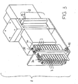
- Assembly unit 8 shown in perspective comprises 20 application units 2 and 20 photodiodes 3.
- Each of the photodiodes 3 is thus arranged such that it can detect the radiation of the additive of an adhesive bead which has been applied by one of the application units 2.
- each of the photodiodes 3 is assigned to an application unit 2.
- the photodiode 3a is assigned to the application unit 2a
- the photodiode 3b is assigned to the application unit 2b, etc.
- the structural unit 8 is designed and arranged in the device such that, in the event of a fault, it can be exchanged for another structural unit 8 'by the method according to the invention.
- FIG. 4 shows a wooden structure 10 in the form of a glued laminated timber, which comprises a plurality of components which are fixedly connected to each other by means of an adhesive connection 20,21.
- some of the adhesive compounds are designed as finger jointing 20 and others as consultancynverklebung 21.
- an adhesive compound 20, 21 contains an adhesive with a luminescent additive that absorbs electromagnetic radiation in a first wavelength range, preferably in the UV range, and in a second wavelength range, preferably between 200 nm and 800 nm, more preferably between 300 nm and 650 nm, most preferably between 410 nm and 480 nm emitted.
- the adhesive compounds 20,21 are irradiated with an authentication light 17, which emits an excitation radiation in the first wavelength range. If the adhesive compound contains an adhesive with the additive, this absorbs the excitation radiation and emits light in the second wavelength range. This emitted light is optionally detected by an authentication sensor 16.
Landscapes
- Chemical & Material Sciences (AREA)
- Organic Chemistry (AREA)
- Engineering & Computer Science (AREA)
- Life Sciences & Earth Sciences (AREA)
- Manufacturing & Machinery (AREA)
- Wood Science & Technology (AREA)
- Forests & Forestry (AREA)
- Adhesives Or Adhesive Processes (AREA)
- Investigating, Analyzing Materials By Fluorescence Or Luminescence (AREA)
- Joining Of Building Structures In Genera (AREA)
- Veneer Processing And Manufacture Of Plywood (AREA)
Description
- Die vorliegende Erfindung betrifft ein Verfahren zum Verbinden mindestens zweier Bauteile, eine Vorrichtung zum Auftragen von Klebstoff auf ein Bauteil sowie ein Verfahren zum Austauschen und/oder Umrüsten einer bestehenden Vorrichtung, gemäss den Oberbegriffen der unabhängigen Patentansprüche.
- Beim Verbinden von Bauteilen mittels Klebstoff ist es insbesondere im konstruktiven Holzbau von essentieller Wichtigkeit, dass der Klebstoff in ausreichender Menge und hinreichender Verteilung auf die Bauteile aufgetragen wird, damit die verbundene Konstruktion eine ausreichende Stabilität gewährleistet.
- Es ist bekannt, den Auftrag von Klebstoff auf Bauteile, etwa auf Holzbauteile, optisch zu überwachen. In
DE 4305991 A1 ist etwa ein Verfahren zur Überwachung des Leimauftrags dargestellt, bei dem die Überwachung mittels Farbzeilenkameras realisiert wird. Die Farbzeilenkameras werden auf mit Klebstoff beschichtete Keilzinken eines Holzbauteils gerichtet und ermöglichen die Feststellung, welche Bereiche der Keilzinken von Klebstoff bedeckt sind. Die Beschichtung geschieht mit Hilfe einer Auftragekopfes mit Austrittsdüsen. Weitere Details zum Auftragsverfahren sind in diesem Dokument jedoch nicht definiert. - Nachteilig ist hierbei die grossflächige Überwachung des Auftrags. Insbesondere ist keine unmittelbare Lokalisierung einer möglichen Ursache für einen fehlerhaften Auftrag möglich. Weiterhin nachteilig ist die Tatsache, dass die Vorrichtung aufgrund der Kameras und der nötigen Bildverarbeitung baulich sehr aufwändig ist. Weiterhin ist die Kombination aus Kameras und Bildverarbeitung selbst störungsanfällig.
- Das Dokument
DE 10 2004 021 573 offenbart ein Inline-Kleberüberwachungssystem und ein Verfahren zur Überwachung von Kleberraupen und zur Kantenerkennung. Das Kleberüberwachungssystem enthält als Sensor einen Kamera- oder CCD-Chip. - Im Dokument
EP 1 025 968 sind ein Verfahren und eine Einrichtung zur Leimerkennung offenbart. Auch dieses Dokument beschreibt die Leimerkennung mittels einer Kamera. - Es ist daher eine Aufgabe der Erfindung, die Nachteile des Bekannten zu überwinden und insbesondere ein weniger störanfälliges und einfacheres Verfahren bereitzustellen, welches zudem eine unmittelbare Lokalisierung einer möglichen Ursache eines fehlerhaften Auftrages erlaubt.
- Erfindungsgemäss wird diese Aufgabe durch ein Verfahren gemäß Anspruch 1 zum Verbinden mindestens zweier Bauteile gelöst, welches die folgenden Schritte umfasst:
- a) Auftragen mindestens einer Klebstoffraupe auf mindestens eines der Bauteile mittels einer Auftragseinheit;
- b) Überwachung des Auftrags der Klebstoffraupe mittels mindestens einer Photodiode, welche der Klebstoffraupe und/oder der Auftragseinheit zugeordnet ist;
- c) Verbinden der Bauteile durch Inkontaktbringen, vorzugsweise Zusammenpressen der Bauteile.
- Die Auftragseinheit ist an sich bekannt und kann etwa eine Düse enthalten. Mindestens eine Photodiode ist der mindestens einen Klebstoffraupe und/oder der mindestens einen Auftragseinheit zugeordnet. Insbesondere überwacht die Photodiode die Klebstoffraupe, welche mittels derjenigen Auftragseinheit aufgetragen wurde, dem die Photodiode zugeordnet ist. Vorzugsweise überwacht die Photodiode ausschliesslich den ordnungsgemässen Auftrag dieser einen Klebstoffraupe.
- Erfindungsgemäss wird als Klebstoff ein Klebstoff mit einem lumineszierenden Additiv verwendet. Insbesondere kann es sich um ein fluoreszierendes Additiv handeln. Die Photodiode detektiert hierbei die von dem Additiv emittierte elektromagnetische Strahlung, insbesondere sichtbares Licht. Dies gestattet es, die für das Additiv charakteristische Strahlung zu detektieren und sie insbesondere von Störlicht wie etwa Streulicht zu unterscheiden, was zu einer definierteren und sichereren Überwachung des Auftrags führt.
- Das erfindungsgemässe Verfahren ermöglicht die unmittelbare Lokalisierung einer möglichen Ursache für einen fehlerhaften Klebstoffauftrag. Fällt beispielsweise eine der Auftragseinheiten aus oder bewirkt sie einen unregelmässigen Auftrag, so wird dies mittels der ihr oder der Klebstoffraupe zugeordneten Photodiode festgestellt. Dies ermöglicht die schnelle und einfache Lokalisierung einer möglichen Fehlerquelle.
- Bevorzugt wird die Überwachung des Auftrags direkt nach dem Auftrag und noch vor dem Verbinden der Bauteile durchgeführt, so dass ein frühzeitiges Erkennen einer allfälligen Störung ermöglicht ist.
- Es ist selbstverständlich ebenso denkbar, dass eine oder mehrere Photodioden die Klebstoffraupen von jeweils mehreren Auftragseinheiten überwachen. Diese Variante sollte allerdings nur für solche Verbindungsstellen gewählt werden, die vergleichsweise nur geringe Kräfte aufzunehmen haben.
- Alternativ oder zusätzlich ist es möglich, dass mehrere der Photodioden eine einzelne Klebstoffraupe überwachen, welche von einer Auftragseinheit aufgetragen wurde. Dadurch kann an betonders kritischen Verbindungsstellen durch eine redundante Überwachung die Qualität des Auftrages mit noch grösserer Sicherheit garantiert werden.
- Bei den Bauteilen kann es sich insbesondere um Holzbauteile handeln. Das Verbinden der Bauteile im Verfahrensschritt c) geschieht vorzugsweise durch Zusammenpressen der Bauteile.
- Bevorzugt wird die Überwachung des Auftrags kontinuierlich durchgeführt. Unter einer kontinuierlichen Überwachung wird hierbei auch verstanden, dass die Überwachung in regelmässigen oder unregelmässigen Zeitabständen erfolgen kann. Dabei kann die Überwachung für alle Photodioden gleichzeitig, zyklisch oder in einer unregelmässigen Reihenfolge geschehen.
- Gemäss einer zusätzlichen Weiterbildung wird der Aufnahmebereich der Photodiode (also die Klebstoffraupe) mit einer Anregungsstrahlung bestrahlt. Unter dem Aufnahmebereich wird hierbei derjenige Raumbereich verstanden, auf den die Photodiode ausgerichtet ist. Bei der Anregungsstrahlung kann es sich insbesondere um UV-Licht handeln.
- Besonders bevorzugt ist die Anregungsstrahlung auf den Klebstoff abgestimmt. Insbesondere kann die Anregungsstrahlung in einem oder mehreren Wellenlängenbereichen erfolgen, in dem oder denen das lumineszierende Additiv Strahlung absorbiert, vorzugsweise ein Absorptionsmaximum aufweist.
- Weiter bevorzugt ist die Photodiode auf den Klebstoff und/oder die Anregungsstrahlung abgestimmt. Insbesondere kann die Photodiode unter anderem oder ausschliesslich elektromagnetische Strahlung in dem oder den Wellenlängenbereichen detektieren, in dem oder denen das lumineszierende Additiv emittiert.
- Vorzugsweise detektiert die Photodiode die elektromagnetische Strahlung, die das Additiv bei oder nach der Bestrahlung mit der Anregungsstrahlung emittiert. Dies garantiert die Überwachung unter sehr wohldefinierten Bedingungen, die unanfällig gegenüber äusseren Einflüssen ist. Weiterhin ist es denkbar, dass die Anregungsstrahlung in ihrer Intensität pulsiert. Durch den Vergleich der detektierten Strahlung bei verschiedenen Intensitäten sind äussere Einflüsse noch effektiver eliminierbar.
- Es ist im Rahmen der Erfindung vorstellbar, dass mittels mehrerer Auftragseinheiten voneinander verschiedene Klebstoffe auftragen werden. Alternativ oder zusätzlich können verschiedene Photodioden und/oder verschiedene Anregungsstrahlungen verwendet werden, welche gegebenenfalls in der beschriebenen Weise aufeinander abgestimmt sind.
- Erfindungsgemäß gibt mindestens eine Photodiode bei Vorliegen einer irregulären Betriebsbedingung ein Fehlersignal aus, nämlich bei einem vollständig oder teilweise fehlenden Auftrag. Das Fehlersignal kann dabei etwa ein elektrisches Signal sein.
- Bevorzugt wird bei Vorliegen eines Fehlersignals ein Warnsignal ausgegeben, welches etwa optischer und/oder akustischer Natur sein kann. Dabei ist es denkbar, dass das Warnsignal bereits dann ausgegeben wird, wenn nur eine einzige Photodiode ein Fehlersignal ausgibt. Alternativ ist es denkbar, dass das Warnsignal nur dann ausgegeben wird, wenn eine vordefinierte Mindestanzahl von Photodioden gleichzeitig oder innerhalb eines vordefinierten Zeitintervalls ein Fehlersignal ausgibt.
- Alternativ oder zusätzlich zu dem Warnsignal kann bei Vorliegen des Fehlersignals das Verfahren automatisch unterbrochen werden. Insbesondere kann bei Vorliegen eines Fehlersignals von einer oder mehreren Photodioden das Auftragen durch sämtliche Auftragseinheiten unterbrochen werden. Weiterhin kann das Verbinden der Bauteile unterbrochen werden.
- Die Ausgabe eines Warnsignals und die Unterbrechung des Verfahrens garantieren eine qualitativ hochwertige und sichere Verbindung der einzelnen Bauteile miteinander. Insbesondere ermöglichen es diese Massnahmen, dass das Verfahren nicht kontinuierlich durch einen Menschen überwacht werden muss.
- Gemäss einer Weiterentwicklung des Verfahrens wird der Klebstoff berührungslos aufgetragen. Dies garantiert einen gleichmässigeren Auftrag und verhindert etwa ein Verstopfen der Auftragseinheit.
- Ein weiterer Aspekt der Erfindung betrifft eine Vorrichtung zum Auftragen von Klebstoff auf ein Bauteil. Die Vorrichtung umfasst mindestens eine Auftragseinheit zum Auftragen von Klebstoffraupen auf ein Bauteil sowie mindestens eine Photodiode zur Überwachung des Auftrags der Klebstoffraupe auf das Bauteil sowie Leuchtmittel zur Bestrahlung der Klebstoffraupen, die Strahlung im UV-Bereich emittieren. Erfindungsgemäss ist wenigstens einer Auftragseinheit eine Photodiode zugeordnet.
- Insbesondere sind die Auftragseinheit und die Photodiode derart angeordnet, dass die Klebstoffraupe, welche mittels der Auftragseinheit aufgetragen wurde, von der Photodiode detektierbar ist. Bevorzugt ist die Photodiode derart angeordnet, dass sein Aufnahmebereich in vorzugsweise unmittelbarer Nähe der Auftragseinheit liegt. Somit ist ein frühzeitiges Erkennen einer allfälligen Störung ermöglicht.
- Bevorzugt handelt es sich bei der Vorrichtung um eine Vorrichtung für das Auftragen von Klebstoff auf Fügeteile und für das Verbinden der Fügeteile. Insbesondere kann es sich um eine Keilzinkenanlage handeln. Bevorzugt sind die Auftragseinheiten und/oder Photodioden innerhalb der Vorrichtung bewegbar. Insbesondere sind sie relativ zu Haltemitteln bewegbar, in welchen ein Bauteil haltbar ist. Die Vorrichtung kann weiterhin Mittel zum Transport der Bauteile und/oder Verbindungseinrichtungen wie etwa Presseinrichtungen enthalten. Insbesondere ist diese Vorrichtung zur Durchführung des erfindungsgemässen Verfahrens zum Verbinden von Bauteilen geeignet.
- Es ist denkbar, dass mindestens eine Photodiode derart angeordnet ist, dass die Klebstoffraupen mehrerer Auftragseinheiten in seinem Aufnahmebereich liegen. Somit kann diese Photodiode das Auftragen mehrere Klebstoffraupen überwachen. Diese Variante kann zwecks einer Kostenersparnis und/oder einer baulichen Vereinfachung für solche Verbindungsstellen gewählt werden, die vergleichsweise nur geringe Kräfte aufzunehmen haben.
- Alternativ oder zusätzlich ist es möglich, dass eine Gruppe von Photodioden derart angeordnet ist, dass die Klebstoffraupe einer einzelnen Auftragseinheit in jedem ihrer Aufnahmebereiche liegt. Dadurch kann an besonders kritischen Verbindungsstellen durch eine redundante Überwachung die Qualität des Auftrages mit noch grösserer Sicherheit garantiert werden.
- Erfindungsgemäß ist mindestens eine der Photodioden derart ausgebildet, dass bei Vorliegen einer irregulären Betriebsbedingung ein Fehlersignal ausgebbar ist, nämlich bei einem fehlenden Auftrag. Das Fehlersignal kann dabei etwa elektrischer Natur sein.
- Bevorzugt ist die Vorrichtung aufgrund eines Signals, insbesondere eines Fehlersignals, mindestens einer der Photodioden steuerbar. Besonders bevorzugt ist mindestens eine der Auftragseinheiten, vorzugsweise alle Auftragseinheiten, bei Vorliegen eines Signals vorzugsweise automatisch deaktivierbar. Dies ermöglicht die Unterbrechung des Klebstoffauftrags, sobald eine irreguläre Betriebsbedingung vorliegt. Alternativ oder zusätzlich können aufgrund des Signals die Mittel zum Transport der Bauteile und/oder die Verbindungseinrichtung, insbesondere die Presseinrichtung, deaktiviert werden. Somit wird verhindert, dass Bauteile mit irregulärem Klebstoffauftrag miteinander verbunden werden.
- Darüber hinaus ist es denkbar, dass die Vorrichtung eine Warneinrichtung aufweist, welche bei Vorliegen eines Fehlersignals aktivierbar ist. Bei der Warneinrichtung kann es sich beispielsweise um einen Bildschirm, eine Warnleuchte oder eine Sirene handeln.
- Die Vorrichtung weist Leuchtmittel auf, mittels deren die Klebstoffraupen bestrahlbar sind. Bei der Durchführung des erfindungsgemässen Verfahrens mit der Vorrichtung kann somit ein Klebstoff mit einem lumineszierenden, insbesondere fluoreszierenden Additiv verwendet werden, der geeignet ist, die elektromagnetische Strahlung der Leuchtmittel zu absorbieren. Dabei können die Leuchtmittel eine oder mehrere Leuchten umfassen. Die Leuchten können jeweils einer Photodiode zugeordnet sein und derart angeordnet sein, dass jeweils nur eine Klebstoffraupe bestrahlbar ist. Insbesondere können eine Photodiode und eine Leuchte sowohl Teil eines integralen Bauteils sein als auch eine integrale Baueinheit bilden. Alternativ kann mindestens eine der Leuchten derart angeordnet sein, dass mehrere Klebstoffraupen bestrahlbar sind. Bei hinreichend langer Abregungszeit des lumineszierenden Additivs, insbesondere bei phosphoreszierenden Additiven, ist es nicht unbedingt erforderlich, dass sich der durch die Leuchten bestrahlte Bereich und der Aufnahmebereich der Photodiode überlappen. Weiterhin ist es bevorzugt, dass die Leuchtmittel innerhalb der Vorrichtung bewegbar sind. Insbesondere können sie relativ zu den Haltemitteln bewegbar sein.
- Es ist vorstellbar, dass mittels mehrerer Auftragseinheiten voneinander verschiedene Klebstoffe auftragen werden. Alternativ oder zusätzlich können verschiedene Photodioden und/oder verschiedene Anregungsstrahlungen verwendet werden, welche optional im oben erläuterten Sinne aufeinander abgestimmt sind.
- Bevorzugt ist mindestens eine Auftragseinheit derart angeordnet, dass eine Klebstoffraupe berührungslos auf das Bauteil auftragbar ist. Dies garantiert einen gleichmässigeren Auftrag und verhindert etwa ein Verstopfen der Auftragseinheit.
- Ein weiterer, nicht erfindungsgemässer Aspekt der Offenbarung betrifft eine insbesondere integrale Baueinheit, die insbesondere für die erfindungsgemässe Vorrichtung zum Auftragen von Klebstoff geeignet ist. Die Baueinheit umfasst
- a) mindestens eine Auftragseinheit zum Auftragen von Klebstoffraupen auf ein Bauteil und mindestens eine Photodiode, zur Überwachung des Auftrags der Klebstoffraupe; oder
- b) mindestens eine Auftragseinheit zum Auftragen von Klebstoffraupen auf ein Bauteil und Leuchtmittel zur Bestrahlung von Klebstoffraupen, die insbesondere Strahlung im UV-Bereich emittieren; oder
- c) Leuchtmittel zur Bestrahlung von Klebstoffraupen, die insbesondere Strahlung im UV-Bereich emittieren, und mindestens eine Photodiode zur Überwachung des Auftrags einer Klebstoffraupe.
- Einerseits kann eine derartige Baueinheit zum Austausch einer defekten Baueinheit in einer Vorrichtung verwendet werden. Weiterhin kann die Baueinheit benutzt werden, um eine herkömmliche Vorrichtung zum Auftragen von Klebstoff zu einer erfindungsgemässen Vorrichtung umzurüsten.
- Die einzelnen Elemente der oben aufgeführten Varianten können selbstverständlich eine oder mehrere der weiter oben beschriebenen Weiterbildungen aufweisen. Beispielsweise könnte eine Photodiode in einer Baueinheit gemäss einer der Varianten a) oder c) derart ausgebildet sein, dass bei Vorliegen einer irregulären Betriebsbedingung ein Fehlersignal ausgebbar ist.
- Darüber hinaus betrifft die Erfindung ein Verfahren zum Austauschen und/oder Umrüsten einer bestehenden Vorrichtung. Erfindungsgemäss umfasst dieses Verfahren das Anbringen mindestens einer Photodiode und eines Leuchtmittels, welches Strahlung um UV-Bereich emittiert, insbesondere durch eine Baueinheit wie vorstehend dargelegt.
- Ein weiterer, nicht erfindungsgemässer Aspekt der Offenbarung betrifft einen Klebstoff, insbesondere einen Polyurethan-Klebstoff, enthaltend wenigstens ein, vorzugsweise eine Mischung von zwei oder mehreren lumineszierenden, insbesondere fluoreszierenden Additiven, wobei der Klebstoff eine derartige Viskosität und Standfestigkeit aufweist, dass bei 20 °C und 1013 hPa eine Klebstoffraupe mit einem Durchmesser von 4 mm auf ein ebenes Holzsubstrat auftragbar ist und dort während mindestens 4 Minuten in der Waagerechten im Wesentlichen formstabil lagerbar ist.
- Besonders bevorzugt ist das lumineszierende, insbesondere fluoreszierende Additiv mit UV-Strahlung anregbar und emittiert Strahlung im Wellenlängenbereich von 200 nm bis 800 nm, vorzugsweise im Wellenlängenbereich von 300 nm bis 650 nm, besonders bevorzugt im Wellenlängenbereich von 410 nm bis 480 nm.
- Geeignete, insbesondere fluoreszierende Additive sind dem Fachmann geläufig (vergl. Ullman's Encyclopedia of Industrial Chemistry Vol. A18 (5th Edition) pp. 153 - 167; hinsichtlich geeigneter Fluoreszenz-Additive in die vorliegende Anmeldung durch Bezugnahme eingeschlossen), bspw. Distyrylbenzene, Distyrylbiphenyl und Divinylstilbene, Triazinylaminostilbene, Benzoxazole wie HASTALUXV KCB (2,2-(1,4-Naphthalenediyl)bis-benzoxazole), die EASTOBRITE® Produktlinie von Eastman Chemical, insbesondere EASTOBRITE® OB-1, (2,2'-(1,2-ethenediyldi-4,1-phenylene)bisbenzoxazole), Stilbenylbenzoxazole und - bis(benzoxazole), Furane und Benzo[b]furane, wie Bis(benzo[b]furan-2-yl)biphenyle und Benzimidazole, wie kationische Benzimidazole, 1,3, Diphenyl-2-pyrazoline, Coumarine, Naphtalimide und 1,3,5-Triazin-2-yl-Derivate, Fluorescein® und "FLUORESCENT BRIGHTENER 28 FREE ACID fluorescent dye" (Sigma-Aldrich), Benzoxazol-Derivate wie bspw. Uvitex® OB (2,5-(di-5-tert-butylbenzoyl)thiophenate) (Ciba Specialty Chemicals), Blankophor® CA 4410 (Bayer), Pyrene wie bspw. Aminocoumarin-Konjugate, insbesondere Dialkylaminocoumarinpyrene, z.B. ALEXA FLUOR® 350 (Carbonsäuresuccinimidylester) und AMCA-X Farbstoffe (Succinimidylester), Naphtalinderivate wie z.B. N,N-Dimethylamino-5-propionylnaphthalin, RHODAMINE RED® oder TEXAS RED-X® (Molecular Probes), etc. Ganz besonders bevorzugt ist in diesem Zusammenhang Uvitex® OB (2,5-(di-5-tert-butylbenzoyl)thiophenate) (Ciba Specialty Chemicals).
- Selbstverständlich können auch Gemische insbesondere der vorstehend genannten Additive eingesetzt werden.
- Die Fluoreszenz-Additive werden dem Klebstoff in einer Menge von etwa 0.001 bis etwa 2%, vorzugsweise von etwa 0.001 bis etwa 0.1%, besonders bevorzugt von etwa 0.002% bis etwa 0.01% beigegeben, bezogen auf das Gesamtgewicht des Klebstoffs.
- Der Klebstoff kann zum Verbinden von Bauteilen verwendet werden. Insbesondere kann er im erfindungsgemässen Verfahren zum Verbinden und/oder der erfindungsgemässen Vorrichtung eingesetzt werden.
- Bevorzugt ist dabei das Additiv des Klebstoffs auf das Verfahren und/oder die Vorrichtung abgestimmt, wie bereits ausgeführt würde. Beispielsweise könnte das Additiv derart ausgewählt sein, dass elektromagnetische Strahlung in einem Wellenlängenbereich absorbierbar ist, welcher einer Anregungsstrahlung entspricht.
- Ein weiterer, nicht erfindungsgemässer Aspekt der Offenbarung betrifft eine Holzkonstruktion, insbesondere ein Brettschichtholz, welches mehrere Bauteile umfasst, welche mit dem erfindungsgemässen Klebstoff verbunden sind.
- Als weiteren, nicht erfindungsgemässen Aspekt betrifft die Offenbarung ein Verfahren zur Authentifizierung einer Holzkonstruktion, welche mindestens eine Klebstoffverbindung umfasst. Insbesondere kann die Holzkonstruktion eine Klebstoffverbindung mit einem erfindungsgemässen Klebstoff enthalten. Das Verfahren zur Authentifizierung enthält die folgenden Schritte:
- a) Detektierung der von der Klebstoffverbindung emittierten Strahlung, insbesondere Detektierung eines Teils des Spektrums der emittierten Strahlung;
- b) Vergleich der detektierten Strahlung mit mindestens einem vordefinierten Kriterium.
- Dabei kann es sich bei dem vordefinierten Kriterium etwa das Vorliegen der Emission mit einer vordefinierten Intensität in einem festgelegten Wellenlängenbereich handeln.
- Das Verfahren ermöglicht es, einen in einer vorgegebenen Holzkonstruktion enthaltenen Klebstoff zu identifizieren. Um etwa zu überprüfen, ob eine Klebstoffverbindung in einer Holzkonstruktion einen Klebstoff mit einem lumineszierenden Additiv enthält, das elektromagnetische Strahlung in einem bestimmten Wellenlängenbereich emittiert, wird gemäss dem Verfahren die von der Klebstoffverbindung emittierte Strahlung detektiert. Wird eine vordefinierte Intensität in dem Wellenlängenbereich überschritten, so dient dies als ein Indiz für das Vorliegen des Additivs und damit für das Vorliegen des Klebstoffs. Die Emission kann als Herkunftsnachweis des Klebstoffs herangezogen werden. In besonders bevorzugten Ausführungsformen wird im Rahmen dieses Aspekts der Offenbarung ein Klebstoff mit einem Gemisch zweier oder mehrerer Lumineszenz-Additive verwendet, um den Herkunftsnachweis komplexer und somit nachahmungssicherer zu machen.
- Gemäss einer Weiterentwicklung des Verfahrens zur Authentifizierung wird die Klebstoffverbindung mit einer Anregungsstrahlung bestrahlt. Insbesondere kann die Anregungsstrahlung im UV-Bereich liegen. Dies erweist sich als besonders vorteilhaft, falls das lumineszierende Additiv in einem bestimmten Absorptionswellenlängenbereich Strahlung absorbiert. Bevorzugt ist dabei die Anregungsstrahlung auf diesen Absorptionswellenlängenbereich abgestimmt. Ebenfalls ist es denkbar, dass die Anregungsstrahlung in ihrer Intensität pulsiert. Durch den Vergleich der detektierten Strahlung bei verschiedenen Intensitäten sind äussere Einflüsse noch effektiver korrigierbar.
- Details und weitere Vorteile der Erfindung ergeben sich aus den folgenden Ausführungsbeispielen. Es zeigen:
- Fig. 1
- eine schematische Skizze eines Ausschnitts einer er- findungsgemässen Vorrichtung 1;
- Fig. 2
- eine schematische Skizze derselben Ausschnitts bei Vorliegen einer irregulären Betriebsbedingung;
- Fig. 3
- eine perspektivische Darstellung einer Baueinheit 8;
- Fig. 4
- eine Holzkonstruktion 10 in Form eines Brettschicht- holzes.
- Der in
Figur 1 dargestellte Ausschnitt einer erfindungsgemässen Vorrichtung 1 zeigt eine Baueinheit 8 mit einer als Düse ausgebildeten Auftragseinheit 2, einer Photodiode 3 und Leuchtmitteln 7. Die Auftragseinheit 2 trägt berührungslos einen Klebstoff 5 in Form einer Klebstoffraupe 6 auf ein Bauteil 9 auf, welches von Haltemitteln 11 gehalten wird Das Bauteil 9 weist an einer Seite Keilzinken 18 auf, auf deren Oberseiten 19 die Klebstoffraupe 6 abgelegt wird. Die Baueinheit 8 wird durch Transportmittel 15, welche hier nur schematisch durch zwei Führungsrollen angedeutet sind, in der Bewegungsrichtung B bewegt. Alternativ ist es denkbar und liegt im Rahmen der Erfindung, dass das Bauteil 9 bewegt wird. Die Leuchtmittel 7 bestrahlen die Klebstoffraupe 6 mit einer Anregungsstrahlung der Wellenlänge 360 nm. Der Klebstoff 5 enthält ein lumineszierendes Additiv, welches die Anregungsstrahlung absorbiert. Als Klebstoff wird besonders bevorzugt ein feuchtigkeitshärtender 1-Komponenten-Polyurethanklebstoff folgender Zusammensetzung eingesetzt: - Gemisch von MDI-Präpolymeren mit einem mittleren Molekulargewicht von 400 bis 600 g/Mol: 80-95%, besonders bevorzugt 94%;
- Füllstoffe: 0-15%, besonders bevorzugt 4.2%;
- Rheologiehilfsmittel: 0-3%, besonders bevorzugt 1%;
- Benetzungsmittel: 0-1%, besonders bevorzugt 0.5%;
- Entschäumer: 0-0.3%, besonders bevorzugt 0.2%;
- UV- Additiv: 0.005-0.02%, besonders bevorzugt 0.005%;
- Katalysatoren: 0-2%, besonders bevorzugt 0.1%.
- Die Photodiode 3 ist relativ zur Auftragseinheit 2 derart angeordnet, dass im Wesentlichen nur die von der Auftragseinheit 2 aufgetragene und von den Leuchtmitteln 7 bestrahlte Klebstoffraupe 6 in seinem Aufnahmebereich 4 liegt. Im Sinne der Erfindung ist somit die Photodiode 3 der Auftragseinheit 2 zugeordnet. Die Photodiode 3 kann somit die von der Klebstoffraupe 6 und insbesondere dem darin enthaltenen Additiv emittierte Strahlung detektieren. Im vorliegenden Fall emittiert das Additiv Strahlung im Wellenlängenbereich von 200 nm bis 800 nm, vorzugsweise im Wellenlängenbereich von 300 nm bis 650 nm, besonders bevorzugt im Wellenlängenbereich von 410 nm bis 480 nm.
- Die Photodiode 3 ist über eine Signalleitung 13 mit einer Steuereinheit 12 verbunden, welche ihrerseits über eine Signalleitung 14 mit den Transportmitteln 15 verbunden ist. Die Funktion dieser Bauelemente wird im Zusammenhang mit
Figur 2 erläutert. - Das Vorliegen einer irregulären Betriebsbedingung ist in
Figur 2 dargestellt. In diesem Falle liegt an der Auftragseinheit 2 eine Störung vor, so dass Klebstoffraupe 6 teilweise unterbrochen ist. Infolgedessen detektiert die Photodiode 3 nicht mehr die vom Additiv emittierte Strahlung und gibt somit über die Signalleitung 13 ein Fehlersignal an die Steuereinheit 12 aus. Die Steuereinheit 12 sendet sodann über die Steuerleitung 14 ein Steuersignal an die Transportmittel 15, was zur Unterbrechung der Bewegung der Baueinheit 8 und damit zur Unterbrechung des Verfahrens führt. - Die in
Figur 3 perspektivisch dargestellte Baueinheit 8 umfasst 20 Auftragseinheiten 2 und 20 Photodioden 3. Jede der Photodioden 3 ist also derart angeordnet, dass sie die Strahlung des Additivs einer Klebstoffraupe detektieren kann, welche von jeweils einer der Auftragseinheiten 2 aufgetragen wurde. Im Sinne der Erfindung ist damit jeder der Photodioden 3 einer Auftragseinheit 2 zugeordnet. So ist etwa die Photodiode 3a der Auftragseinheit 2a zugeordnet, die Photodiode 3b ist der Auftragseinheit 2b zugeordnet, etc. - Die Baueinheit 8 ist derart ausgebildet und in der Vorrichtung angeordnet, dass sie im Falle einer Störung durch das erfindungsgemässe Verfahren zum Austausch gegen eine andere Baueinheit 8' austauschbar ist.
- Die
Figur 4 zeigt eine Holzkonstruktion 10 in Form eines Brettschichtholzes, welches mehrere Bauteile umfasst, die mittels einer Klebstoffverbindung 20,21 miteinander fest verbunden sind. Dabei sind einige der Klebstoffverbindungen als Keilzinkenverklebung 20 und andere als Flächenverklebung 21 ausgebildet. Mit Hilfe des Verfahrens zur Authentifizierung soll überprüft werden, ob eine Klebstoffverbindung 20,21 einen Klebstoff mit einem lumineszierenden Additiv enthält, das elektromagnetische Strahlung in einem ersten Wellenlängenbereich, vorzugsweise im UV-Bereich, absorbiert und in einem zweiten Wellenlängenbereich, bevorzugt zwischen 200 nm und 800 nm, besonders bevorzugt zwischen 300 nm und 650 nm, ganz besonders bevorzugt zwischen 410 nm und 480 nm, emittiert. Hierzu werden die Klebstoffverbindungen 20,21 mit einer Authentifizierungsleuchte 17 bestrahlt, die eine Anregungsstrahlung im ersten Wellenlängenbereich aussendet. Falls die Klebstoffverbindung einen Klebstoff mit dem Additiv enthält, absorbiert dieses die Anregungsstrahlung und emittiert Licht im zweiten Wellenlängenbereich. Dieses emittierte Licht wird gegebenenfalls von einem Authentifizierungssensor 16 detektiert.
Claims (8)
- Verfahren zum Verbinden mindestens zweier Bauteile (9), insbesondere Holzbauteile, umfassend die folgenden Schritte:a) Auftragen mindestens einer Klebstoffraupe (6) auf mindestens eines der Bauteile (9) mittels einer Auftragseinheit (2);b) Überwachung des Auftrags der Klebstoffraupe (6) mittels mindestens einer Photodiode (3), welche der aufgetragenen Klebstoffraupe (6) und/oder der Auftragseinheit (2) zugeordnet ist;c) Verbinden der Bauteile (9) durch Inkontaktbringen, vorzugsweise Zusammenpressen der Bauteile (9),dadurch gekennzeichnet, dass
ein Klebstoff (5) mit einem lumineszierenden, insbesondere fluoreszierenden Additiv verwendet wird, und dass die Photodiode (3) die vom lumineszierenden, insbesondere fluoreszierenden Additiv emittierte Strahlung detektiert,
wobei bei fehlendem Auftrag ein Fehlersignal ausgegeben wird. - Verfahren gemäss Anspruch 1, dadurch gekennzeichnet, dass die Klebstoffraupe (6), insbesondere lediglich in einem Aufnahmebereich (4) der Photodiode (3) mit einer Anregungsstrahlung, insbesondere mit UV-Licht bestrahlt wird.
- Verfahren gemäss Anspruch 2, dadurch gekennzeichnet, dass der Aufnahmebereich (4) der Photodiode (3) im Wesentlichen lediglich eine Klebstoffraupe (6) erfasst.
- Verfahren gemäss einem der vorangehenden Ansprüche, dadurch gekennzeichnet, dass
bei Vorliegen des Fehlersignals ein Warnsignal ausgegeben wird und/oder das Verfahren automatisch unterbrochen wird. - Vorrichtung (1) zum Auftragen von Klebstoff (5) auf ein Bauteil (9), vorzugsweise einen Holzwerkstoff, insbesondere zur Durchführung eines Verfahrens gemäss einem der Ansprüche 1 bis 4, umfassend- mindestens eine Auftragseinheit (2) zum Auftragen von Klebstoffraupen (6) auf ein Bauteil (9),- mindestens eine Photodiode (3) zur Überwachung des Auftrags der Klebstoffraupe (6) auf das Bauteil (9),- Leuchtmittel (7) zur Bestrahlung der Klebstoffraupen (6), die Strahlung im UV-Bereich emittieren,dadurch gekennzeichnet, dass wenigstens einer Auftragseinheit (2) eine Photodiode (3) zugeordnet ist,
wobei bei fehlendem Auftrag ein Fehlersignal ausgebbar ist. - Vorrichtung (1) gemäss Anspruch 5, dadurch gekennzeichnet, dass es sich um eine Vorrichtung (1) für das Auftragen von Klebstoff (5) auf Fügeteile und für das Verbinden der Fügeteile, insbesondere um eine Keilzinkenanlage handelt.
- Vorrichtung (1) gemäss einem der Ansprüche 5 und 6, dadurch gekennzeichnet, dass die Vorrichtung (1) aufgrund des Fehlersignal steuerbar ist, insbesondere mindestens eine der Auftragseinheiten (2) automatisch deaktivierbar ist.
- Verfahren zum Austauschen und/oder Umrüsten einer bestehenden Vorrichtung zum Auftragen von Klebstoff (5) als Klebstoffraupe auf ein Bauteil (9), umfassend das Anbringen mindestens einer Photodiode (3) und eines Leuchtmittels (7), welches Strahlung um UV-Bereich emittiert.
Priority Applications (3)
| Application Number | Priority Date | Filing Date | Title |
|---|---|---|---|
| AT07107166T ATE502986T1 (de) | 2007-04-27 | 2007-04-27 | Verfahren zum verbinden von (holz-)bauteilen |
| DE502007006770T DE502007006770D1 (de) | 2007-04-27 | 2007-04-27 | Verfahren zum Verbinden von (Holz-)Bauteilen |
| EP07107166.6A EP1985676B2 (de) | 2007-04-27 | 2007-04-27 | Verfahren zum Verbinden von (Holz-)Bauteilen |
Applications Claiming Priority (1)
| Application Number | Priority Date | Filing Date | Title |
|---|---|---|---|
| EP07107166.6A EP1985676B2 (de) | 2007-04-27 | 2007-04-27 | Verfahren zum Verbinden von (Holz-)Bauteilen |
Publications (3)
| Publication Number | Publication Date |
|---|---|
| EP1985676A1 EP1985676A1 (de) | 2008-10-29 |
| EP1985676B1 EP1985676B1 (de) | 2011-03-23 |
| EP1985676B2 true EP1985676B2 (de) | 2019-03-20 |
Family
ID=38475908
Family Applications (1)
| Application Number | Title | Priority Date | Filing Date |
|---|---|---|---|
| EP07107166.6A Active EP1985676B2 (de) | 2007-04-27 | 2007-04-27 | Verfahren zum Verbinden von (Holz-)Bauteilen |
Country Status (3)
| Country | Link |
|---|---|
| EP (1) | EP1985676B2 (de) |
| AT (1) | ATE502986T1 (de) |
| DE (1) | DE502007006770D1 (de) |
Families Citing this family (6)
| Publication number | Priority date | Publication date | Assignee | Title |
|---|---|---|---|---|
| DE102008056344A1 (de) * | 2008-11-07 | 2010-05-12 | Wilhelm Karmann Gmbh | Verfahren zur Herstellung einer Klebenaht an einem Verdeckbezug eines Kraftfahrzeuges |
| GB201004458D0 (en) | 2010-03-17 | 2010-05-05 | Dynea Oy | Contactless application of an adhesive |
| DE102012222377A1 (de) * | 2012-12-06 | 2014-07-10 | Bayerische Motoren Werke Aktiengesellschaft | Verfahren zur optischen Überprüfung einer Klebestelle |
| DE102021102830A1 (de) | 2021-02-08 | 2022-08-11 | Ats Automation Tooling Systems Gmbh | Verfahren und Vorrichtung zur Überprüfung einer Klebstoffverbindung zwischen einer Hohlnadel oder Kanüle und einem Halteteil |
| DE102022124059A1 (de) * | 2022-09-20 | 2024-03-21 | Bayerische Motoren Werke Aktiengesellschaft | System und Verfahren zur optischen Bewertung eines Auftrags wenigstens einer pastösen Masse auf einem Bauteil sowie ein Fahrzeug |
| AT528558A1 (de) | 2024-07-19 | 2026-02-15 | Fill Gmbh | Brettlamellenfügevorrichtung zum Verbinden von einzelnen Brettlamellen zu einem Lamellenteppich, sowie ein Verfahren zum Herstellen eines Verbundbauteiles mit einzelnen Brettlamellen |
Citations (1)
| Publication number | Priority date | Publication date | Assignee | Title |
|---|---|---|---|---|
| US7178896B2 (en) † | 2003-01-29 | 2007-02-20 | Hewlett-Packard Development Company, L.P. | Article of manufacture including a two-part adhesive with a fluorescent dye and method of making |
Family Cites Families (6)
| Publication number | Priority date | Publication date | Assignee | Title |
|---|---|---|---|---|
| DE4305991C1 (de) | 1993-02-26 | 1994-06-01 | Grecon Greten Gmbh & Co Kg | Verfahren zur Überwachung des Leimauftrags bei der Herstellung einer verleimten Keilzinkenverbindung zweier Hölzer |
| US5666325A (en) * | 1995-07-31 | 1997-09-09 | Nordson Corporation | Method and apparatus for monitoring and controlling the dispensing of materials onto a substrate |
| DE59910987D1 (de) | 1999-02-06 | 2004-12-09 | M T E Marketing Technik Engine | Verfahren und Einrichtung zur Leimerkennung |
| FR2802460B1 (fr) * | 1999-12-21 | 2005-06-24 | Rene Bloch | Procede de fabrication d'un produit en bois lamelle-colle et produit ainsi obtenu |
| DE102004021573A1 (de) | 2004-05-03 | 2005-12-01 | Adam Opel Ag | Inline-Kleberüberwachungssystem und Verfahren zur Überwachung von Kleberraupen und zur Kantenerkennung |
| DE102004022232A1 (de) * | 2004-05-04 | 2005-12-01 | Infineon Technologies Ag | Viskoses Klebematerial zur Befestigung elektronischer Bauelemente |
-
2007
- 2007-04-27 EP EP07107166.6A patent/EP1985676B2/de active Active
- 2007-04-27 DE DE502007006770T patent/DE502007006770D1/de active Active
- 2007-04-27 AT AT07107166T patent/ATE502986T1/de active
Patent Citations (1)
| Publication number | Priority date | Publication date | Assignee | Title |
|---|---|---|---|---|
| US7178896B2 (en) † | 2003-01-29 | 2007-02-20 | Hewlett-Packard Development Company, L.P. | Article of manufacture including a two-part adhesive with a fluorescent dye and method of making |
Also Published As
| Publication number | Publication date |
|---|---|
| ATE502986T1 (de) | 2011-04-15 |
| EP1985676A1 (de) | 2008-10-29 |
| EP1985676B1 (de) | 2011-03-23 |
| DE502007006770D1 (de) | 2011-05-05 |
Similar Documents
| Publication | Publication Date | Title |
|---|---|---|
| EP1985676B1 (de) | Verfahren zum Verbinden von (Holz-)Bauteilen | |
| DE102009039029B4 (de) | Verfahren zum Fügen von mindestens zwei Bauteilen unter Verwendung einer dualhärtenden Klebstoffzusammensetzung | |
| DE112007002751T5 (de) | UV-Bestrahlungsvorrichtung und UV-Bestrahlungsverfahren | |
| DE112010005248T5 (de) | Modulare led-array-lichtquellen von hoher dichte | |
| DE102015115894A1 (de) | Zeugnisfähige Befestigungseinrichtungen und verwandte Systeme und Verfahren | |
| EP3108177A1 (de) | Beleuchtungsvorrichtung mit primärlichtquelle und leuchtstoffvolumen | |
| DE102020203506A1 (de) | Wellenlängenumwandlungselement, lichtquellenvorrichtung und beleuchtungsvorrichtung | |
| EP2846146A1 (de) | Bewitterungsprüfung mit mehreren unabhängig voneinander ansteuerbaren Strahlungsquellen | |
| EP1502859B1 (de) | Vorrichtung und Verfahren zum Überprüfen eines aufgeklebten Gegenstandes | |
| DE4305991C1 (de) | Verfahren zur Überwachung des Leimauftrags bei der Herstellung einer verleimten Keilzinkenverbindung zweier Hölzer | |
| DE102016102901B4 (de) | Verfahren zum Verbinden von Komponenten unter Verwendung eines mit Energiestrahlen härtbaren Klebstoffs | |
| DE112015004032T5 (de) | Led-dentallichtquelle mit veränderlicher chromatizität und verfahren | |
| EP2473090B1 (de) | Medizinische leuchte für hintergrundlicht und anregungslicht | |
| EP3394503B1 (de) | Scheinwerfer für fahrzeuge mit zumindest einem laser-lichtmodul | |
| EP2929324A1 (de) | Verfahren zur optischen überprüfung einer klebestelle | |
| WO2021004976A1 (de) | Komprimierbarer, uv- oder thermisch aktivierbarer (semi-) struktureller klebefilm mit farbumschlag jeweils nach aktivierung und aushärtung | |
| WO2007113287A1 (de) | Verwendung der infrarot-thermographie als mittel zur bestimmung des aushärtungsverlaufes einer zweikomponentigen zusammensetzung | |
| DE10251775A1 (de) | Verfahren zum Fügen von Plattenelementen einer Brennstoffzelleneinheit | |
| EP1025968B1 (de) | Verfahren und Einrichtung zur Leimerkennung | |
| EP1308477A1 (de) | Lichthärtendes Kunststoffmaterial mit Indikator zur Anzeige des Aushärtungsgrades | |
| WO2020119898A1 (de) | Wickel- und stanzbarer klebender film | |
| EP3788112B1 (de) | Wickel- und stanzbares klebeband zur selektiven uv-aktivierung | |
| EP2191324A1 (de) | Lichtemittierendes flächenelement und verfahren zum herstellen eines lichtemittierenden flächenelementes | |
| DE102020122217B4 (de) | Beleuchtungsvorrichtung mit Lichtleitfasermodul und Verfahren zur Herstellung eines Lichtleitfasermoduls | |
| EP1234648A1 (de) | Verfahren und Vorrichtung zur Voraktivierung kationisch polymerisierender Massen |
Legal Events
| Date | Code | Title | Description |
|---|---|---|---|
| PUAI | Public reference made under article 153(3) epc to a published international application that has entered the european phase |
Free format text: ORIGINAL CODE: 0009012 |
|
| AK | Designated contracting states |
Kind code of ref document: A1 Designated state(s): AT BE BG CH CY CZ DE DK EE ES FI FR GB GR HU IE IS IT LI LT LU LV MC MT NL PL PT RO SE SI SK TR |
|
| AX | Request for extension of the european patent |
Extension state: AL BA HR MK RS |
|
| RAP1 | Party data changed (applicant data changed or rights of an application transferred) |
Owner name: PURBOND AG |
|
| 17P | Request for examination filed |
Effective date: 20090314 |
|
| 17Q | First examination report despatched |
Effective date: 20090504 |
|
| AKX | Designation fees paid |
Designated state(s): AT BE BG CH CY CZ DE DK EE ES FI FR GB GR HU IE IS IT LI LT LU LV MC MT NL PL PT RO SE SI SK TR |
|
| GRAP | Despatch of communication of intention to grant a patent |
Free format text: ORIGINAL CODE: EPIDOSNIGR1 |
|
| GRAS | Grant fee paid |
Free format text: ORIGINAL CODE: EPIDOSNIGR3 |
|
| GRAA | (expected) grant |
Free format text: ORIGINAL CODE: 0009210 |
|
| AK | Designated contracting states |
Kind code of ref document: B1 Designated state(s): AT BE BG CH CY CZ DE DK EE ES FI FR GB GR HU IE IS IT LI LT LU LV MC MT NL PL PT RO SE SI SK TR |
|
| REG | Reference to a national code |
Ref country code: GB Ref legal event code: FG4D Free format text: NOT ENGLISH |
|
| REG | Reference to a national code |
Ref country code: CH Ref legal event code: EP |
|
| REG | Reference to a national code |
Ref country code: IE Ref legal event code: FG4D |
|
| REG | Reference to a national code |
Ref country code: CH Ref legal event code: NV Representative=s name: HEPP WENGER RYFFEL AG |
|
| REF | Corresponds to: |
Ref document number: 502007006770 Country of ref document: DE Date of ref document: 20110505 Kind code of ref document: P |
|
| REG | Reference to a national code |
Ref country code: DE Ref legal event code: R096 Ref document number: 502007006770 Country of ref document: DE Effective date: 20110505 |
|
| REG | Reference to a national code |
Ref country code: NL Ref legal event code: VDEP Effective date: 20110323 |
|
| PG25 | Lapsed in a contracting state [announced via postgrant information from national office to epo] |
Ref country code: SE Free format text: LAPSE BECAUSE OF FAILURE TO SUBMIT A TRANSLATION OF THE DESCRIPTION OR TO PAY THE FEE WITHIN THE PRESCRIBED TIME-LIMIT Effective date: 20110323 Ref country code: LV Free format text: LAPSE BECAUSE OF FAILURE TO SUBMIT A TRANSLATION OF THE DESCRIPTION OR TO PAY THE FEE WITHIN THE PRESCRIBED TIME-LIMIT Effective date: 20110323 Ref country code: LT Free format text: LAPSE BECAUSE OF FAILURE TO SUBMIT A TRANSLATION OF THE DESCRIPTION OR TO PAY THE FEE WITHIN THE PRESCRIBED TIME-LIMIT Effective date: 20110323 Ref country code: GR Free format text: LAPSE BECAUSE OF FAILURE TO SUBMIT A TRANSLATION OF THE DESCRIPTION OR TO PAY THE FEE WITHIN THE PRESCRIBED TIME-LIMIT Effective date: 20110624 |
|
| LTIE | Lt: invalidation of european patent or patent extension |
Effective date: 20110323 |
|
| PG25 | Lapsed in a contracting state [announced via postgrant information from national office to epo] |
Ref country code: SI Free format text: LAPSE BECAUSE OF FAILURE TO SUBMIT A TRANSLATION OF THE DESCRIPTION OR TO PAY THE FEE WITHIN THE PRESCRIBED TIME-LIMIT Effective date: 20110323 Ref country code: BG Free format text: LAPSE BECAUSE OF FAILURE TO SUBMIT A TRANSLATION OF THE DESCRIPTION OR TO PAY THE FEE WITHIN THE PRESCRIBED TIME-LIMIT Effective date: 20110623 Ref country code: CY Free format text: LAPSE BECAUSE OF FAILURE TO SUBMIT A TRANSLATION OF THE DESCRIPTION OR TO PAY THE FEE WITHIN THE PRESCRIBED TIME-LIMIT Effective date: 20110323 |
|
| REG | Reference to a national code |
Ref country code: IE Ref legal event code: FD4D |
|
| BERE | Be: lapsed |
Owner name: PURBOND A.G. Effective date: 20110430 |
|
| PG25 | Lapsed in a contracting state [announced via postgrant information from national office to epo] |
Ref country code: EE Free format text: LAPSE BECAUSE OF FAILURE TO SUBMIT A TRANSLATION OF THE DESCRIPTION OR TO PAY THE FEE WITHIN THE PRESCRIBED TIME-LIMIT Effective date: 20110323 Ref country code: PT Free format text: LAPSE BECAUSE OF FAILURE TO SUBMIT A TRANSLATION OF THE DESCRIPTION OR TO PAY THE FEE WITHIN THE PRESCRIBED TIME-LIMIT Effective date: 20110725 |
|
| PG25 | Lapsed in a contracting state [announced via postgrant information from national office to epo] |
Ref country code: CZ Free format text: LAPSE BECAUSE OF FAILURE TO SUBMIT A TRANSLATION OF THE DESCRIPTION OR TO PAY THE FEE WITHIN THE PRESCRIBED TIME-LIMIT Effective date: 20110323 Ref country code: MC Free format text: LAPSE BECAUSE OF NON-PAYMENT OF DUE FEES Effective date: 20110430 Ref country code: SK Free format text: LAPSE BECAUSE OF FAILURE TO SUBMIT A TRANSLATION OF THE DESCRIPTION OR TO PAY THE FEE WITHIN THE PRESCRIBED TIME-LIMIT Effective date: 20110323 Ref country code: ES Free format text: LAPSE BECAUSE OF FAILURE TO SUBMIT A TRANSLATION OF THE DESCRIPTION OR TO PAY THE FEE WITHIN THE PRESCRIBED TIME-LIMIT Effective date: 20110704 Ref country code: IS Free format text: LAPSE BECAUSE OF FAILURE TO SUBMIT A TRANSLATION OF THE DESCRIPTION OR TO PAY THE FEE WITHIN THE PRESCRIBED TIME-LIMIT Effective date: 20110723 Ref country code: RO Free format text: LAPSE BECAUSE OF FAILURE TO SUBMIT A TRANSLATION OF THE DESCRIPTION OR TO PAY THE FEE WITHIN THE PRESCRIBED TIME-LIMIT Effective date: 20110323 |
|
| PLBI | Opposition filed |
Free format text: ORIGINAL CODE: 0009260 |
|
| PLBI | Opposition filed |
Free format text: ORIGINAL CODE: 0009260 |
|
| PG25 | Lapsed in a contracting state [announced via postgrant information from national office to epo] |
Ref country code: NL Free format text: LAPSE BECAUSE OF FAILURE TO SUBMIT A TRANSLATION OF THE DESCRIPTION OR TO PAY THE FEE WITHIN THE PRESCRIBED TIME-LIMIT Effective date: 20110323 Ref country code: MT Free format text: LAPSE BECAUSE OF FAILURE TO SUBMIT A TRANSLATION OF THE DESCRIPTION OR TO PAY THE FEE WITHIN THE PRESCRIBED TIME-LIMIT Effective date: 20110323 |
|
| 26 | Opposition filed |
Opponent name: AKZO NOBEL CHEMICALS INTERNATIONAL B.V. Effective date: 20111205 |
|
| 26 | Opposition filed |
Opponent name: AKZO NOBEL CHEMICALS INTERNATIONAL B.V. Effective date: 20111205 Opponent name: JOWAT AG Effective date: 20111220 |
|
| PLAX | Notice of opposition and request to file observation + time limit sent |
Free format text: ORIGINAL CODE: EPIDOSNOBS2 |
|
| PG25 | Lapsed in a contracting state [announced via postgrant information from national office to epo] |
Ref country code: BE Free format text: LAPSE BECAUSE OF NON-PAYMENT OF DUE FEES Effective date: 20110430 Ref country code: IE Free format text: LAPSE BECAUSE OF FAILURE TO SUBMIT A TRANSLATION OF THE DESCRIPTION OR TO PAY THE FEE WITHIN THE PRESCRIBED TIME-LIMIT Effective date: 20110323 |
|
| GBPC | Gb: european patent ceased through non-payment of renewal fee |
Effective date: 20110623 |
|
| PG25 | Lapsed in a contracting state [announced via postgrant information from national office to epo] |
Ref country code: PL Free format text: LAPSE BECAUSE OF FAILURE TO SUBMIT A TRANSLATION OF THE DESCRIPTION OR TO PAY THE FEE WITHIN THE PRESCRIBED TIME-LIMIT Effective date: 20110323 |
|
| REG | Reference to a national code |
Ref country code: DE Ref legal event code: R026 Ref document number: 502007006770 Country of ref document: DE Effective date: 20111205 |
|
| PLAB | Opposition data, opponent's data or that of the opponent's representative modified |
Free format text: ORIGINAL CODE: 0009299OPPO |
|
| PLAF | Information modified related to communication of a notice of opposition and request to file observations + time limit |
Free format text: ORIGINAL CODE: EPIDOSCOBS2 |
|
| PG25 | Lapsed in a contracting state [announced via postgrant information from national office to epo] |
Ref country code: IT Free format text: LAPSE BECAUSE OF FAILURE TO SUBMIT A TRANSLATION OF THE DESCRIPTION OR TO PAY THE FEE WITHIN THE PRESCRIBED TIME-LIMIT Effective date: 20110323 |
|
| R26 | Opposition filed (corrected) |
Opponent name: JOWAT AG Effective date: 20111220 Opponent name: AKZO NOBEL CHEMICALS INTERNATIONAL B.V. Effective date: 20111205 |
|
| PG25 | Lapsed in a contracting state [announced via postgrant information from national office to epo] |
Ref country code: GB Free format text: LAPSE BECAUSE OF NON-PAYMENT OF DUE FEES Effective date: 20110623 |
|
| PLBB | Reply of patent proprietor to notice(s) of opposition received |
Free format text: ORIGINAL CODE: EPIDOSNOBS3 |
|
| PG25 | Lapsed in a contracting state [announced via postgrant information from national office to epo] |
Ref country code: LU Free format text: LAPSE BECAUSE OF NON-PAYMENT OF DUE FEES Effective date: 20110427 |
|
| PG25 | Lapsed in a contracting state [announced via postgrant information from national office to epo] |
Ref country code: TR Free format text: LAPSE BECAUSE OF FAILURE TO SUBMIT A TRANSLATION OF THE DESCRIPTION OR TO PAY THE FEE WITHIN THE PRESCRIBED TIME-LIMIT Effective date: 20110323 |
|
| PG25 | Lapsed in a contracting state [announced via postgrant information from national office to epo] |
Ref country code: HU Free format text: LAPSE BECAUSE OF FAILURE TO SUBMIT A TRANSLATION OF THE DESCRIPTION OR TO PAY THE FEE WITHIN THE PRESCRIBED TIME-LIMIT Effective date: 20110323 |
|
| PLAY | Examination report in opposition despatched + time limit |
Free format text: ORIGINAL CODE: EPIDOSNORE2 |
|
| PLBC | Reply to examination report in opposition received |
Free format text: ORIGINAL CODE: EPIDOSNORE3 |
|
| APBM | Appeal reference recorded |
Free format text: ORIGINAL CODE: EPIDOSNREFNO |
|
| APBP | Date of receipt of notice of appeal recorded |
Free format text: ORIGINAL CODE: EPIDOSNNOA2O |
|
| APBM | Appeal reference recorded |
Free format text: ORIGINAL CODE: EPIDOSNREFNO |
|
| APBP | Date of receipt of notice of appeal recorded |
Free format text: ORIGINAL CODE: EPIDOSNNOA2O |
|
| APBM | Appeal reference recorded |
Free format text: ORIGINAL CODE: EPIDOSNREFNO |
|
| APBP | Date of receipt of notice of appeal recorded |
Free format text: ORIGINAL CODE: EPIDOSNNOA2O |
|
| APAH | Appeal reference modified |
Free format text: ORIGINAL CODE: EPIDOSCREFNO |
|
| APBQ | Date of receipt of statement of grounds of appeal recorded |
Free format text: ORIGINAL CODE: EPIDOSNNOA3O |
|
| APBQ | Date of receipt of statement of grounds of appeal recorded |
Free format text: ORIGINAL CODE: EPIDOSNNOA3O |
|
| PLAB | Opposition data, opponent's data or that of the opponent's representative modified |
Free format text: ORIGINAL CODE: 0009299OPPO |
|
| R26 | Opposition filed (corrected) |
Opponent name: AKZO NOBEL COATINGS INTERNATIONAL B.V. Effective date: 20111205 |
|
| APAH | Appeal reference modified |
Free format text: ORIGINAL CODE: EPIDOSCREFNO |
|
| APAW | Appeal reference deleted |
Free format text: ORIGINAL CODE: EPIDOSDREFNO |
|
| REG | Reference to a national code |
Ref country code: FR Ref legal event code: PLFP Year of fee payment: 10 |
|
| REG | Reference to a national code |
Ref country code: FR Ref legal event code: PLFP Year of fee payment: 11 |
|
| PLAB | Opposition data, opponent's data or that of the opponent's representative modified |
Free format text: ORIGINAL CODE: 0009299OPPO |
|
| R26 | Opposition filed (corrected) |
Opponent name: AKZO NOBEL COATINGS INTERNATIONAL B.V. Effective date: 20111205 |
|
| REG | Reference to a national code |
Ref country code: FR Ref legal event code: PLFP Year of fee payment: 12 |
|
| RAP2 | Party data changed (patent owner data changed or rights of a patent transferred) |
Owner name: HENKEL SWITZERLAND OPERATIONS AG |
|
| REG | Reference to a national code |
Ref country code: CH Ref legal event code: PFA Owner name: HENKEL SWITZERLAND OPERATIONS AG, CH Free format text: FORMER OWNER: PURBOND AG, CH |
|
| APBU | Appeal procedure closed |
Free format text: ORIGINAL CODE: EPIDOSNNOA9O |
|
| PUAH | Patent maintained in amended form |
Free format text: ORIGINAL CODE: 0009272 |
|
| STAA | Information on the status of an ep patent application or granted ep patent |
Free format text: STATUS: PATENT MAINTAINED AS AMENDED |
|
| REG | Reference to a national code |
Ref country code: CH Ref legal event code: AELC |
|
| 27A | Patent maintained in amended form |
Effective date: 20190320 |
|
| AK | Designated contracting states |
Kind code of ref document: B2 Designated state(s): AT BE BG CH CY CZ DE DK EE ES FI FR GB GR HU IE IS IT LI LT LU LV MC MT NL PL PT RO SE SI SK TR |
|
| REG | Reference to a national code |
Ref country code: DE Ref legal event code: R102 Ref document number: 502007006770 Country of ref document: DE |
|
| P01 | Opt-out of the competence of the unified patent court (upc) registered |
Effective date: 20230629 |
|
| PGFP | Annual fee paid to national office [announced via postgrant information from national office to epo] |
Ref country code: FI Payment date: 20250424 Year of fee payment: 19 |
|
| PGFP | Annual fee paid to national office [announced via postgrant information from national office to epo] |
Ref country code: DE Payment date: 20250422 Year of fee payment: 19 |
|
| PGFP | Annual fee paid to national office [announced via postgrant information from national office to epo] |
Ref country code: FR Payment date: 20250424 Year of fee payment: 19 |
|
| PGFP | Annual fee paid to national office [announced via postgrant information from national office to epo] |
Ref country code: CH Payment date: 20250501 Year of fee payment: 19 |
|
| PGFP | Annual fee paid to national office [announced via postgrant information from national office to epo] |
Ref country code: AT Payment date: 20250423 Year of fee payment: 19 |