EP1985676B2 - Procédé de liaison de composants (en bois) - Google Patents
Procédé de liaison de composants (en bois) Download PDFInfo
- Publication number
- EP1985676B2 EP1985676B2 EP07107166.6A EP07107166A EP1985676B2 EP 1985676 B2 EP1985676 B2 EP 1985676B2 EP 07107166 A EP07107166 A EP 07107166A EP 1985676 B2 EP1985676 B2 EP 1985676B2
- Authority
- EP
- European Patent Office
- Prior art keywords
- adhesive
- photodiode
- components
- application
- bead
- Prior art date
- Legal status (The legal status is an assumption and is not a legal conclusion. Google has not performed a legal analysis and makes no representation as to the accuracy of the status listed.)
- Active
Links
Images


Classifications
-
- C—CHEMISTRY; METALLURGY
- C09—DYES; PAINTS; POLISHES; NATURAL RESINS; ADHESIVES; COMPOSITIONS NOT OTHERWISE PROVIDED FOR; APPLICATIONS OF MATERIALS NOT OTHERWISE PROVIDED FOR
- C09J—ADHESIVES; NON-MECHANICAL ASPECTS OF ADHESIVE PROCESSES IN GENERAL; ADHESIVE PROCESSES NOT PROVIDED FOR ELSEWHERE; USE OF MATERIALS AS ADHESIVES
- C09J5/00—Adhesive processes in general; Adhesive processes not provided for elsewhere, e.g. relating to primers
-
- B—PERFORMING OPERATIONS; TRANSPORTING
- B05—SPRAYING OR ATOMISING IN GENERAL; APPLYING FLUENT MATERIALS TO SURFACES, IN GENERAL
- B05C—APPARATUS FOR APPLYING FLUENT MATERIALS TO SURFACES, IN GENERAL
- B05C11/00—Component parts, details or accessories not specifically provided for in groups B05C1/00 - B05C9/00
- B05C11/10—Storage, supply or control of liquid or other fluent material; Recovery of excess liquid or other fluent material
- B05C11/1002—Means for controlling supply, i.e. flow or pressure, of liquid or other fluent material to the applying apparatus, e.g. valves
- B05C11/1005—Means for controlling supply, i.e. flow or pressure, of liquid or other fluent material to the applying apparatus, e.g. valves responsive to condition of liquid or other fluent material already applied to the surface, e.g. coating thickness, weight or pattern
-
- B—PERFORMING OPERATIONS; TRANSPORTING
- B27—WORKING OR PRESERVING WOOD OR SIMILAR MATERIAL; NAILING OR STAPLING MACHINES IN GENERAL
- B27M—WORKING OF WOOD NOT PROVIDED FOR IN SUBCLASSES B27B - B27L; MANUFACTURE OF SPECIFIC WOODEN ARTICLES
- B27M3/00—Manufacture or reconditioning of specific semi-finished or finished articles
- B27M3/0013—Manufacture or reconditioning of specific semi-finished or finished articles of composite or compound articles
- B27M3/002—Manufacture or reconditioning of specific semi-finished or finished articles of composite or compound articles characterised by oblong elements connected at their ends
-
- C—CHEMISTRY; METALLURGY
- C09—DYES; PAINTS; POLISHES; NATURAL RESINS; ADHESIVES; COMPOSITIONS NOT OTHERWISE PROVIDED FOR; APPLICATIONS OF MATERIALS NOT OTHERWISE PROVIDED FOR
- C09J—ADHESIVES; NON-MECHANICAL ASPECTS OF ADHESIVE PROCESSES IN GENERAL; ADHESIVE PROCESSES NOT PROVIDED FOR ELSEWHERE; USE OF MATERIALS AS ADHESIVES
- C09J9/00—Adhesives characterised by their physical nature or the effects produced, e.g. glue sticks
-
- B—PERFORMING OPERATIONS; TRANSPORTING
- B05—SPRAYING OR ATOMISING IN GENERAL; APPLYING FLUENT MATERIALS TO SURFACES, IN GENERAL
- B05C—APPARATUS FOR APPLYING FLUENT MATERIALS TO SURFACES, IN GENERAL
- B05C5/00—Apparatus in which liquid or other fluent material is projected, poured or allowed to flow on to the surface of the work
- B05C5/02—Apparatus in which liquid or other fluent material is projected, poured or allowed to flow on to the surface of the work the liquid or other fluent material being discharged through an outlet orifice by pressure, e.g. from an outlet device in contact or almost in contact, with the work
- B05C5/027—Coating heads with several outlets, e.g. aligned transversally to the moving direction of a web to be coated
Definitions
- the present invention relates to a method for connecting at least two components, a device for applying adhesive to a component and a method for exchanging and / or converting an existing device, according to the preambles of the independent claims.
- the disadvantage here is the large-scale monitoring of the job. In particular, no immediate localization of a possible cause for a faulty job is possible.
- Another disadvantage is the fact that the device is structurally very complex due to the cameras and the necessary image processing. Furthermore, the combination of cameras and image processing itself is prone to failure.
- the document DE 10 2004 021 573 discloses an in-line adhesive monitoring system and method for monitoring adhesive beads and edge detection.
- the adhesive monitoring system contains a sensor as a camera or CCD chip.
- EP 1 025 968 discloses a method and a device for glue detection. Also this document describes the glue detection by means of a camera.
- the application unit is known per se and can contain about a nozzle.
- At least one photodiode is assigned to the at least one adhesive bead and / or the at least one application unit.
- the photodiode monitors the adhesive bead which has been applied by means of the application unit to which the photodiode is assigned.
- the photodiode exclusively monitors the proper application of this adhesive bead.
- the adhesive used is an adhesive with a luminescent additive.
- a luminescent additive In particular, it may be a fluorescent additive.
- the photodiode detects the electromagnetic radiation emitted by the additive, in particular visible light. This makes it possible to detect the radiation characteristic of the additive and to distinguish it in particular from stray light such as stray light, resulting in a more defined and safer monitoring of the job.
- the inventive method allows the immediate localization of a possible cause for a faulty adhesive application. If, for example, one of the application units fails or causes an irregular application, this is determined by means of the photodiode associated with it or the adhesive bead. This allows the quick and easy localization of a possible source of error.
- the monitoring of the job is performed directly after the order and before the connection of the components, so that an early detection of a possible fault is possible.
- one or more photodiodes monitor the adhesive beads of a plurality of application units.
- this variant should only be chosen for those joints that have comparatively little power to absorb.
- the components may in particular be wood components.
- the joining of the components in method step c) is preferably done by compressing the components.
- the monitoring of the order is preferably carried out continuously. Under a continuous Monitoring is also understood to mean that the monitoring can take place at regular or irregular intervals. The monitoring for all photodiodes can be done simultaneously, cyclically or in an irregular sequence.
- the receiving area of the photodiode (that is, the adhesive bead) is irradiated with an excitation radiation.
- the area under which the photodiode is aligned is understood to be that region of the room to which the photodiode is aligned.
- the excitation radiation may in particular be UV light.
- the excitation radiation is matched to the adhesive.
- the excitation radiation can take place in one or more wavelength ranges in which or in which the luminescent additive absorbs radiation, preferably has an absorption maximum.
- the photodiode is matched to the adhesive and / or the excitation radiation.
- the photodiode can detect, inter alia or exclusively, electromagnetic radiation in the wavelength range (s) in which or which the luminescent additive emits.
- the photodiode preferably detects the electromagnetic radiation which the additive emits during or after the irradiation with the excitation radiation. This guarantees surveillance under very well-defined conditions, which is not susceptible to external influences. Furthermore, it is conceivable that the excitation radiation pulsates in intensity. By comparing the detected radiation at different intensities, external influences can be eliminated even more effectively.
- At least one photodiode emits an error signal in the presence of an irregular operating condition, namely in the case of a completely or partially missing order.
- the error signal can be about an electrical signal.
- a warning signal is output, which may be of an optical and / or acoustic nature, for example. It is conceivable that the warning signal is already output when only a single photodiode outputs an error signal. Alternatively, it is conceivable that the warning signal is output only when a predefined minimum number of photodiodes simultaneously or within a predefined time interval outputs an error signal.
- the method can be interrupted automatically in the presence of the error signal.
- the application in the presence of an error signal from one or more photodiodes, the application can be interrupted by all the application units.
- the connection of the components can be interrupted.
- the adhesive is applied without contact. This guarantees a more even application and prevents clogging of the application unit.
- the device comprises at least one application unit for applying adhesive beads to a component and at least one photodiode for monitoring the application of the adhesive bead on the component and lighting means for irradiating the adhesive beads that emit radiation in the UV range.
- at least one application unit is assigned a photodiode.
- the application unit and the photodiode are arranged such that the adhesive bead, which has been applied by means of the application unit, can be detected by the photodiode.
- the photodiode is arranged such that its receiving area is preferably in the immediate vicinity of the application unit.
- the device is preferably a device for applying adhesive to parts to be joined and for joining the parts to be joined.
- it may be a finger jointing line.
- the application units and / or photodiodes are movable within the device. In particular, they are movable relative to holding means in which a component is durable.
- the apparatus may further include means for transporting the components and / or connection means, such as pressing means.
- this device is suitable for carrying out the method according to the invention for joining components.
- At least one photodiode is arranged such that the adhesive beads of several application units are in its receiving area.
- this photodiode can monitor the application of multiple beads of adhesive.
- This variant can be chosen for the purpose of cost savings and / or a structural simplification for such joints, which have to absorb comparatively only small forces.
- a group of photodiodes it is possible for a group of photodiodes to be arranged such that the adhesive bead of a single application unit lies in each of its receiving areas.
- the quality of the order can be guaranteed with even greater certainty at particularly critical connection points by redundant monitoring.
- At least one of the photodiodes is designed such that an error signal can be output in the event of an irregular operating condition, namely in the case of a missing order.
- the error signal can be about electrical nature.
- the device is preferably controllable on the basis of a signal, in particular an error signal, of at least one of the photodiodes.
- a signal in particular an error signal
- at least one of the application units is preferably automatically deactivatable when a signal is present. This allows the interruption of the adhesive application, as soon as an irregular operating condition exists.
- the means for transporting the components and / or the connecting device, in particular the pressing device can be deactivated on the basis of the signal. This prevents components with irregular adhesive application from being joined together.
- the device has a warning device which can be activated in the presence of an error signal.
- the warning device may be, for example, a screen, a warning light or a siren.
- the device has lighting means by means of which the adhesive beads can be irradiated.
- an adhesive with a luminescent, in particular fluorescent additive, which is suitable for absorbing the electromagnetic radiation of the luminous means.
- the bulbs may include one or more lights.
- the luminaires may each be assigned to a photodiode and arranged in such a way that in each case only one adhesive bead can be irradiated.
- a photodiode and a lamp can both be part of an integral component and form an integral unit.
- at least one of the luminaires can be arranged such that a plurality of adhesive beads can be irradiated.
- the lighting means are movable within the device. In particular, they may be movable relative to the holding means.
- At least one application unit is arranged in such a way that an adhesive bead can be applied to the component without contact. This guarantees a more even application and prevents clogging of the application unit.
- such a unit can be used to replace a defective unit in a device.
- the assembly can be used to convert a conventional apparatus for applying adhesive to a device according to the invention.
- a photodiode in a structural unit according to one of the variants a) or c) could be designed such that an error signal can be output in the presence of an irregular operating condition.
- the invention relates to a method for exchanging and / or converting an existing device.
- this method comprises the attachment of at least one photodiode and a luminous means which emits radiation around the UV region, in particular by a structural unit as set forth above.
- Another non-inventive aspect of the disclosure relates to an adhesive, in particular a polyurethane adhesive containing at least one, preferably a mixture of two or more luminescent, in particular fluorescent additives, wherein the adhesive has such a viscosity and stability that at 20 ° C. and 1013 hPa a bead of adhesive with a diameter of 4 mm can be applied to a flat wooden substrate and can be stored there in a dimensionally stable manner for at least 4 minutes in the horizontal.
- the luminescent, in particular fluorescent additive is particularly preferably excitable with UV radiation and emits radiation in the wavelength range from 200 nm to 800 nm, preferably in the wavelength range from 300 nm to 650 nm, particularly preferably in the wavelength range from 410 nm to 480 nm.
- Suitable, in particular fluorescent additives are familiar to the person skilled in the art (cf. Ullman's Encyclopedia of Industrial Chemistry Vol. A18 (5th Edition) pp. 153-167 ; for example, distyrylbenzene, distyrylbiphenyl and divinylstilbenes, triazinylaminostilbenes, benzoxazoles such as HASTALUXV KCB (2,2- (1,4-naphthalenediyl) bis-benzoxazoles), the EASTOBRITE® product line of Eastman Chemical, in particular EASTOBRITE® OB-1, (2,2 '- (1,2-ethenediyldi-4,1-phenylene) bisbenzoxazoles), stilbenylbenzoxazoles and - bis (benzoxazoles), furans and benzo [b] furans, such as bis (benzo [b] furan-2-yl) biphenyls and benzimidazoles such as cationic benzimidazoles
- the fluorescent additives are added to the adhesive in an amount of from about 0.001 to about 2%, preferably from about 0.001 to about 0.1%, more preferably from about 0.002% to about 0.01%, based on the total weight of the adhesive.
- the adhesive can be used to join components.
- it can be used in the method according to the invention for joining and / or the device according to the invention.
- the additive of the adhesive is preferably matched to the method and / or the device, as already explained.
- the additive could be selected such that electromagnetic radiation is absorbable in a wavelength range which corresponds to an excitation radiation.
- Another non-inventive aspect of the disclosure relates to a wooden structure, in particular a glulam, which comprises a plurality of components which are connected to the inventive adhesive.
- the predefined criterion may be, for example, the presence of the emission with a predefined intensity in a defined wavelength range.
- the method makes it possible to identify an adhesive contained in a given wood construction.
- an adhesive compound in a wooden construction contains an adhesive with a luminescent additive which emits electromagnetic radiation in a specific wavelength range
- the radiation emitted by the adhesive compound is detected. If a predefined intensity in the wavelength range is exceeded, this serves as an indication of the presence of the additive and thus of the presence of the adhesive.
- the emission can be used as proof of origin of the adhesive.
- an adhesive with a mixture of two or more luminescent additives is used in order to make the verification of origin more complex and thus more secure against imitation.
- the adhesive compound is irradiated with an excitation radiation.
- the excitation radiation can be in the UV range. This proves to be particularly advantageous if the luminescent additive absorbs radiation in a certain absorption wavelength range. In this case, the excitation radiation is preferably tuned to this absorption wavelength range. It is also conceivable that the excitation radiation pulsates in intensity. By comparing the detected radiation at different intensities, external influences can be corrected even more effectively.
- the photodiode 3 is arranged relative to the application unit 2 such that essentially only the adhesive bead 6 applied by the application unit 2 and irradiated by the light sources 7 lies in its receiving region 4.
- the photodiode 3 is thus assigned to the application unit 2.
- the photodiode 3 can thus detect the radiation emitted by the adhesive bead 6 and in particular the additive contained therein.
- the additive emits radiation in the wavelength range from 200 nm to 800 nm, preferably in the wavelength range from 300 nm to 650 nm, particularly preferably in the wavelength range from 410 nm to 480 nm.
- the photodiode 3 is connected via a signal line 13 to a control unit 12, which in turn is connected via a signal line 14 to the transport means 15.
- the function of these components is related to FIG. 2 explained.
- FIG. 2 The existence of an irregular operating condition is in FIG. 2 shown.
- the photodiode 3 no longer detects the radiation emitted by the additive and thus outputs an error signal to the control unit 12 via the signal line 13.
- the control unit 12 then sends via the control line 14, a control signal to the transport means 15, which leads to the interruption of the movement of the assembly 8 and thus to the interruption of the process.
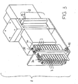
- Assembly unit 8 shown in perspective comprises 20 application units 2 and 20 photodiodes 3.
- Each of the photodiodes 3 is thus arranged such that it can detect the radiation of the additive of an adhesive bead which has been applied by one of the application units 2.
- each of the photodiodes 3 is assigned to an application unit 2.
- the photodiode 3a is assigned to the application unit 2a
- the photodiode 3b is assigned to the application unit 2b, etc.
- the structural unit 8 is designed and arranged in the device such that, in the event of a fault, it can be exchanged for another structural unit 8 'by the method according to the invention.
- FIG. 4 shows a wooden structure 10 in the form of a glued laminated timber, which comprises a plurality of components which are fixedly connected to each other by means of an adhesive connection 20,21.
- some of the adhesive compounds are designed as finger jointing 20 and others as consultancynverklebung 21.
- an adhesive compound 20, 21 contains an adhesive with a luminescent additive that absorbs electromagnetic radiation in a first wavelength range, preferably in the UV range, and in a second wavelength range, preferably between 200 nm and 800 nm, more preferably between 300 nm and 650 nm, most preferably between 410 nm and 480 nm emitted.
- the adhesive compounds 20,21 are irradiated with an authentication light 17, which emits an excitation radiation in the first wavelength range. If the adhesive compound contains an adhesive with the additive, this absorbs the excitation radiation and emits light in the second wavelength range. This emitted light is optionally detected by an authentication sensor 16.
Landscapes
- Chemical & Material Sciences (AREA)
- Organic Chemistry (AREA)
- Engineering & Computer Science (AREA)
- Life Sciences & Earth Sciences (AREA)
- Manufacturing & Machinery (AREA)
- Wood Science & Technology (AREA)
- Forests & Forestry (AREA)
- Adhesives Or Adhesive Processes (AREA)
- Investigating, Analyzing Materials By Fluorescence Or Luminescence (AREA)
- Joining Of Building Structures In Genera (AREA)
- Veneer Processing And Manufacture Of Plywood (AREA)
Claims (8)
- Procédé pour relier au moins deux composants (9), en particulier des composants en bois, et comprenant les étapes qui consistent à :a) au moyen d'une unité d'application (2), appliquer au moins un cordon (6) d'adhésif sur au moins l'un des composants (9),b) surveiller l'application du cordon (6) d'adhésif au moyen d'au moins une photodiode (3) qui est associée au cordon (6) d'adhésif appliqué et/ou à l'unité d'application (2) etc) relier les composants (9) en les mettant en contact, de préférence en repoussant les composants (9) l'un contre l'autre,caractérisé en ce que le procédé utilise un adhésif (5) qui contient un additif luminescent et en particulier fluorescent et en ce que la photodiode (3) détecte le rayonnement émis par l'additif luminescent et en particulier fluorescent,
un signal d'erreur étant délivré lorsque l'application est absente. - Procédé selon la revendication 1, caractérisé en ce que le cordon (6) d'adhésif est irradié par un rayonnement d'excitation, en particulier par de la lumière UV, et en particulier uniquement dans une zone de détection (4) de la photodiode (3).
- Procédé selon la revendication 2, caractérisé en ce que la zone de détection (4) de la photodiode (3) ne saisit essentiellement que un cordon (6) d'adhésif.
- Procédé selon l'une des revendications précédentes, caractérisé en ce qu'en cas de présence du signal d'erreur, un signal d'alarme est émis et/ou le procédé est interrompu automatiquement.
- Dispositif (1) pour appliquer un adhésif (5) sur un composant (9), de préférence un matériau à base de bois, en particulier pour exécuter un procédé selon l'une des revendications 1 à 4, le dispositif comprenant :- au moins une unité d'application (2) qui applique des cordons (6) d'adhésif sur un composant (9),- au moins une photodiode (3) qui surveille l'application du cordon (6) d'adhésif sur le composant (9) et- des moyens d'éclairage (7) qui irradient les cordons (6) d'adhésif et émettent un rayonnement dans la plage des UV,caractérisé en ce que une photodiode (3) est associée à au moins une unité d'application (2),
un signal d'erreur pouvant être délivré lorsque l'application est absente. - Dispositif (1) selon la revendication 5, caractérisé en ce que le dispositif (1) est un dispositif pour appliquer un adhésif (5) sur des pièces de jonction et pour relier les pièces de jonction, en particulier une installation d'assemblage par dents collées.
- Dispositif (1) selon l'une des revendications 5 et 6, caractérisé en ce que le dispositif (1) peut être commandé sur base du signal d'erreur, et en particulier en ce qu'au moins l'une des unités d'application (2) peut être désactivée automatiquement.
- Procédé de remplacement et/ou de transformation d'un dispositif existant d'application d'adhésif (5) sous la forme d'un cordon d'adhésif sur un composant (9), comprenant l'installation d'au moins une photodiode (3) et d'un moyen d'éclairage (7) qui émet un rayonnement dans la plage des UV.
Priority Applications (3)
| Application Number | Priority Date | Filing Date | Title |
|---|---|---|---|
| AT07107166T ATE502986T1 (de) | 2007-04-27 | 2007-04-27 | Verfahren zum verbinden von (holz-)bauteilen |
| DE502007006770T DE502007006770D1 (de) | 2007-04-27 | 2007-04-27 | Verfahren zum Verbinden von (Holz-)Bauteilen |
| EP07107166.6A EP1985676B2 (fr) | 2007-04-27 | 2007-04-27 | Procédé de liaison de composants (en bois) |
Applications Claiming Priority (1)
| Application Number | Priority Date | Filing Date | Title |
|---|---|---|---|
| EP07107166.6A EP1985676B2 (fr) | 2007-04-27 | 2007-04-27 | Procédé de liaison de composants (en bois) |
Publications (3)
| Publication Number | Publication Date |
|---|---|
| EP1985676A1 EP1985676A1 (fr) | 2008-10-29 |
| EP1985676B1 EP1985676B1 (fr) | 2011-03-23 |
| EP1985676B2 true EP1985676B2 (fr) | 2019-03-20 |
Family
ID=38475908
Family Applications (1)
| Application Number | Title | Priority Date | Filing Date |
|---|---|---|---|
| EP07107166.6A Active EP1985676B2 (fr) | 2007-04-27 | 2007-04-27 | Procédé de liaison de composants (en bois) |
Country Status (3)
| Country | Link |
|---|---|
| EP (1) | EP1985676B2 (fr) |
| AT (1) | ATE502986T1 (fr) |
| DE (1) | DE502007006770D1 (fr) |
Families Citing this family (6)
| Publication number | Priority date | Publication date | Assignee | Title |
|---|---|---|---|---|
| DE102008056344A1 (de) * | 2008-11-07 | 2010-05-12 | Wilhelm Karmann Gmbh | Verfahren zur Herstellung einer Klebenaht an einem Verdeckbezug eines Kraftfahrzeuges |
| GB201004458D0 (en) | 2010-03-17 | 2010-05-05 | Dynea Oy | Contactless application of an adhesive |
| DE102012222377A1 (de) * | 2012-12-06 | 2014-07-10 | Bayerische Motoren Werke Aktiengesellschaft | Verfahren zur optischen Überprüfung einer Klebestelle |
| DE102021102830A1 (de) | 2021-02-08 | 2022-08-11 | Ats Automation Tooling Systems Gmbh | Verfahren und Vorrichtung zur Überprüfung einer Klebstoffverbindung zwischen einer Hohlnadel oder Kanüle und einem Halteteil |
| DE102022124059A1 (de) * | 2022-09-20 | 2024-03-21 | Bayerische Motoren Werke Aktiengesellschaft | System und Verfahren zur optischen Bewertung eines Auftrags wenigstens einer pastösen Masse auf einem Bauteil sowie ein Fahrzeug |
| AT528558A1 (de) | 2024-07-19 | 2026-02-15 | Fill Gmbh | Brettlamellenfügevorrichtung zum Verbinden von einzelnen Brettlamellen zu einem Lamellenteppich, sowie ein Verfahren zum Herstellen eines Verbundbauteiles mit einzelnen Brettlamellen |
Citations (1)
| Publication number | Priority date | Publication date | Assignee | Title |
|---|---|---|---|---|
| US7178896B2 (en) † | 2003-01-29 | 2007-02-20 | Hewlett-Packard Development Company, L.P. | Article of manufacture including a two-part adhesive with a fluorescent dye and method of making |
Family Cites Families (6)
| Publication number | Priority date | Publication date | Assignee | Title |
|---|---|---|---|---|
| DE4305991C1 (de) | 1993-02-26 | 1994-06-01 | Grecon Greten Gmbh & Co Kg | Verfahren zur Überwachung des Leimauftrags bei der Herstellung einer verleimten Keilzinkenverbindung zweier Hölzer |
| US5666325A (en) * | 1995-07-31 | 1997-09-09 | Nordson Corporation | Method and apparatus for monitoring and controlling the dispensing of materials onto a substrate |
| DE59910987D1 (de) | 1999-02-06 | 2004-12-09 | M T E Marketing Technik Engine | Verfahren und Einrichtung zur Leimerkennung |
| FR2802460B1 (fr) * | 1999-12-21 | 2005-06-24 | Rene Bloch | Procede de fabrication d'un produit en bois lamelle-colle et produit ainsi obtenu |
| DE102004021573A1 (de) | 2004-05-03 | 2005-12-01 | Adam Opel Ag | Inline-Kleberüberwachungssystem und Verfahren zur Überwachung von Kleberraupen und zur Kantenerkennung |
| DE102004022232A1 (de) * | 2004-05-04 | 2005-12-01 | Infineon Technologies Ag | Viskoses Klebematerial zur Befestigung elektronischer Bauelemente |
-
2007
- 2007-04-27 EP EP07107166.6A patent/EP1985676B2/fr active Active
- 2007-04-27 DE DE502007006770T patent/DE502007006770D1/de active Active
- 2007-04-27 AT AT07107166T patent/ATE502986T1/de active
Patent Citations (1)
| Publication number | Priority date | Publication date | Assignee | Title |
|---|---|---|---|---|
| US7178896B2 (en) † | 2003-01-29 | 2007-02-20 | Hewlett-Packard Development Company, L.P. | Article of manufacture including a two-part adhesive with a fluorescent dye and method of making |
Also Published As
| Publication number | Publication date |
|---|---|
| ATE502986T1 (de) | 2011-04-15 |
| EP1985676A1 (fr) | 2008-10-29 |
| EP1985676B1 (fr) | 2011-03-23 |
| DE502007006770D1 (de) | 2011-05-05 |
Similar Documents
| Publication | Publication Date | Title |
|---|---|---|
| EP1985676B1 (fr) | Procédé de liaison de composants (en bois) | |
| DE102009039029B4 (de) | Verfahren zum Fügen von mindestens zwei Bauteilen unter Verwendung einer dualhärtenden Klebstoffzusammensetzung | |
| DE112007002751T5 (de) | UV-Bestrahlungsvorrichtung und UV-Bestrahlungsverfahren | |
| DE112010005248T5 (de) | Modulare led-array-lichtquellen von hoher dichte | |
| DE102015115894A1 (de) | Zeugnisfähige Befestigungseinrichtungen und verwandte Systeme und Verfahren | |
| EP3108177A1 (fr) | Dispositif d'éclairage équipé d'au moins une source de lumière primaire et d'un volume de substance fluorescente | |
| DE102020203506A1 (de) | Wellenlängenumwandlungselement, lichtquellenvorrichtung und beleuchtungsvorrichtung | |
| EP2846146A1 (fr) | essai de vieillissement avec plusieurs sources de rayonnement commandables indépendamment | |
| EP1502859B1 (fr) | Dispositif et procédé pour vérifier un objet collé | |
| DE4305991C1 (de) | Verfahren zur Überwachung des Leimauftrags bei der Herstellung einer verleimten Keilzinkenverbindung zweier Hölzer | |
| DE102016102901B4 (de) | Verfahren zum Verbinden von Komponenten unter Verwendung eines mit Energiestrahlen härtbaren Klebstoffs | |
| DE112015004032T5 (de) | Led-dentallichtquelle mit veränderlicher chromatizität und verfahren | |
| EP2473090B1 (fr) | Appareil d'éclairage médical pour lumière d'arrière-plan et lumière d'excitation | |
| EP3394503B1 (fr) | Phare pour véhicules doté d'au moins un module de lumière laser | |
| EP2929324A1 (fr) | Procédé de contrôle optique d'un collage | |
| WO2021004976A1 (fr) | Film adhésif (semi)structural compressible, activable par uv ou thermiquement, présentant un changement de couleur respectivement après activation et durcissement | |
| WO2007113287A1 (fr) | Utilisation de la thermographie infrarouge comme moyen pour déterminer l'évolution du durcissement d'une composition à deux composantes | |
| DE10251775A1 (de) | Verfahren zum Fügen von Plattenelementen einer Brennstoffzelleneinheit | |
| EP1025968B1 (fr) | Procédé et appareil pour la détection de colle | |
| EP1308477A1 (fr) | Matière plastique photodurcissable comportant un indicateur de degré de durcissement | |
| WO2020119898A1 (fr) | Film adhésif enroulable et emboutissable | |
| EP3788112B1 (fr) | Bande adhésive pouvant être enroulée et poinçonnée destinée à une activation par uv sélective | |
| EP2191324A1 (fr) | Élément de surface photoémetteur et procédé de fabrication d'un élément de surface photoémetteur | |
| DE102020122217B4 (de) | Beleuchtungsvorrichtung mit Lichtleitfasermodul und Verfahren zur Herstellung eines Lichtleitfasermoduls | |
| EP1234648A1 (fr) | Procédé et apparaeil de préactivation de matières polymérisables par voie cationique |
Legal Events
| Date | Code | Title | Description |
|---|---|---|---|
| PUAI | Public reference made under article 153(3) epc to a published international application that has entered the european phase |
Free format text: ORIGINAL CODE: 0009012 |
|
| AK | Designated contracting states |
Kind code of ref document: A1 Designated state(s): AT BE BG CH CY CZ DE DK EE ES FI FR GB GR HU IE IS IT LI LT LU LV MC MT NL PL PT RO SE SI SK TR |
|
| AX | Request for extension of the european patent |
Extension state: AL BA HR MK RS |
|
| RAP1 | Party data changed (applicant data changed or rights of an application transferred) |
Owner name: PURBOND AG |
|
| 17P | Request for examination filed |
Effective date: 20090314 |
|
| 17Q | First examination report despatched |
Effective date: 20090504 |
|
| AKX | Designation fees paid |
Designated state(s): AT BE BG CH CY CZ DE DK EE ES FI FR GB GR HU IE IS IT LI LT LU LV MC MT NL PL PT RO SE SI SK TR |
|
| GRAP | Despatch of communication of intention to grant a patent |
Free format text: ORIGINAL CODE: EPIDOSNIGR1 |
|
| GRAS | Grant fee paid |
Free format text: ORIGINAL CODE: EPIDOSNIGR3 |
|
| GRAA | (expected) grant |
Free format text: ORIGINAL CODE: 0009210 |
|
| AK | Designated contracting states |
Kind code of ref document: B1 Designated state(s): AT BE BG CH CY CZ DE DK EE ES FI FR GB GR HU IE IS IT LI LT LU LV MC MT NL PL PT RO SE SI SK TR |
|
| REG | Reference to a national code |
Ref country code: GB Ref legal event code: FG4D Free format text: NOT ENGLISH |
|
| REG | Reference to a national code |
Ref country code: CH Ref legal event code: EP |
|
| REG | Reference to a national code |
Ref country code: IE Ref legal event code: FG4D |
|
| REG | Reference to a national code |
Ref country code: CH Ref legal event code: NV Representative=s name: HEPP WENGER RYFFEL AG |
|
| REF | Corresponds to: |
Ref document number: 502007006770 Country of ref document: DE Date of ref document: 20110505 Kind code of ref document: P |
|
| REG | Reference to a national code |
Ref country code: DE Ref legal event code: R096 Ref document number: 502007006770 Country of ref document: DE Effective date: 20110505 |
|
| REG | Reference to a national code |
Ref country code: NL Ref legal event code: VDEP Effective date: 20110323 |
|
| PG25 | Lapsed in a contracting state [announced via postgrant information from national office to epo] |
Ref country code: SE Free format text: LAPSE BECAUSE OF FAILURE TO SUBMIT A TRANSLATION OF THE DESCRIPTION OR TO PAY THE FEE WITHIN THE PRESCRIBED TIME-LIMIT Effective date: 20110323 Ref country code: LV Free format text: LAPSE BECAUSE OF FAILURE TO SUBMIT A TRANSLATION OF THE DESCRIPTION OR TO PAY THE FEE WITHIN THE PRESCRIBED TIME-LIMIT Effective date: 20110323 Ref country code: LT Free format text: LAPSE BECAUSE OF FAILURE TO SUBMIT A TRANSLATION OF THE DESCRIPTION OR TO PAY THE FEE WITHIN THE PRESCRIBED TIME-LIMIT Effective date: 20110323 Ref country code: GR Free format text: LAPSE BECAUSE OF FAILURE TO SUBMIT A TRANSLATION OF THE DESCRIPTION OR TO PAY THE FEE WITHIN THE PRESCRIBED TIME-LIMIT Effective date: 20110624 |
|
| LTIE | Lt: invalidation of european patent or patent extension |
Effective date: 20110323 |
|
| PG25 | Lapsed in a contracting state [announced via postgrant information from national office to epo] |
Ref country code: SI Free format text: LAPSE BECAUSE OF FAILURE TO SUBMIT A TRANSLATION OF THE DESCRIPTION OR TO PAY THE FEE WITHIN THE PRESCRIBED TIME-LIMIT Effective date: 20110323 Ref country code: BG Free format text: LAPSE BECAUSE OF FAILURE TO SUBMIT A TRANSLATION OF THE DESCRIPTION OR TO PAY THE FEE WITHIN THE PRESCRIBED TIME-LIMIT Effective date: 20110623 Ref country code: CY Free format text: LAPSE BECAUSE OF FAILURE TO SUBMIT A TRANSLATION OF THE DESCRIPTION OR TO PAY THE FEE WITHIN THE PRESCRIBED TIME-LIMIT Effective date: 20110323 |
|
| REG | Reference to a national code |
Ref country code: IE Ref legal event code: FD4D |
|
| BERE | Be: lapsed |
Owner name: PURBOND A.G. Effective date: 20110430 |
|
| PG25 | Lapsed in a contracting state [announced via postgrant information from national office to epo] |
Ref country code: EE Free format text: LAPSE BECAUSE OF FAILURE TO SUBMIT A TRANSLATION OF THE DESCRIPTION OR TO PAY THE FEE WITHIN THE PRESCRIBED TIME-LIMIT Effective date: 20110323 Ref country code: PT Free format text: LAPSE BECAUSE OF FAILURE TO SUBMIT A TRANSLATION OF THE DESCRIPTION OR TO PAY THE FEE WITHIN THE PRESCRIBED TIME-LIMIT Effective date: 20110725 |
|
| PG25 | Lapsed in a contracting state [announced via postgrant information from national office to epo] |
Ref country code: CZ Free format text: LAPSE BECAUSE OF FAILURE TO SUBMIT A TRANSLATION OF THE DESCRIPTION OR TO PAY THE FEE WITHIN THE PRESCRIBED TIME-LIMIT Effective date: 20110323 Ref country code: MC Free format text: LAPSE BECAUSE OF NON-PAYMENT OF DUE FEES Effective date: 20110430 Ref country code: SK Free format text: LAPSE BECAUSE OF FAILURE TO SUBMIT A TRANSLATION OF THE DESCRIPTION OR TO PAY THE FEE WITHIN THE PRESCRIBED TIME-LIMIT Effective date: 20110323 Ref country code: ES Free format text: LAPSE BECAUSE OF FAILURE TO SUBMIT A TRANSLATION OF THE DESCRIPTION OR TO PAY THE FEE WITHIN THE PRESCRIBED TIME-LIMIT Effective date: 20110704 Ref country code: IS Free format text: LAPSE BECAUSE OF FAILURE TO SUBMIT A TRANSLATION OF THE DESCRIPTION OR TO PAY THE FEE WITHIN THE PRESCRIBED TIME-LIMIT Effective date: 20110723 Ref country code: RO Free format text: LAPSE BECAUSE OF FAILURE TO SUBMIT A TRANSLATION OF THE DESCRIPTION OR TO PAY THE FEE WITHIN THE PRESCRIBED TIME-LIMIT Effective date: 20110323 |
|
| PLBI | Opposition filed |
Free format text: ORIGINAL CODE: 0009260 |
|
| PLBI | Opposition filed |
Free format text: ORIGINAL CODE: 0009260 |
|
| PG25 | Lapsed in a contracting state [announced via postgrant information from national office to epo] |
Ref country code: NL Free format text: LAPSE BECAUSE OF FAILURE TO SUBMIT A TRANSLATION OF THE DESCRIPTION OR TO PAY THE FEE WITHIN THE PRESCRIBED TIME-LIMIT Effective date: 20110323 Ref country code: MT Free format text: LAPSE BECAUSE OF FAILURE TO SUBMIT A TRANSLATION OF THE DESCRIPTION OR TO PAY THE FEE WITHIN THE PRESCRIBED TIME-LIMIT Effective date: 20110323 |
|
| 26 | Opposition filed |
Opponent name: AKZO NOBEL CHEMICALS INTERNATIONAL B.V. Effective date: 20111205 |
|
| 26 | Opposition filed |
Opponent name: AKZO NOBEL CHEMICALS INTERNATIONAL B.V. Effective date: 20111205 Opponent name: JOWAT AG Effective date: 20111220 |
|
| PLAX | Notice of opposition and request to file observation + time limit sent |
Free format text: ORIGINAL CODE: EPIDOSNOBS2 |
|
| PG25 | Lapsed in a contracting state [announced via postgrant information from national office to epo] |
Ref country code: BE Free format text: LAPSE BECAUSE OF NON-PAYMENT OF DUE FEES Effective date: 20110430 Ref country code: IE Free format text: LAPSE BECAUSE OF FAILURE TO SUBMIT A TRANSLATION OF THE DESCRIPTION OR TO PAY THE FEE WITHIN THE PRESCRIBED TIME-LIMIT Effective date: 20110323 |
|
| GBPC | Gb: european patent ceased through non-payment of renewal fee |
Effective date: 20110623 |
|
| PG25 | Lapsed in a contracting state [announced via postgrant information from national office to epo] |
Ref country code: PL Free format text: LAPSE BECAUSE OF FAILURE TO SUBMIT A TRANSLATION OF THE DESCRIPTION OR TO PAY THE FEE WITHIN THE PRESCRIBED TIME-LIMIT Effective date: 20110323 |
|
| REG | Reference to a national code |
Ref country code: DE Ref legal event code: R026 Ref document number: 502007006770 Country of ref document: DE Effective date: 20111205 |
|
| PLAB | Opposition data, opponent's data or that of the opponent's representative modified |
Free format text: ORIGINAL CODE: 0009299OPPO |
|
| PLAF | Information modified related to communication of a notice of opposition and request to file observations + time limit |
Free format text: ORIGINAL CODE: EPIDOSCOBS2 |
|
| PG25 | Lapsed in a contracting state [announced via postgrant information from national office to epo] |
Ref country code: IT Free format text: LAPSE BECAUSE OF FAILURE TO SUBMIT A TRANSLATION OF THE DESCRIPTION OR TO PAY THE FEE WITHIN THE PRESCRIBED TIME-LIMIT Effective date: 20110323 |
|
| R26 | Opposition filed (corrected) |
Opponent name: JOWAT AG Effective date: 20111220 Opponent name: AKZO NOBEL CHEMICALS INTERNATIONAL B.V. Effective date: 20111205 |
|
| PG25 | Lapsed in a contracting state [announced via postgrant information from national office to epo] |
Ref country code: GB Free format text: LAPSE BECAUSE OF NON-PAYMENT OF DUE FEES Effective date: 20110623 |
|
| PLBB | Reply of patent proprietor to notice(s) of opposition received |
Free format text: ORIGINAL CODE: EPIDOSNOBS3 |
|
| PG25 | Lapsed in a contracting state [announced via postgrant information from national office to epo] |
Ref country code: LU Free format text: LAPSE BECAUSE OF NON-PAYMENT OF DUE FEES Effective date: 20110427 |
|
| PG25 | Lapsed in a contracting state [announced via postgrant information from national office to epo] |
Ref country code: TR Free format text: LAPSE BECAUSE OF FAILURE TO SUBMIT A TRANSLATION OF THE DESCRIPTION OR TO PAY THE FEE WITHIN THE PRESCRIBED TIME-LIMIT Effective date: 20110323 |
|
| PG25 | Lapsed in a contracting state [announced via postgrant information from national office to epo] |
Ref country code: HU Free format text: LAPSE BECAUSE OF FAILURE TO SUBMIT A TRANSLATION OF THE DESCRIPTION OR TO PAY THE FEE WITHIN THE PRESCRIBED TIME-LIMIT Effective date: 20110323 |
|
| PLAY | Examination report in opposition despatched + time limit |
Free format text: ORIGINAL CODE: EPIDOSNORE2 |
|
| PLBC | Reply to examination report in opposition received |
Free format text: ORIGINAL CODE: EPIDOSNORE3 |
|
| APBM | Appeal reference recorded |
Free format text: ORIGINAL CODE: EPIDOSNREFNO |
|
| APBP | Date of receipt of notice of appeal recorded |
Free format text: ORIGINAL CODE: EPIDOSNNOA2O |
|
| APBM | Appeal reference recorded |
Free format text: ORIGINAL CODE: EPIDOSNREFNO |
|
| APBP | Date of receipt of notice of appeal recorded |
Free format text: ORIGINAL CODE: EPIDOSNNOA2O |
|
| APBM | Appeal reference recorded |
Free format text: ORIGINAL CODE: EPIDOSNREFNO |
|
| APBP | Date of receipt of notice of appeal recorded |
Free format text: ORIGINAL CODE: EPIDOSNNOA2O |
|
| APAH | Appeal reference modified |
Free format text: ORIGINAL CODE: EPIDOSCREFNO |
|
| APBQ | Date of receipt of statement of grounds of appeal recorded |
Free format text: ORIGINAL CODE: EPIDOSNNOA3O |
|
| APBQ | Date of receipt of statement of grounds of appeal recorded |
Free format text: ORIGINAL CODE: EPIDOSNNOA3O |
|
| PLAB | Opposition data, opponent's data or that of the opponent's representative modified |
Free format text: ORIGINAL CODE: 0009299OPPO |
|
| R26 | Opposition filed (corrected) |
Opponent name: AKZO NOBEL COATINGS INTERNATIONAL B.V. Effective date: 20111205 |
|
| APAH | Appeal reference modified |
Free format text: ORIGINAL CODE: EPIDOSCREFNO |
|
| APAW | Appeal reference deleted |
Free format text: ORIGINAL CODE: EPIDOSDREFNO |
|
| REG | Reference to a national code |
Ref country code: FR Ref legal event code: PLFP Year of fee payment: 10 |
|
| REG | Reference to a national code |
Ref country code: FR Ref legal event code: PLFP Year of fee payment: 11 |
|
| PLAB | Opposition data, opponent's data or that of the opponent's representative modified |
Free format text: ORIGINAL CODE: 0009299OPPO |
|
| R26 | Opposition filed (corrected) |
Opponent name: AKZO NOBEL COATINGS INTERNATIONAL B.V. Effective date: 20111205 |
|
| REG | Reference to a national code |
Ref country code: FR Ref legal event code: PLFP Year of fee payment: 12 |
|
| RAP2 | Party data changed (patent owner data changed or rights of a patent transferred) |
Owner name: HENKEL SWITZERLAND OPERATIONS AG |
|
| REG | Reference to a national code |
Ref country code: CH Ref legal event code: PFA Owner name: HENKEL SWITZERLAND OPERATIONS AG, CH Free format text: FORMER OWNER: PURBOND AG, CH |
|
| APBU | Appeal procedure closed |
Free format text: ORIGINAL CODE: EPIDOSNNOA9O |
|
| PUAH | Patent maintained in amended form |
Free format text: ORIGINAL CODE: 0009272 |
|
| STAA | Information on the status of an ep patent application or granted ep patent |
Free format text: STATUS: PATENT MAINTAINED AS AMENDED |
|
| REG | Reference to a national code |
Ref country code: CH Ref legal event code: AELC |
|
| 27A | Patent maintained in amended form |
Effective date: 20190320 |
|
| AK | Designated contracting states |
Kind code of ref document: B2 Designated state(s): AT BE BG CH CY CZ DE DK EE ES FI FR GB GR HU IE IS IT LI LT LU LV MC MT NL PL PT RO SE SI SK TR |
|
| REG | Reference to a national code |
Ref country code: DE Ref legal event code: R102 Ref document number: 502007006770 Country of ref document: DE |
|
| P01 | Opt-out of the competence of the unified patent court (upc) registered |
Effective date: 20230629 |
|
| PGFP | Annual fee paid to national office [announced via postgrant information from national office to epo] |
Ref country code: FI Payment date: 20250424 Year of fee payment: 19 |
|
| PGFP | Annual fee paid to national office [announced via postgrant information from national office to epo] |
Ref country code: DE Payment date: 20250422 Year of fee payment: 19 |
|
| PGFP | Annual fee paid to national office [announced via postgrant information from national office to epo] |
Ref country code: FR Payment date: 20250424 Year of fee payment: 19 |
|
| PGFP | Annual fee paid to national office [announced via postgrant information from national office to epo] |
Ref country code: CH Payment date: 20250501 Year of fee payment: 19 |
|
| PGFP | Annual fee paid to national office [announced via postgrant information from national office to epo] |
Ref country code: AT Payment date: 20250423 Year of fee payment: 19 |