EP2155498B1 - Dispositif et procédé pour transférer magnétiquement un indice vers une composition de revêtement appliquée à un substrat - Google Patents
Dispositif et procédé pour transférer magnétiquement un indice vers une composition de revêtement appliquée à un substrat Download PDFInfo
- Publication number
- EP2155498B1 EP2155498B1 EP08738092.9A EP08738092A EP2155498B1 EP 2155498 B1 EP2155498 B1 EP 2155498B1 EP 08738092 A EP08738092 A EP 08738092A EP 2155498 B1 EP2155498 B1 EP 2155498B1
- Authority
- EP
- European Patent Office
- Prior art keywords
- layer
- magnetic
- coating composition
- magnetic field
- magnetic permeability
- Prior art date
- Legal status (The legal status is an assumption and is not a legal conclusion. Google has not performed a legal analysis and makes no representation as to the accuracy of the status listed.)
- Active
Links
Images


Classifications
-
- B—PERFORMING OPERATIONS; TRANSPORTING
- B41—PRINTING; LINING MACHINES; TYPEWRITERS; STAMPS
- B41M—PRINTING, DUPLICATING, MARKING, OR COPYING PROCESSES; COLOUR PRINTING
- B41M7/00—After-treatment of prints, e.g. heating, irradiating, setting of the ink, protection of the printed stock
- B41M7/0045—After-treatment of prints, e.g. heating, irradiating, setting of the ink, protection of the printed stock using protective coatings or film forming compositions cured by mechanical wave energy, e.g. ultrasonics, cured by electromagnetic radiation or waves, e.g. ultraviolet radiation, electron beams, or cured by magnetic or electric fields, e.g. electric discharge, plasma
-
- B—PERFORMING OPERATIONS; TRANSPORTING
- B41—PRINTING; LINING MACHINES; TYPEWRITERS; STAMPS
- B41M—PRINTING, DUPLICATING, MARKING, OR COPYING PROCESSES; COLOUR PRINTING
- B41M3/00—Printing processes to produce particular kinds of printed work, e.g. patterns
- B41M3/14—Security printing
-
- B—PERFORMING OPERATIONS; TRANSPORTING
- B41—PRINTING; LINING MACHINES; TYPEWRITERS; STAMPS
- B41M—PRINTING, DUPLICATING, MARKING, OR COPYING PROCESSES; COLOUR PRINTING
- B41M7/00—After-treatment of prints, e.g. heating, irradiating, setting of the ink, protection of the printed stock
- B41M7/0036—After-treatment of prints, e.g. heating, irradiating, setting of the ink, protection of the printed stock using protective coatings or layers dried without curing
-
- B—PERFORMING OPERATIONS; TRANSPORTING
- B42—BOOKBINDING; ALBUMS; FILES; SPECIAL PRINTED MATTER
- B42D—BOOKS; BOOK COVERS; LOOSE LEAVES; PRINTED MATTER CHARACTERISED BY IDENTIFICATION OR SECURITY FEATURES; PRINTED MATTER OF SPECIAL FORMAT OR STYLE NOT OTHERWISE PROVIDED FOR; DEVICES FOR USE THEREWITH AND NOT OTHERWISE PROVIDED FOR; MOVABLE-STRIP WRITING OR READING APPARATUS
- B42D25/00—Information-bearing cards or sheet-like structures characterised by identification or security features; Manufacture thereof
- B42D25/20—Information-bearing cards or sheet-like structures characterised by identification or security features; Manufacture thereof characterised by a particular use or purpose
- B42D25/29—Securities; Bank notes
-
- B—PERFORMING OPERATIONS; TRANSPORTING
- B42—BOOKBINDING; ALBUMS; FILES; SPECIAL PRINTED MATTER
- B42D—BOOKS; BOOK COVERS; LOOSE LEAVES; PRINTED MATTER CHARACTERISED BY IDENTIFICATION OR SECURITY FEATURES; PRINTED MATTER OF SPECIAL FORMAT OR STYLE NOT OTHERWISE PROVIDED FOR; DEVICES FOR USE THEREWITH AND NOT OTHERWISE PROVIDED FOR; MOVABLE-STRIP WRITING OR READING APPARATUS
- B42D25/00—Information-bearing cards or sheet-like structures characterised by identification or security features; Manufacture thereof
- B42D25/30—Identification or security features, e.g. for preventing forgery
- B42D25/36—Identification or security features, e.g. for preventing forgery comprising special materials
- B42D25/369—Magnetised or magnetisable materials
-
- B42D2033/16—
Definitions
- the present invention generally relates to a device and method for magnetically transferring indicia to a coating composition, such as an ink or varnish, applied to at least a part of the surface of a substrate, which coating composition comprises magnetic or magnetizable particles.
- a coating composition such as an ink or varnish
- the present invention also relates to the use of such a device and the application of such a method to produce printed documents, such as banknotes or like valuable and security documents.
- a layer of coating composition such as an ink or varnish, is first applied to at least a part of the surface of a substrate, which coating composition comprises at least one type of magnetic or magnetizable particles. While the layer of coating composition is still wet, the layer is exposed to a determined magnetic field generated at a surface of a magnetic-field-generating device, thereby orienting the magnetic or magnetizable particles along field lines of the magnetic field. The layer of coating composition is then dried or cured, thereby fixing the orientation of the magnetic or magnetizable particles.
- European patent application No. EP 1 787 728 discloses a magnetic plate for printing of optical effects, which plate comprises a magnetizable composite material that is selectively magnetized so that one or more first regions across the surface of the plate provide a first magnetic field having a predetermined direction. These first regions form a logo, indicia or image of an object. Magnetic material in one or more other second regions surrounding the first region are either unmagnetized or magnetized differently from the one or more first regions so as to provide a contrast in magnetic field.
- Magnetic or magnetizable particles also designated as “magnetic flakes"
- magnetic flakes Magnetic or magnetizable particles
- European patent application EP 0 686 675 European patent application EP 0 686 675
- International applications WO 02/073250 WO 03/000801 , WO 2004/007095 , WO 2004/007096 and WO 2005/002866 .
- Such particles or flakes are in particular used as optically-variable pigments in so-called optically-variable inks, or OVI®'s (OVI® is a registered trademark of SICPA Holding SA, Switzerland) to produce high-level security patterns, especially for banknotes.
- the most convenient method to apply the above magnetic flakes is by silk-screen printing as discussed in the above-mentioned International application WO 2005/000585 .
- This is mainly due to the fact that the flakes have a relatively important size which restricts the choice of available printing processes for applying inks or varnishes containing such flakes.
- silk-screen printing constitutes the most convenient printing process to achieve this goal.
- silk-screen printing has the advantage that the inks or varnishes used in such a process exhibit a relatively low viscosity which favours proper orientation of the magnetic flakes.
- Orientation of the magnetic flakes contained in the wet coating composition is carried out by applying an adequate magnetic field to the freshly-applied layer of coating composition.
- an adequate magnetic field By appropriately shaping the field lines of the magnetic field, the magnetic flakes can be aligned in any desired pattern producing a corresponding optically-variable effect which is very difficult, if not impossible to counterfeit.
- An adequate solution for orienting the magnetic flakes as discussed in International application WO 2005/000585 consists in bringing sheets carrying layers of wet coating composition in contact with a rotating cylinder carrying a plurality of magnetic-field-generating devices.
- Figure 1 is a schematic cross-sectional view of a magnetic field simulation taken from the above-mentioned International application which illustrates an example of a vertically magnetized permanent magnetic plate, designated by numerical reference 1, comprising a rectangular engraving 2.
- the engraved plate 1 is made of Plastoferrite (such as the Plastoferrite model M100.8 sold by Maurer Magnetic AG, CH-8627 Grüningen, http://www.maurermagnetic.ch ) magnetized in a direction perpendicular to the surface of the plate 1.
- Plastoferrite such as the Plastoferrite model M100.8 sold by Maurer Magnetic AG, CH-8627 Grüningen, http://www.maurermagnetic.ch
- the field lines of the magnetic field are mostly vertical in the region of the surface of the body, except in the region of the vertical walls of the engraving 2. This implies that most of the magnetic pigments contained in the wet composition are aligned in a vertical manner, perpendicularly to the surface of the substrate. In other words, considering the fact that the pigments are mostly reflective when they are aligned substantially horizontally, the resulting pattern induced in the coating composition by means of the device of Figure 1 is mostly not reflective, when seen and illuminated perpendicularly to the surface of the substrate.
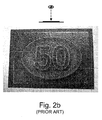
- Figures 2a to 2c are greyscale photographs, taken along three different viewing angles, of a magnetically-induced pattern representing the value "50" within an oval shape which was produced by means of a device according to the principle of International application WO 2005/002866 illustrated in Figure 1 . More precisely, the pattern was produced using a body having engravings representing the value "50" within an engraved oval shape.
- the layer of coating composition was applied with a silk-screen printing process on top of a black offset background using an OVI® silk-screen ink comprising gold-to-green optically variable magnetic pigment corresponding to the 7-layer pigment design disclosed in WO 02/73250 .
- the purpose of the black (or dark) offset background is to increase the contrast in the induced pattern by making the reflective parts of the pattern (i.e. the portions where the pigments are oriented substantially horizontally with respect to the surface of the substrate) stand out as compared to the less reflective parts of the pattern (i.e. the portions where the pigments are oriented substantially vertically with respect to the surface of the substrate, thereby revealing the underlying background).
- WO 2006/114289 discloses a method for creating color effect images on a carrier substrate.
- a latent magnetic image comprising magnetic pixels and non-magnetic pixels is created on a magnetizable printing form.
- a carrier substrate provided with a decorative layer containing non-spherical, preferably needle shaped or lamellar magnetic color effect pigments is guided past the magnetizable printing form such that the orientation of color effect pigments of the decorative layer relative to the carrier substrate changes with the aid of the images of the field lines created by the magnetic pixels of the magnetizable printing form.
- the color pigments are ultimately fixed in the decorative layer with the orientation thereof modified by the magnetizable printing form.
- the magnetizable printing form comprises a soft magnetic band and electromagnetic printing heads are used to locally change the magnetic coercivity of the soft magnetic band to form the desired magnetic pixels.
- a "soft magnetic” material is commonly understood as designating a magnetizable material which has the ability to lose its memory of previous magnetizations, as opposed to “hard” or “permanent” magnetic material which stay magnetized for a long time.
- each magnetic pixels thus acts as an elementary magnet locally affecting the orientation of the field lines of the magnetic field.
- An aim of the invention is therefore to improve the known devices and methods for magnetically transferring indicia to a coating composition comprising magnetic or magnetizable particles
- a further aim of the present invention is to provide a device for magnetically transferring indicia to a coating composition comprising magnetic or magnetizable particles that is relatively easy and cheap to produce.
- Still another aim of the present invention is to provide a solution that increases the level of security of the resulting magnetically-induced pattern and makes it even more difficult to counterfeit.
- Yet another aim of the present invention is to provide a solution that is robust and is suited for use in a conventional production environment such as that of a printing plant and/or for implementation thereof on a printing press.
- a device for magnetically transferring indicia to a layer of coating composition such as an ink or varnish, applied to at least a part of the surface of a substrate, the coating composition comprising at least one type of magnetic or magnetizable particles.
- the device comprises a body subjected to a magnetic field, which body carries determined indicia in the form of engravings on a surface of the body, which engravings influence the orientation of field lines of the magnetic field.
- the body further comprises at least one layer of material of high magnetic permeability in which the engravings are formed.
- the field lines of the magnetic field extend substantially parallel to the surface of the body inside the layer of material of high magnetic permeability.
- the field lines of the magnetic field are forced along different routes and orientations outside the layer of material of high magnetic permeability, the field lines of the magnetic field extending, in the regions directly above the engravings, substantially horizontally above the surface of the body where the layer of coating composition applied to the substrate is to be located.
- the body further comprises a base plate of material of low magnetic permeability supporting the layer of material of high magnetic permeability.
- the material of low magnetic permeability is understood as being a material having a magnetic permeability substantially equal to the magnetic permeability of vacuum ⁇ 0 and which does not substantially affect the field lines of the magnetic field and behaves substantially like free space or vacuum.
- the layer of material of high magnetic permeability can advantageously be deposited on the base plate by galvanization.
- the magnetic permeability of the base plate is preferably in the range of 1.25 to 1.26 ⁇ N/A 2 .
- a preferred material for the base plate is a non-ferromagnetic material such as copper, aluminium or alloys thereof.
- the effect can be maximized when the engravings in the layer of material of high magnetic permeability extend through the whole thickness of the layer.
- the magnetic permeability of the layer of material of high magnetic permeability is selected to be greater than 100 ⁇ N/A 2 (@ 0.002 T), preferably between 100 to 1000 ⁇ N/A 2 (@ 0.002 T).
- a suitable material is a ferromagnetic material such as iron, nickel, cobalt or alloys thereof.
- the thickness of the layer of material of high magnetic permeability is preferably selected so as to be greater or equal to 50 ⁇ m, even more preferably between 50 to 500 ⁇ m.
- the magnetic field can advantageously be generated by means of at least one permanent magnet or electromagnet, preferably two.
- the field lines of the magnetic field can extend along substantially one main direction.
- the device of the present invention can advantageously be shaped as a curved plate adapted for mounting onto a rotatable cylinder body of a printing press or as an individual curved plate element adapted for mounting onto a supporting member disposed on the circumference of a cylindrical body of a printing press.
- Also claimed is a method for magnetically transferring indicia onto a substrate, comprising the steps of :
- the coating composition is preferably applied by printing, even more preferably by silk-screen printing, flexographic printing or gravure printing.
- Yet another claimed object is the use of the above device for magnetically inducing transfer of indicia to a wet coating composition, such an ink or varnish, applied to at least a part of the surface of a substrate, which coating composition comprises at least one type of magnetic or magnetizable particles.
- magnetically transferring indicia (which expression is also used in International application WO 2005/002866 ) is used in the context of the present invention because indicia is virtually “transferred” from an indicia-bearing body to the wet coating composition comprising the magnetic or magnetizable particles thanks to a determined orientation of the field lines of a magnetic field as this will be explained.
- transferring is to be understood as being equivalent to the term “forming” or “inducing” (which terms can therefore also be used to designate the indicia creation process).
- Figure 3 is a schematic cross-sectional view of a magnetic-field-generating device, designated globally by reference numeral 10, according to a preferred embodiment of the present invention.
- the device 10 includes a body 20 the purpose of which is to influence the orientation of field lines of a magnetic field, as this will be explained hereinafter.
- the body 20 comprises a layer 21 made of material of high magnetic permeability in which engravings 21 a, 21 b, 21 c are formed, and a base plate 22 made of material of low magnetic permeability which supports the layer 21.
- FIG. 3 Also illustrated in Figure 3 is a sheet S disposed on top of the surface of the body 20 in contact with the upper surface of layer 21, which sheet S comprises a layer of coating composition P applied on the surface of the sheet S, opposite the surface of layer 21.
- Coating composition P comprises at least one type of magnetic or magnetizable particles, as discussed hereinabove, that one wishes to orient by means of the magnetic-field-generating device 10.
- the method for magnetically transferring indicia onto the substrate S comprises the steps of :
- a material of "high magnetic permeability” is a material that has the ability to concentrate the field lines of a magnetic field (i.e. is “magnetically attractable")
- a material of "low magnetic permeability” is a material that does not substantially affect the field lines of a magnetic field and behaves substantially like free space or vacuum.
- the material of low magnetic permeability is selected to be a material having a magnetic permeability in the range of 1.25 to 1.26 ⁇ N/A 2 .
- a material of "high magnetic permeability” is a material having a magnetic permeability ⁇ that is substantially greater than ⁇ 0 . More precisely, according to the present invention, material of high magnetic permeability will be understood as materials preferably exhibiting a magnetic permeability greater than 100 ⁇ N/A 2 (@ 0.002 T), even more preferably materials exhibiting a magnetic permeability between 100 to 1000 ⁇ N/A 2 (@ 0.002 T). It shall be understood that the magnetic permeability of materials varies with flux density. The above-mentioned values are therefore given considering a flux density of 0.002 T (hence the indication "@ 0.002 T" following the mentioned values).
- ferromagnetic materials such as iron, nickel, cobalt or alloys thereof (e.g. steel, permalloy, etc.).
- any material of high magnetic permeability is suitable. Tests have however shown that material exhibiting a magnetic permeability comprised between 100 to 1000 ⁇ N/A 2 (@ 0.002 T) are sufficient, and that materials exhibiting a magnetic permeability higher than 1000 ⁇ N/A 2 (@ 0.002 T), while also suitable, are not necessary.
- a particularly suitable material for layer 21 is nickel, which material has a magnetic permeability of approximately 125 ⁇ N/A 2 (@ 0.002 T).
- This material is convenient as it is commonly used in the banknote industry to produce intaglio printing plates, especially by galvanization, and is thus readily available to the banknote printer.
- This material is furthermore very easy to engrave (for instance mechanically by means of a rotating chisel or by means of gaseous or liquid jets of abrasives, by chemical etching, or even by laser ablation using CO 2 , Nd-YAG or excimer lasers).
- non-ferromagnetic materials such as copper, aluminium or alloys thereof.
- any material of low magnetic permeability is suitable. Glass or plastic could for instance be used as material for the base plate 22.
- the base plate 22 of material of low magnetic permeability is therefore not essential but preferred.
- a particularly suitable material for base plate 22 is copper, which material has a magnetic permeability of approximately 1.2566290 ⁇ N/A 2 . This material is also convenient as it is again commonly used in the banknote industry and is thus readily available to the banknote printer.
- a perfectly suitable alternative is aluminium which exhibits a magnetic permeability of approximately 1.2566650 ⁇ N/A 2 .
- the copper base plate 22 was approximately 0.5 mm thick and the nickel layer 21 was deposited by galvanization with layer thicknesses ranging from 50 to 500 ⁇ m.
- the magnetic field is generated in this example by a pair of permanent magnets 31, 32 (such as samarium-cobalt - SmCo - magnets as supplied by Maurer Magnetic AG) disposed at two ends I, II of the device 10.
- the permanent magnet 31 is disposed with its north magnetic pole oriented upwards
- the permanent magnet 32 is disposed with its north magnetic pole oriented downwards.
- the resulting magnetic field is such that field lines of the magnetic field will extend from the north magnetic pole of permanent magnet 31 at end I through the base plate 22, into layer 21, then substantially horizontally through, above and below the layer 21, from end I to end II, back through the base plate 22 and to the south magnetic pole of permanent magnet 32.
- the remainder of the magnetic circuit is closed through connection of the magnetic field lines at the lower part of the device, via the north magnetic pole of permanent magnet 32 and the south magnetic pole of permanent magnet 31. It will be appreciated that the same magnetic field configuration could alternatively be generated using electromagnets instead of the permanent magnets 31, 32.
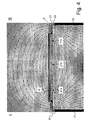
- FIG. 4 A simulation of the resulting magnetic field distribution is shown schematically in Figure 4 .
- This simulation was produced using the publicly available modelling software Vizimag ( http://www.vonmag.com/ ) and considering a nickel layer as layer 21 and a copper base plate as base plate 22.
- the magnetic field lines would mostly be concentrated in the layer 21 itself, this layer 21 acting as a magnetic short-circuit.
- the engravings 21 a, 21 b, 21 c in the layer 21, which form in essence regions of low magnetic permeability (i.e. free space), force the magnetic field lines along different routes and orientations. In other words, the engravings 21 a, 21 b, 21 c influence the orientation of the field lines of the magnetic field in the vicinity of the engravings 21a, 21b, 21c.
- Figures 5a to 5d are greyscale photographs taken from four different viewing angles of a magnetically induced pattern representing the value "50" within an oval shape, similar to the prior pattern illustrated in Figures 2a to 2c , but which was produced by means of a device according to the above-discussed preferred embodiment of the present invention.
- the body of the magnetic-field-generating device was engraved with exactly the same engraving pattern representing value "50" within an oval shape as that used for producing the prior pattern of Figures 2a to 2c .
- the above mentioned copper-nickel (Cu-Ni) body 20 was used.
- the engravings in the layer of material of high magnetic permeability are basically formed of an oval-shaped engraving inside which there remains an unengraved pattern representing the value "50".
- the resulting pattern is substantially more reflective and exhibits a radically different optical effect as compared to that illustrated in Figures 2a to 2c .
- the optical effect created according to the invention is more or less inverted as compared to the optical effect illustrated in Figures 2a to 2c .
- the oval shape appears to stand out in relief above the background, like a solid volume, with the value "50" looking like having been engraved into the solid oval shape.
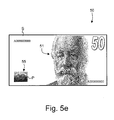
- Figure 5e is a schematic illustration of a possible banknote 50 comprising inter alia a portrait 51 and a magnetically-induced pattern 55 produced according to the present invention, such as the pattern of Figures 5a to 5d .
- the magnetic field lines seen perpendicular to the surface of the body 20, are generally oriented along one main direction, that is along the direction I-II in Figures 3 and 4 .
- the "main direction” is understood here as referring to the general direction of the field lines of the magnetic field, that is from left to right in Figures 3 and 4 (this "main direction” extends from bottom to top in the greyscale photographic illustrations of Figures 5a to 5c and from left to right in the greyscale photographic illustration of Figure 5d ).
- portions of the borders of the engravings in the layer of material of high magnetic permeability which are oriented substantially parallel to this main direction I-II will not as such have much influence on the orientation of the magnetic field lines and the corresponding parts of the magnetically induced pattern in the coating composition P will have a tendency to disappear or be attenuated as a result.
- the side portions on the left-hand side and right-hand side of the oval shape are substantially attenuated.
- the engraved pattern so as to be devoid of engraved patterns having border portions extending along the main direction of the magnetic field lines and/or make the engraved pattern is such regions wide enough so as to cause a greater influence on the local orientation of the magnetic field lines.
- a solution might consist in changing the main direction of the magnetic field lines during exposure of the layer of coating composition P. This is preferably carried out by changing, preferably by rotating, advantageously by 360°, the magnetic field with respect to the exposed layer of coating composition P. It shall be understood that the axis of rotation of the magnetic field is to be considered as being substantially perpendicular to the plane where the coating composition P is applied, i.e. substantially perpendicularly to the surface of the body 20 and of the sheet S.
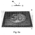
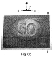
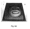
- Figures 6a to 6d are greyscale photographs taken along the same four different viewing angles as in Figures 5a to 5d of a magnetically-induced pattern representing the value "50" within an oval shape, identical to that of Figures 5a to 5d , with the additional provision that, during exposure of the layer of coating composition P, the main direction of the magnetic field lines was rotated by 360°.
- Figures 7a to 7d are four photographs taken along the same four different viewing angles as those of Figures 5a to 5d and 6a to 6d , of another example of a magnetically-induced pattern.
- the main direction of the magnetic field was also rotated by 360° during exposure of the coating composition P.
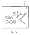
- Figure 7e is a schematic top view of the engraved body 20 which was used in the context of the example shown in Figures 7a to 7d .
- the layer 21 of the body 20 was engraved with a pattern of engravings 211, 212 representing, on the one hand, a stylised representation of a Pegasus 211 and, on the other hand, the words "KBA GIORI" 212.
- the rectilinear or curvilinear patterns 211, 212 where engraved with a line width of approximately 1 millimeter. Tests have shown that a line width of 1 millimeter or more is preferable in the context of the present invention.
- too dense an engraving pattern is preferably to be avoided, i.e. a line spacing of 1 millimeter or more between neighbouring engravings is to be preferred.
- the thickness of layer 21 should be selected to be greater or equal to 50 ⁇ m, even more preferably in the range of 50 to 500 ⁇ m.
- the thickness of the base plate 22 on the other hand is not critical.
- the tests have shown that the distance between the permanent magnets 31, 32 and the body 20 had some influence on the resulting magnetically-induced pattern.
- the permanent magnets or, alternatively, the electromagnets
- the magnetic force of the magnets also plays a role.
- Electromagnets could be used in lieu of permanent magnets to create the necessary magnetic field. Electromagnets are particularly advantageous in that the magnetic field can be completely suppressed at the end of the exposure, thereby preventing further modification of the orientation of the magnetic or magnetizable particles, especially during removal of the substrate from the surface of the body 20.
- rotation of the main direction of the magnetic field can easily be carried out using electromagnets disposed in a circular arrangement and by electronically switching the orientation of the magnetic field in a manner similar to that performed in the context of the actuation of electric motors. Rotation of the magnetic field using permanent magnets would have to be performed by physical rotation of the permanent magnets themselves (or of the substrate S carrying the layer of coating composition P) during exposure.
- the above-described invention can be implemented by designing the above-described magnetic-field-generating device 10 so as to be disposed on the circumference of a cylindrical body of a printing press as generally taught in International application No. WO 2005/000585 in the name of the present Applicant.
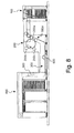
- Figure 8 schematically illustrates one possible embodiment of a sheet-fed printing press as disclosed in International application No. WO 2005/000585 .
- This printing press is adapted to print sheets according to the silk-screen printing process and comprises a feeding station 100 for feeding successive sheets to a silk-screen printing group 200 where silk-screen patterns are applied onto the sheets.
- the printing group 200 comprises an impression cylinder 200a cooperating with two screen cylinders 200b, 200c placed in succession along the printing path of the sheets.
- the freshly printed sheets are transported by means of a conveyor system 300 to a delivery station 400 comprising a plurality of delivery pile units, three in this example.
- the conveyor system 300 is typically an endless chain conveyor system comprising a plurality of spaced-apart gripper bars (not shown in Figure 8 ) extending transversely to the sheet transporting direction, each gripper bar comprising clamping means for holding a leading edge of the sheets.
- a cylinder body 600 carrying a plurality of magnetic-field-generating devices is located along the path of the sheets carried by the chain conveyor system 300.
- This cylinder body 600 is designed to apply a magnetic field to selected locations of the sheets for the purpose of orienting magnetic flakes contained in the patterns of coating composition which have been freshly-applied on the sheets in the printing group 200, as discussed above.
- a drying or curing unit 500 is provided downstream of the cylinder body 600 for drying, respectively curing, the coating composition applied onto the sheets after the magnetic flakes have been oriented and prior to the delivery in the delivery station 400, such unit 500 being typically an infrared drying unit or a UV curing unit depending on the type of coating composition used (e.g. water-based or UV-cured inks/varnishes).
- the cylinder body 600 could alternatively be located at the sheet transfer location 300a between the impression cylinder 200a and the conveyor system 300. Still according to another embodiment envisaged in International application No. WO 2005/000585 , the impression cylinder 200a itself could be designed as a cylinder carrying magnetic-field-generating devices.
- the cylinder body 600 used to orient the magnetic flakes advantageously cooperates with the non-freshly-printed side of the sheets, thereby preventing smearing problems, the magnetic field being applied from the back side of the sheets through the freshly-printed patterns of coating composition.
- the cylinder body 600 is rotated at a circumferential speed corresponding to the speed of the transported sheets so that there is no relative displacement between the transported sheets and the circumference of the cylinder.
- the cylinder body 600 is placed in the path of the chain conveyor system 300 such that the sheets follow a curved path tangential to the outer circumference of the cylinder body 600, thereby enabling part of the surface of the processed sheet to be brought in contact with the outer circumference of the cylinder body 600.
- each printed sheet (or each successive portion of a continuous web, in case of web-printing) carries an array of imprints arranged in a matrix of rows and columns, which imprints ultimately form individual securities after final cutting of the sheets or web portions.
- the cylinder body 600 used to orient the magnetic flakes is therefore typically provided with as many magnetic-field-generating devices as there are imprints on the sheets or web portions.
- the cylinder body 600 is preferably a cylinder body as further taught in EP-A-1 961 559 in the name of the present Applicant.
- the cylinder body advantageously comprises a plurality of distinct annular supporting rings distributed axially along a common shaft member, each annular supporting ring carrying a set of magnetic-field-generating devices which are distributed circumferentially on an outer circumference of the annular supporting rings. Thanks to this cylinder body configuration, the position of each magnetic-field-generating device can be adjusted to the corresponding position of the coating composition imprints on the processed sheets or web.
- the body 20 can be shaped as a curved plate adapted for mounting onto a rotatable cylinder body of a printing press (in such a case, a common plate with engravings could be used for all magnetic-field-generating devices) or, alternatively, as an individual curved plate element adapted for mounting onto a supporting member disposed on the circumference of a cylindrical body of a printing press (in such a case, individual plates would be used).
- the layer of coating composition P is preferably to be printed on a dark background
- any other background is possible such as for example a structured background as discussed in International application WO 2006/061301 .
- a mainly dark background is however preferred in order to yield a better contrast in the resulting magnetically-induced pattern.
Landscapes
- Physics & Mathematics (AREA)
- Engineering & Computer Science (AREA)
- Electromagnetism (AREA)
- Mechanical Engineering (AREA)
- Plasma & Fusion (AREA)
- Business, Economics & Management (AREA)
- Accounting & Taxation (AREA)
- Finance (AREA)
- Printing Methods (AREA)
- Credit Cards Or The Like (AREA)
Claims (16)
- Un dispositif (10) pour transférer magnétiquement des marquages à une couche d'une composition de revêtement (P), telle une encre ou un vernis, appliquée sur au moins une partie de la surface d'un substrat (S), ladite composition de revêtement (P) comprenant au moins un type de particules magnétiques ou magnétisables,
ledit dispositif (10) comprenant un corps (20) soumis à un champ magnétique généré par un moyen électromagnétique, lequel corps (20) porte des marquages déterminés sous la forme de gravures (21a, 21b, 21c ; 211, 212) sur une surface du corps (20), lesquelles gravures (21a, 21b, 21c ; 211, 212) influencent l'orientation des lignes de champ du champ magnétique,
dans lequel ledit corps (20) comprend au moins une couche (21) de matériau de perméabilité magnétique élevée dans laquelle sont formées lesdites gravures (21a, 21b, 21c ; 211, 212), et dans lequel, dans des régions non gravées de ladite couche (21) de matériau de perméabilité magnétique élevée, les lignes de champ du champ magnétique s'étendent essentiellement parallèlement à la surface dudit corps (20) à l'intérieur de ladite couche (21) de matériau de perméabilité magnétique élevée. - Le dispositif selon la revendication 1, dans lequel ledit corps (20) comprend en outre une plaque de base (22) de matériau de faible perméabilité magnétique supportant ladite couche (21) de matériau de perméabilité magnétique élevée,
ladite couche (21) de matériau de perméabilité magnétique élevée étant de préférence déposée sur ladite plaque de base (22) par galvanisation. - Le dispositif selon la revendication 2, dans lequel la perméabilité magnétique de ladite plaque de base (22) se situe dans la gamme de 1.25 à 1.26 µN/A2,
ladite plaque de base (22) étant de préférence constituée d'un matériau non ferromagnétique tel que le cuivre, l'aluminium ou des alliages de ces derniers. - Le dispositif selon l'une quelconque des revendications 1 à 3, dans lequel les gravures (21a, 21b, 21c ; 211, 212) dans ladite couche (21) de matériau de perméabilité magnétique élevée s'étendent à travers toute l'épaisseur de ladite couche (21).
- Le dispositif selon l'une quelconque des revendications 1 à 4, dans lequel la perméabilité magnétique de ladite couche (21) de matériau de perméabilité magnétique élevée est supérieure à 100 µN/A2 (à 0,002 T), de préférence entre 100 et 1000 µN/A2 (à 0,002 T),
ladite couche (21) de matériau de perméabilité magnétique élevée étant de préférence constituée d'un matériau ferromagnétique tel que le fer, le nickel, le cobalt ou des alliages de ces derniers. - Le dispositif selon l'une quelconque des revendications précédentes, dans lequel ladite couche (21) de matériau de perméabilité magnétique élevée présente une épaisseur supérieure ou égale à 50 µm, de préférence entre 50 et 500 µm.
- Le dispositif selon l'une quelconque des revendications précédentes, dans lequel lesdites gravures (21a, 21b, 21c ; 211, 212) comprennent des motifs gravés rectilignes ou curvilignes (211, 212) ayant de préférence une largeur de ligne et/ou un espacement de lignes de 1 millimètre ou plus.
- Le dispositif selon l'une quelconque des revendications précédentes, comprenant au moins un aimant permanent (31, 32) pour générer ledit champ magnétique.
- Le dispositif selon l'une quelconque des revendications 1 à 7, comprenant au moins un électroaimant pour générer ledit champ magnétique.
- Le dispositif selon l'une quelconque des revendications précédentes, dans lequel les lignes de champ dudit champ magnétique, observées perpendiculairement à la surface du corps (20), s'étendent essentiellement le long d'une direction principale (I-II).
- Le dispositif selon l'une quelconque des revendications précédentes, dans lequel ledit corps (20) est façonné comme une plaque incurvée adaptée pour être montée sur un corps cylindrique rotatif (600) d'une presse à imprimer.
- Le dispositif selon l'une quelconque des revendications 1 à 10, dans lequel ledit corps (20) est façonné comme un élément individuel de plaque incurvée adapté pour être monté sur un membre de support disposé sur la circonférence d'un corps cylindrique (600) d'une presse à imprimer.
- Un procédé pour transférer magnétiquement des marquages sur un substrat (S), comprenant les étapes consistant à :(a) appliquer une couche d'une composition de revêtement (P), telle une encre ou un vernis, sur au moins une partie de la surface du substrat (S), ladite composition de revêtement (P) comprenant au moins un type de particules magnétiques ou magnétisables ;(b) alors que la couche de composition de revêtement (P) est encore humide, exposer la couche de composition de revêtement (P) à un champ magnétique déterminé généré à une surface d'un dispositif (10) selon l'une quelconque des revendications précédentes, pour ainsi orienter les particules magnétiques ou magnétisables le long des lignes de champ dudit champ magnétique ; et(c) sécher ou durcir la couche de composition de revêtement (P), pour ainsi fixer l'orientation desdites particules magnétiques ou magnétisables.
- Le procédé selon la revendication 13, dans lequel les lignes de champ dudit champ magnétique, observées perpendiculairement à la surface du corps (20), s'étendent essentiellement le long d'une direction principale (I-II), et dans lequel ladite direction principale des lignes de champ du champ magnétique est modifiée, de préférence tournée de 360°, durant l'exposition de la couche de composition de revêtement (P) à l'étape (b).
- Le procédé selon la revendication 13 ou 14, dans lequel ladite composition de revêtement est appliquée par impression, de préférence par sérigraphie, flexographie ou rotogravure.
- Utilisation du dispositif selon l'une quelconque des revendications 1 à 12 pour induire magnétiquement le transfert de marquages à une composition de revêtement humide (P), telle une encre ou un vernis, appliquée à au moins une partie de la surface d'un substrat (S), laquelle composition de revêtement (P) comprend au moins un type de particules magnétiques ou magnétisables.
Priority Applications (1)
| Application Number | Priority Date | Filing Date | Title |
|---|---|---|---|
| EP08738092.9A EP2155498B1 (fr) | 2007-05-10 | 2008-05-07 | Dispositif et procédé pour transférer magnétiquement un indice vers une composition de revêtement appliquée à un substrat |
Applications Claiming Priority (3)
| Application Number | Priority Date | Filing Date | Title |
|---|---|---|---|
| EP07107966A EP1990208A1 (fr) | 2007-05-10 | 2007-05-10 | Dispositif et procédé pour transférer magnétiquement un indice vers une composition de revêtement appliquée à un substrat |
| EP08738092.9A EP2155498B1 (fr) | 2007-05-10 | 2008-05-07 | Dispositif et procédé pour transférer magnétiquement un indice vers une composition de revêtement appliquée à un substrat |
| PCT/IB2008/051784 WO2008139373A1 (fr) | 2007-05-10 | 2008-05-07 | Dispositif et procédé pour le transfert magnétique de marques à une composition de revêtement appliquée sur un substrat |
Publications (2)
| Publication Number | Publication Date |
|---|---|
| EP2155498A1 EP2155498A1 (fr) | 2010-02-24 |
| EP2155498B1 true EP2155498B1 (fr) | 2014-03-26 |
Family
ID=38515858
Family Applications (2)
| Application Number | Title | Priority Date | Filing Date |
|---|---|---|---|
| EP07107966A Withdrawn EP1990208A1 (fr) | 2007-05-10 | 2007-05-10 | Dispositif et procédé pour transférer magnétiquement un indice vers une composition de revêtement appliquée à un substrat |
| EP08738092.9A Active EP2155498B1 (fr) | 2007-05-10 | 2008-05-07 | Dispositif et procédé pour transférer magnétiquement un indice vers une composition de revêtement appliquée à un substrat |
Family Applications Before (1)
| Application Number | Title | Priority Date | Filing Date |
|---|---|---|---|
| EP07107966A Withdrawn EP1990208A1 (fr) | 2007-05-10 | 2007-05-10 | Dispositif et procédé pour transférer magnétiquement un indice vers une composition de revêtement appliquée à un substrat |
Country Status (6)
| Country | Link |
|---|---|
| US (1) | US8893614B2 (fr) |
| EP (2) | EP1990208A1 (fr) |
| JP (1) | JP5547627B2 (fr) |
| CN (1) | CN101743127B (fr) |
| ES (1) | ES2472740T3 (fr) |
| WO (1) | WO2008139373A1 (fr) |
Cited By (12)
| Publication number | Priority date | Publication date | Assignee | Title |
|---|---|---|---|---|
| WO2018019594A1 (fr) | 2016-07-29 | 2018-02-01 | Sicpa Holding Sa | Procédés de production de couches à effet |
| WO2018033512A1 (fr) | 2016-08-16 | 2018-02-22 | Sicpa Holding Sa | Procédés de production de couches à effets |
| DE102017202747B3 (de) | 2017-02-21 | 2018-08-16 | Koenig & Bauer Ag | Verfahren zur Bearbeitung von Bedruckstoffbogen bei der Herstellung von Wertpapieren sowie Wertpapierdruckmaschine |
| WO2021259527A1 (fr) | 2020-06-23 | 2021-12-30 | Sicpa Holding Sa | Procédés de production de couches à effet optique comprenant des particules pigmentaires magnétiques ou magnétisables |
| WO2022207692A1 (fr) | 2021-03-31 | 2022-10-06 | Sicpa Holding Sa | Procédés de production de couches à effet optique comprenant des particules pigmentaires magnétiques ou magnétisables et présentant un ou plusieurs indices |
| US11577273B2 (en) | 2018-07-30 | 2023-02-14 | Sicpa Holding Sa | Processes for producing optical effects layers |
| WO2023161464A1 (fr) | 2022-02-28 | 2023-08-31 | Sicpa Holding Sa | Procédés de production de couches à effet optique comprenant des particules pigmentaires magnétiques ou magnétisables et présentant un ou plusieurs indices |
| WO2024028408A1 (fr) | 2022-08-05 | 2024-02-08 | Sicpa Holding Sa | Procédés de production de couches à effet optique comprenant des particules de pigment magnétiques ou magnétisables et présentant un ou plusieurs indices |
| WO2024208695A1 (fr) | 2023-04-03 | 2024-10-10 | Sicpa Holding Sa | Appareils et procédés de production de couches à effets optiques |
| WO2024218531A1 (fr) * | 2023-04-20 | 2024-10-24 | Htc Technology Consulting | Alignement magnétique de pigments orientables magnétiquement dans une encre à champs magnétiques superposés. |
| WO2025242569A1 (fr) | 2024-05-22 | 2025-11-27 | Sicpa Holding Sa | Appareils et procédés de production de couches à effets optiques |
| WO2025242568A1 (fr) | 2024-05-22 | 2025-11-27 | Sicpa Holding Sa | Appareils et procédés de production de couches à effet optique |
Families Citing this family (38)
| Publication number | Priority date | Publication date | Assignee | Title |
|---|---|---|---|---|
| DE102010041398A1 (de) * | 2009-10-22 | 2011-04-28 | Manroland Ag | Einrichtung und Verfahren zum Beschichten |
| GB201001603D0 (en) | 2010-02-01 | 2010-03-17 | Rue De Int Ltd | Security elements, and methods and apparatus for their manufacture |
| EP2433798B1 (fr) | 2010-09-24 | 2015-04-08 | KBA-NotaSys SA | Système et procédé d'orientation de paillettes magnétiques contenues dans une encre ou un véhicule vernis appliquées sur un substrat en forme de feuille ou de bande |
| CN102442097A (zh) * | 2010-09-30 | 2012-05-09 | 王玉珠 | 一种磁力印刷方法及其印刷产品 |
| ES2584629T3 (es) * | 2010-12-27 | 2016-09-28 | Viavi Solutions Inc. | Sistema y método para formar una imagen sobre un substrato |
| EP2548658A1 (fr) * | 2011-07-21 | 2013-01-23 | Pago Etikettiersysteme GmbH | Procédé d'impression magnétique et dispositif destiné à l'exécution de celui-ci |
| CN103129195B (zh) * | 2011-11-28 | 2016-05-25 | 珠海格力电器股份有限公司 | 磁性油墨印刷方法 |
| EP4043231B1 (fr) * | 2012-01-12 | 2025-04-30 | Viavi Solutions Inc. | Méthode de fabrication d'un article comprenant de flocons de pigment alignés |
| FR2986181B1 (fr) * | 2012-01-27 | 2014-02-21 | Oreal | Procede de realisation d'un decor sur un materiau support permettant la realisation d'etuis pour l'emballage d'un produit cosmetique |
| CN103386805B (zh) * | 2012-05-09 | 2015-01-21 | 中国人民银行印制科学技术研究所 | 磁定向滚筒 |
| TW201431616A (zh) * | 2013-01-09 | 2014-08-16 | Sicpa Holding Sa | 顯示取決於視角的光學效應之光學效應層;用於其生產之工藝和裝置;攜帶光學效應層之物品;及其用途 |
| CA2890164C (fr) | 2013-01-09 | 2023-01-10 | Sicpa Holding Sa | Couches a effet optique presentant un effet optique dependant de l'angle de vision; procedes et dispositifs pour leur production; articles comportant une couche a effet optique et leurs utilisations |
| CN104129153B (zh) | 2013-03-27 | 2018-06-05 | Viavi 科技有限公司 | 具有虚幻光学效应的光学装置及其制造方法 |
| CN103303019A (zh) * | 2013-06-26 | 2013-09-18 | 常熟印刷厂有限公司 | 一种磁性出版物印刷方法 |
| CN104442055B (zh) * | 2014-11-27 | 2017-07-21 | 惠州市华阳光学技术有限公司 | 一种磁定向图案的制备方法及其制备设备 |
| CN106864014B (zh) * | 2015-12-10 | 2020-02-28 | 惠州市华阳光学技术有限公司 | 一种磁体和磁定向装置 |
| DE102015121822A1 (de) * | 2015-12-15 | 2017-06-22 | Bogen Electronic Gmbh | Gegenstand mit Informationen sowie Verfahren zum Aufbringen und Auslesen der Informationen des Gegenstands |
| AR107681A1 (es) | 2016-02-29 | 2018-05-23 | Sicpa Holding Sa | Aparatos y procesos para producir capas con efecto óptico que comprenden partículas de pigmento no esféricas orientadas magnéticas, o magnetizables |
| KR102612114B1 (ko) | 2016-08-31 | 2023-12-11 | 비아비 솔루션즈 아이엔씨. | 각져 있는 반사성 세그먼트를 갖는 물품 |
| US10357991B2 (en) | 2016-12-19 | 2019-07-23 | Viavi Solutions Inc. | Security ink based security feature |
| CN106965579A (zh) * | 2017-03-20 | 2017-07-21 | 佛山市高明绿色德化工有限公司 | 一种渐变效果的玻璃印刷工艺 |
| FR3067729B1 (fr) * | 2017-06-19 | 2020-05-08 | Gerflor | Procede de realisation d'une couche decor presentant un aspect tridimensionnel |
| CN107471818B (zh) * | 2017-08-07 | 2023-06-13 | 甄欣 | 一种光磁双场形成可变安全图案的系统 |
| TWI772576B (zh) * | 2018-01-17 | 2022-08-01 | 瑞士商西克帕控股有限公司 | 用於生產光學效應層之製程 |
| JP7362982B2 (ja) | 2018-05-08 | 2023-10-18 | シクパ ホルディング ソシエテ アノニム | 非球状配向磁性又は磁化可能顔料粒子を含む光学効果層を生成するための磁気アセンブリ、装置、及びプロセス |
| DE102018004433A1 (de) * | 2018-06-05 | 2019-12-05 | Giesecke+Devrient Currency Technology Gmbh | Verfahren zum Herstellen eines Wertdokuments, Wertdokument und Druckvorrichtung |
| EA202190374A1 (ru) | 2018-07-30 | 2021-06-30 | Сикпа Холдинг Са | Сборки и способы получения слоев с оптическим эффектом, содержащих ориентированные магнитные или намагничиваемые частицы пигмента |
| ES2988654T3 (es) | 2019-02-08 | 2024-11-21 | Sicpa Holding Sa | Conjuntos magnéticos y procesos para producir capas de efecto óptico que comprenden partículas de pigmento magnéticas o magnetizables, oblongas, no esféricas y orientadas |
| CA3134731A1 (fr) | 2019-03-28 | 2020-10-01 | Sicpa Holding Sa | Ensembles magnetiques et procedes de production de couches a effet optique comprenant des particules de pigments magnetiques ou magnetisables non spheriques orientees |
| EP4051440B1 (fr) | 2019-10-28 | 2023-10-04 | Sicpa Holding Sa | Ensembles magnétiques et leurs procédés de production de couches à effet optique comprenant des particules pigmentaires magnétiques ou magnétisables orientées non sphériques |
| BR112022007934A2 (pt) | 2019-10-28 | 2022-07-12 | Sicpa Holding Sa | Montagens magnéticas e processos para produzir camadas de efeito óptico que compreendem partículas de pigmento orientadas não esféricas magnéticas ou magnetizáveis |
| CN110949029A (zh) * | 2019-12-04 | 2020-04-03 | 云南侨通包装印刷有限公司 | 一种分层式磁性光彩漫射效果的制作方法 |
| CN111942060A (zh) * | 2020-08-25 | 2020-11-17 | 彭亮 | 一种浮雕光变防伪元件 |
| CN114633574A (zh) * | 2022-03-24 | 2022-06-17 | 彭亮 | 一种动态视觉立体效果的安全线或条 |
| CN115782385B (zh) * | 2022-12-05 | 2025-10-21 | 惠州市华阳光学技术有限公司 | 一种磁定向装置及印刷设备 |
| CN116393336B (zh) * | 2023-06-09 | 2023-08-18 | 太原科技大学 | 用于磁致伸缩材料薄膜基体旋转涂布的夹具及其使用方法 |
| EP4727776A1 (fr) * | 2024-01-09 | 2026-04-22 | Sun Chemical B.V. | Procédé d'impression à effet 3d |
| DE102024127365A1 (de) | 2024-09-23 | 2026-03-26 | Giesecke+Devrient Currency Technology Gmbh | Verfahren zur Herstellung eines Wertdokuments und Wertdokument |
Family Cites Families (36)
| Publication number | Priority date | Publication date | Assignee | Title |
|---|---|---|---|---|
| US4186944A (en) * | 1974-04-17 | 1980-02-05 | Emi Limited | Security document |
| JPS5656898A (en) * | 1979-10-15 | 1981-05-19 | Takeyoshi Yamaguchi | Printing method using magnetic force |
| JPS6168285A (ja) * | 1984-09-12 | 1986-04-08 | Fuji Photo Film Co Ltd | 印刷方法 |
| US4838648A (en) | 1988-05-03 | 1989-06-13 | Optical Coating Laboratory, Inc. | Thin film structure having magnetic and color shifting properties |
| US5192611A (en) * | 1989-03-03 | 1993-03-09 | Kansai Paint Co., Ltd. | Patterned film forming laminated sheet |
| DE4419173A1 (de) | 1994-06-01 | 1995-12-07 | Basf Ag | Magnetisierbare mehrfach beschichtete metallische Glanzpigmente |
| AU696709B2 (en) | 1995-01-24 | 1998-09-17 | Kba-Notasys Sa | Rotary screen printing machine for sheet printing |
| RU2157764C2 (ru) | 1995-10-20 | 2000-10-20 | Де ля Рю Жиори С.А. | Машина листовой печати |
| JP4023629B2 (ja) | 1996-02-19 | 2007-12-19 | カーベーアー−ジオリ ソシエテ アノニム | 枚葉紙印刷機用圧胴 |
| DE69702504T2 (de) | 1996-03-21 | 2001-04-19 | De La Rue Giori S.A., Lausanne | Siebdruckmaschine |
| US7047883B2 (en) | 2002-07-15 | 2006-05-23 | Jds Uniphase Corporation | Method and apparatus for orienting magnetic flakes |
| US6152035A (en) * | 1999-12-17 | 2000-11-28 | Universal Engraving, Inc. | Magnetic support plate for cladded steel and steel-backed polymer stamping/blocking and embossing graphic arts dies |
| EP1239307A1 (fr) | 2001-03-09 | 2002-09-11 | Sicpa Holding S.A. | Système magnétique d'interférence de couches minces |
| US20020160194A1 (en) | 2001-04-27 | 2002-10-31 | Flex Products, Inc. | Multi-layered magnetic pigments and foils |
| WO2003051633A1 (fr) * | 2001-12-14 | 2003-06-26 | Meccanica Masi | Dispositif d'impression pour machines a imprimer de divers types |
| DE10219845C1 (de) | 2002-05-03 | 2003-11-20 | Koenig & Bauer Ag | Siebdruckmaschine und Siebzylinder |
| EP1369230A1 (fr) * | 2002-06-05 | 2003-12-10 | Kba-Giori S.A. | Procédé de fabrication d'une plaque gravée |
| US7934451B2 (en) * | 2002-07-15 | 2011-05-03 | Jds Uniphase Corporation | Apparatus for orienting magnetic flakes |
| US7258900B2 (en) * | 2002-07-15 | 2007-08-21 | Jds Uniphase Corporation | Magnetic planarization of pigment flakes |
| EP1410923B1 (fr) * | 2002-10-17 | 2006-08-09 | Hell Gravure Systems GmbH | Procédé de production d'une forme d'impression pour la rotogravure |
| JP2004209458A (ja) * | 2002-11-12 | 2004-07-29 | Kansai Paint Co Ltd | 模様塗膜形成方法及び塗装物品 |
| DE10319773B4 (de) | 2003-05-02 | 2006-04-20 | Koenig & Bauer Ag | Siebdruckzylinder |
| WO2005000585A1 (fr) * | 2003-06-30 | 2005-01-06 | Kba-Giori S.A. | Machine d'impression |
| EP1493590A1 (fr) | 2003-07-03 | 2005-01-05 | Sicpa Holding S.A. | Procédé et moyens de production d'un dessin induit par magnétisme dans une composition de revêtement contenant des particules magnétiques |
| DE102004004713A1 (de) * | 2004-01-30 | 2005-09-01 | Leonhard Kurz Gmbh & Co. Kg | Sicherheitselement mit partieller Magnetschicht |
| EP1582349A1 (fr) | 2004-03-30 | 2005-10-05 | Kba-Giori S.A. | Procédé et machine à imprimer |
| EP1588850A1 (fr) | 2004-04-22 | 2005-10-26 | Kba-Giori S.A. | Dispositif de mise en place et de retrait d'une racle dans un cylindre d'impression en serigraphie |
| CA2523648C (fr) | 2004-10-20 | 2014-05-13 | Jds Uniphase Corporation | Alignement dans une encre en pate contenant des particules magnetiques et impression d'effets optiques |
| EP1669213A1 (fr) | 2004-12-09 | 2006-06-14 | Sicpa Holding S.A. | Elément de sécurité avec un aspect dépendent de l'angle d'observation |
| CA2541568C (fr) * | 2005-04-06 | 2014-05-13 | Jds Uniphase Corporation | Dispositifs optiques a changement dynamique d'apparence (dacod) imprimes dans un champ magnetique mis en forme comprenant des structures de fresnel imprimables |
| DE102005019919A1 (de) * | 2005-04-27 | 2006-11-16 | Leonhard Kurz Gmbh & Co. Kg | Verfahren zur Erzeugung von Farbeffektbildern |
| PL1745940T5 (pl) * | 2005-07-20 | 2021-08-02 | Viavi Solutions Inc. | Dwuetapowy sposób pokrywania wyrobu drukowanym obrazem zabezpieczającym |
| CA2568274C (fr) * | 2005-11-18 | 2014-08-12 | Jds Uniphase Corporation | Plaque magnetique d'impression d'effets optiques |
| MX2009004094A (es) * | 2006-10-17 | 2009-05-01 | Sicpa Holding Sa | Metodo y medios para producir indicios magneticamente inducidos en una cubierta que contiene particulas magneticas. |
| EP1961559A1 (fr) | 2007-02-20 | 2008-08-27 | Kba-Giori S.A. | Corps cylindrique d'orientation de paillettes magnétiques contenues dans une encre ou un vernis appliquées sur un substrat en forme de feuille ou de bande |
| EP2025515A1 (fr) * | 2007-08-16 | 2009-02-18 | Kba-Giori S.A. | Imprimante de sérigraphie |
-
2007
- 2007-05-10 EP EP07107966A patent/EP1990208A1/fr not_active Withdrawn
-
2008
- 2008-05-07 US US12/599,353 patent/US8893614B2/en active Active
- 2008-05-07 JP JP2010507043A patent/JP5547627B2/ja active Active
- 2008-05-07 CN CN2008800236318A patent/CN101743127B/zh active Active
- 2008-05-07 EP EP08738092.9A patent/EP2155498B1/fr active Active
- 2008-05-07 WO PCT/IB2008/051784 patent/WO2008139373A1/fr not_active Ceased
- 2008-05-07 ES ES08738092.9T patent/ES2472740T3/es active Active
Cited By (13)
| Publication number | Priority date | Publication date | Assignee | Title |
|---|---|---|---|---|
| WO2018019594A1 (fr) | 2016-07-29 | 2018-02-01 | Sicpa Holding Sa | Procédés de production de couches à effet |
| WO2018033512A1 (fr) | 2016-08-16 | 2018-02-22 | Sicpa Holding Sa | Procédés de production de couches à effets |
| DE102017202747B3 (de) | 2017-02-21 | 2018-08-16 | Koenig & Bauer Ag | Verfahren zur Bearbeitung von Bedruckstoffbogen bei der Herstellung von Wertpapieren sowie Wertpapierdruckmaschine |
| US11577273B2 (en) | 2018-07-30 | 2023-02-14 | Sicpa Holding Sa | Processes for producing optical effects layers |
| EP4230311A1 (fr) | 2018-07-30 | 2023-08-23 | Sicpa Holding SA | Procédés de production de couches à effets optiques |
| WO2021259527A1 (fr) | 2020-06-23 | 2021-12-30 | Sicpa Holding Sa | Procédés de production de couches à effet optique comprenant des particules pigmentaires magnétiques ou magnétisables |
| WO2022207692A1 (fr) | 2021-03-31 | 2022-10-06 | Sicpa Holding Sa | Procédés de production de couches à effet optique comprenant des particules pigmentaires magnétiques ou magnétisables et présentant un ou plusieurs indices |
| WO2023161464A1 (fr) | 2022-02-28 | 2023-08-31 | Sicpa Holding Sa | Procédés de production de couches à effet optique comprenant des particules pigmentaires magnétiques ou magnétisables et présentant un ou plusieurs indices |
| WO2024028408A1 (fr) | 2022-08-05 | 2024-02-08 | Sicpa Holding Sa | Procédés de production de couches à effet optique comprenant des particules de pigment magnétiques ou magnétisables et présentant un ou plusieurs indices |
| WO2024208695A1 (fr) | 2023-04-03 | 2024-10-10 | Sicpa Holding Sa | Appareils et procédés de production de couches à effets optiques |
| WO2024218531A1 (fr) * | 2023-04-20 | 2024-10-24 | Htc Technology Consulting | Alignement magnétique de pigments orientables magnétiquement dans une encre à champs magnétiques superposés. |
| WO2025242569A1 (fr) | 2024-05-22 | 2025-11-27 | Sicpa Holding Sa | Appareils et procédés de production de couches à effets optiques |
| WO2025242568A1 (fr) | 2024-05-22 | 2025-11-27 | Sicpa Holding Sa | Appareils et procédés de production de couches à effet optique |
Also Published As
| Publication number | Publication date |
|---|---|
| JP2010526683A (ja) | 2010-08-05 |
| EP1990208A1 (fr) | 2008-11-12 |
| US20110290129A1 (en) | 2011-12-01 |
| EP2155498A1 (fr) | 2010-02-24 |
| US8893614B2 (en) | 2014-11-25 |
| ES2472740T3 (es) | 2014-07-03 |
| CN101743127B (zh) | 2012-02-29 |
| CN101743127A (zh) | 2010-06-16 |
| WO2008139373A1 (fr) | 2008-11-20 |
| JP5547627B2 (ja) | 2014-07-16 |
Similar Documents
| Publication | Publication Date | Title |
|---|---|---|
| EP2155498B1 (fr) | Dispositif et procédé pour transférer magnétiquement un indice vers une composition de revêtement appliquée à un substrat | |
| KR101411725B1 (ko) | 자성 입자를 함유한 코팅 내의 자기 유도 표식의 제조 방법 및 수단 | |
| EP3059019B1 (fr) | Image obtenue par un procède d'orientation des paillettes magnétiques | |
| US8286551B2 (en) | Printing machine | |
| EP2531357B1 (fr) | Eléments de sécurité et procédés et appareil de fabrication associés | |
| EP2308608B1 (fr) | Appareil pour orienter des paillettes magnétiques | |
| KR102726829B1 (ko) | 배향된 자성 또는 자화성 안료 입자를 포함하는 광학 효과층을 제조하는 조립체 및 방법 | |
| CA2530153A1 (fr) | Procede et moyen pour former un motif induit magnetiquement dans un revetement comprenant des particules magnetiques | |
| TW202532145A (zh) | 用於產生光學效應層的製程 | |
| TW202532144A (zh) | 用於產生光學效應層的製程 | |
| AU2015200595B2 (en) | Security elements and methods and apparatus for their manufacture | |
| HK1228333B (en) | Image obtained by a method for orienting magnetic flakes | |
| TH73153A (th) | วิธีการและวิถีทางสำหรับการผลิตแบบแผนชนิดผ่านการเหนี่ยวนำทางแม่เหล็กไปในผิวเคลือบซึ่งมีอนุภาคแม่เหล็ก | |
| HK1174009B (en) | Security elements and methods and apparatus for their manufacture | |
| TH38276B (th) | วิธีการและวิถีทางสำหรับการผลิตแบบแผนชนิดผ่านการเหนี่ยวนำทางแม่เหล็กไปในผิวเคลือบซึ่งมีอนุภาคแม่เหล็ก | |
| HK1198153B (en) | Security elements |
Legal Events
| Date | Code | Title | Description |
|---|---|---|---|
| PUAI | Public reference made under article 153(3) epc to a published international application that has entered the european phase |
Free format text: ORIGINAL CODE: 0009012 |
|
| 17P | Request for examination filed |
Effective date: 20091111 |
|
| AK | Designated contracting states |
Kind code of ref document: A1 Designated state(s): AT BE BG CH CY CZ DE DK EE ES FI FR GB GR HR HU IE IS IT LI LT LU LV MC MT NL NO PL PT RO SE SI SK TR |
|
| AX | Request for extension of the european patent |
Extension state: AL BA MK RS |
|
| DAX | Request for extension of the european patent (deleted) | ||
| RAP1 | Party data changed (applicant data changed or rights of an application transferred) |
Owner name: KBA-NOTASYS SA |
|
| 17Q | First examination report despatched |
Effective date: 20130419 |
|
| REG | Reference to a national code |
Ref country code: DE Ref legal event code: R079 Ref document number: 602008031116 Country of ref document: DE Free format text: PREVIOUS MAIN CLASS: B41M0005000000 Ipc: B41M0003140000 |
|
| GRAP | Despatch of communication of intention to grant a patent |
Free format text: ORIGINAL CODE: EPIDOSNIGR1 |
|
| RIC1 | Information provided on ipc code assigned before grant |
Ipc: B41M 7/00 20060101ALI20130918BHEP Ipc: B41M 3/14 20060101AFI20130918BHEP |
|
| INTG | Intention to grant announced |
Effective date: 20131016 |
|
| GRAS | Grant fee paid |
Free format text: ORIGINAL CODE: EPIDOSNIGR3 |
|
| GRAA | (expected) grant |
Free format text: ORIGINAL CODE: 0009210 |
|
| AK | Designated contracting states |
Kind code of ref document: B1 Designated state(s): AT BE BG CH CY CZ DE DK EE ES FI FR GB GR HR HU IE IS IT LI LT LU LV MC MT NL NO PL PT RO SE SI SK TR |
|
| REG | Reference to a national code |
Ref country code: GB Ref legal event code: FG4D |
|
| REG | Reference to a national code |
Ref country code: CH Ref legal event code: EP |
|
| REG | Reference to a national code |
Ref country code: AT Ref legal event code: REF Ref document number: 658756 Country of ref document: AT Kind code of ref document: T Effective date: 20140415 |
|
| REG | Reference to a national code |
Ref country code: IE Ref legal event code: FG4D |
|
| REG | Reference to a national code |
Ref country code: DE Ref legal event code: R096 Ref document number: 602008031116 Country of ref document: DE Effective date: 20140508 |
|
| REG | Reference to a national code |
Ref country code: NL Ref legal event code: T3 |
|
| REG | Reference to a national code |
Ref country code: ES Ref legal event code: FG2A Ref document number: 2472740 Country of ref document: ES Kind code of ref document: T3 Effective date: 20140703 |
|
| REG | Reference to a national code |
Ref country code: SE Ref legal event code: TRGR |
|
| PG25 | Lapsed in a contracting state [announced via postgrant information from national office to epo] |
Ref country code: LT Free format text: LAPSE BECAUSE OF FAILURE TO SUBMIT A TRANSLATION OF THE DESCRIPTION OR TO PAY THE FEE WITHIN THE PRESCRIBED TIME-LIMIT Effective date: 20140326 Ref country code: NO Free format text: LAPSE BECAUSE OF FAILURE TO SUBMIT A TRANSLATION OF THE DESCRIPTION OR TO PAY THE FEE WITHIN THE PRESCRIBED TIME-LIMIT Effective date: 20140626 |
|
| REG | Reference to a national code |
Ref country code: AT Ref legal event code: MK05 Ref document number: 658756 Country of ref document: AT Kind code of ref document: T Effective date: 20140326 |
|
| REG | Reference to a national code |
Ref country code: LT Ref legal event code: MG4D |
|
| PG25 | Lapsed in a contracting state [announced via postgrant information from national office to epo] |
Ref country code: FI Free format text: LAPSE BECAUSE OF FAILURE TO SUBMIT A TRANSLATION OF THE DESCRIPTION OR TO PAY THE FEE WITHIN THE PRESCRIBED TIME-LIMIT Effective date: 20140326 |
|
| PG25 | Lapsed in a contracting state [announced via postgrant information from national office to epo] |
Ref country code: LV Free format text: LAPSE BECAUSE OF FAILURE TO SUBMIT A TRANSLATION OF THE DESCRIPTION OR TO PAY THE FEE WITHIN THE PRESCRIBED TIME-LIMIT Effective date: 20140326 Ref country code: HR Free format text: LAPSE BECAUSE OF FAILURE TO SUBMIT A TRANSLATION OF THE DESCRIPTION OR TO PAY THE FEE WITHIN THE PRESCRIBED TIME-LIMIT Effective date: 20140326 |
|
| PG25 | Lapsed in a contracting state [announced via postgrant information from national office to epo] |
Ref country code: RO Free format text: LAPSE BECAUSE OF FAILURE TO SUBMIT A TRANSLATION OF THE DESCRIPTION OR TO PAY THE FEE WITHIN THE PRESCRIBED TIME-LIMIT Effective date: 20140326 Ref country code: BE Free format text: LAPSE BECAUSE OF FAILURE TO SUBMIT A TRANSLATION OF THE DESCRIPTION OR TO PAY THE FEE WITHIN THE PRESCRIBED TIME-LIMIT Effective date: 20140326 Ref country code: EE Free format text: LAPSE BECAUSE OF FAILURE TO SUBMIT A TRANSLATION OF THE DESCRIPTION OR TO PAY THE FEE WITHIN THE PRESCRIBED TIME-LIMIT Effective date: 20140326 Ref country code: BG Free format text: LAPSE BECAUSE OF FAILURE TO SUBMIT A TRANSLATION OF THE DESCRIPTION OR TO PAY THE FEE WITHIN THE PRESCRIBED TIME-LIMIT Effective date: 20140626 Ref country code: CY Free format text: LAPSE BECAUSE OF FAILURE TO SUBMIT A TRANSLATION OF THE DESCRIPTION OR TO PAY THE FEE WITHIN THE PRESCRIBED TIME-LIMIT Effective date: 20140326 Ref country code: CZ Free format text: LAPSE BECAUSE OF FAILURE TO SUBMIT A TRANSLATION OF THE DESCRIPTION OR TO PAY THE FEE WITHIN THE PRESCRIBED TIME-LIMIT Effective date: 20140326 Ref country code: IS Free format text: LAPSE BECAUSE OF FAILURE TO SUBMIT A TRANSLATION OF THE DESCRIPTION OR TO PAY THE FEE WITHIN THE PRESCRIBED TIME-LIMIT Effective date: 20140726 |
|
| PG25 | Lapsed in a contracting state [announced via postgrant information from national office to epo] |
Ref country code: PL Free format text: LAPSE BECAUSE OF FAILURE TO SUBMIT A TRANSLATION OF THE DESCRIPTION OR TO PAY THE FEE WITHIN THE PRESCRIBED TIME-LIMIT Effective date: 20140326 Ref country code: AT Free format text: LAPSE BECAUSE OF FAILURE TO SUBMIT A TRANSLATION OF THE DESCRIPTION OR TO PAY THE FEE WITHIN THE PRESCRIBED TIME-LIMIT Effective date: 20140326 Ref country code: SK Free format text: LAPSE BECAUSE OF FAILURE TO SUBMIT A TRANSLATION OF THE DESCRIPTION OR TO PAY THE FEE WITHIN THE PRESCRIBED TIME-LIMIT Effective date: 20140326 |
|
| PG25 | Lapsed in a contracting state [announced via postgrant information from national office to epo] |
Ref country code: PT Free format text: LAPSE BECAUSE OF FAILURE TO SUBMIT A TRANSLATION OF THE DESCRIPTION OR TO PAY THE FEE WITHIN THE PRESCRIBED TIME-LIMIT Effective date: 20140728 Ref country code: LU Free format text: LAPSE BECAUSE OF FAILURE TO SUBMIT A TRANSLATION OF THE DESCRIPTION OR TO PAY THE FEE WITHIN THE PRESCRIBED TIME-LIMIT Effective date: 20140507 |
|
| REG | Reference to a national code |
Ref country code: DE Ref legal event code: R097 Ref document number: 602008031116 Country of ref document: DE |
|
| PG25 | Lapsed in a contracting state [announced via postgrant information from national office to epo] |
Ref country code: DK Free format text: LAPSE BECAUSE OF FAILURE TO SUBMIT A TRANSLATION OF THE DESCRIPTION OR TO PAY THE FEE WITHIN THE PRESCRIBED TIME-LIMIT Effective date: 20140326 Ref country code: MC Free format text: LAPSE BECAUSE OF FAILURE TO SUBMIT A TRANSLATION OF THE DESCRIPTION OR TO PAY THE FEE WITHIN THE PRESCRIBED TIME-LIMIT Effective date: 20140326 |
|
| PLBE | No opposition filed within time limit |
Free format text: ORIGINAL CODE: 0009261 |
|
| STAA | Information on the status of an ep patent application or granted ep patent |
Free format text: STATUS: NO OPPOSITION FILED WITHIN TIME LIMIT |
|
| REG | Reference to a national code |
Ref country code: IE Ref legal event code: MM4A |
|
| 26N | No opposition filed |
Effective date: 20150106 |
|
| REG | Reference to a national code |
Ref country code: DE Ref legal event code: R097 Ref document number: 602008031116 Country of ref document: DE Effective date: 20150106 |
|
| PG25 | Lapsed in a contracting state [announced via postgrant information from national office to epo] |
Ref country code: IE Free format text: LAPSE BECAUSE OF NON-PAYMENT OF DUE FEES Effective date: 20140507 |
|
| PG25 | Lapsed in a contracting state [announced via postgrant information from national office to epo] |
Ref country code: SI Free format text: LAPSE BECAUSE OF FAILURE TO SUBMIT A TRANSLATION OF THE DESCRIPTION OR TO PAY THE FEE WITHIN THE PRESCRIBED TIME-LIMIT Effective date: 20140326 |
|
| REG | Reference to a national code |
Ref country code: FR Ref legal event code: PLFP Year of fee payment: 9 |
|
| PG25 | Lapsed in a contracting state [announced via postgrant information from national office to epo] |
Ref country code: GR Free format text: LAPSE BECAUSE OF FAILURE TO SUBMIT A TRANSLATION OF THE DESCRIPTION OR TO PAY THE FEE WITHIN THE PRESCRIBED TIME-LIMIT Effective date: 20140627 |
|
| PG25 | Lapsed in a contracting state [announced via postgrant information from national office to epo] |
Ref country code: HU Free format text: LAPSE BECAUSE OF FAILURE TO SUBMIT A TRANSLATION OF THE DESCRIPTION OR TO PAY THE FEE WITHIN THE PRESCRIBED TIME-LIMIT; INVALID AB INITIO Effective date: 20080507 Ref country code: TR Free format text: LAPSE BECAUSE OF FAILURE TO SUBMIT A TRANSLATION OF THE DESCRIPTION OR TO PAY THE FEE WITHIN THE PRESCRIBED TIME-LIMIT Effective date: 20140326 |
|
| REG | Reference to a national code |
Ref country code: FR Ref legal event code: PLFP Year of fee payment: 10 |
|
| REG | Reference to a national code |
Ref country code: FR Ref legal event code: PLFP Year of fee payment: 11 |
|
| PGFP | Annual fee paid to national office [announced via postgrant information from national office to epo] |
Ref country code: SE Payment date: 20250311 Year of fee payment: 18 |
|
| PGFP | Annual fee paid to national office [announced via postgrant information from national office to epo] |
Ref country code: NL Payment date: 20250523 Year of fee payment: 18 |
|
| PGFP | Annual fee paid to national office [announced via postgrant information from national office to epo] |
Ref country code: DE Payment date: 20250603 Year of fee payment: 18 |
|
| PGFP | Annual fee paid to national office [announced via postgrant information from national office to epo] |
Ref country code: GB Payment date: 20250524 Year of fee payment: 18 Ref country code: ES Payment date: 20250602 Year of fee payment: 18 |
|
| PGFP | Annual fee paid to national office [announced via postgrant information from national office to epo] |
Ref country code: IT Payment date: 20250529 Year of fee payment: 18 |
|
| PGFP | Annual fee paid to national office [announced via postgrant information from national office to epo] |
Ref country code: FR Payment date: 20250520 Year of fee payment: 18 |
|
| PGFP | Annual fee paid to national office [announced via postgrant information from national office to epo] |
Ref country code: MT Payment date: 20250527 Year of fee payment: 18 |
|
| PGFP | Annual fee paid to national office [announced via postgrant information from national office to epo] |
Ref country code: CH Payment date: 20250601 Year of fee payment: 18 |