EP1990318B1 - Procede de traitement d' eau de drainage utilisant un support de fixation - Google Patents
Procede de traitement d' eau de drainage utilisant un support de fixation Download PDFInfo
- Publication number
- EP1990318B1 EP1990318B1 EP07706280.0A EP07706280A EP1990318B1 EP 1990318 B1 EP1990318 B1 EP 1990318B1 EP 07706280 A EP07706280 A EP 07706280A EP 1990318 B1 EP1990318 B1 EP 1990318B1
- Authority
- EP
- European Patent Office
- Prior art keywords
- tank
- sludge
- oxidization
- total
- per day
- Prior art date
- Legal status (The legal status is an assumption and is not a legal conclusion. Google has not performed a legal analysis and makes no representation as to the accuracy of the status listed.)
- Active
Links
Images


Classifications
-
- C—CHEMISTRY; METALLURGY
- C02—TREATMENT OF WATER, WASTE WATER, SEWAGE, OR SLUDGE
- C02F—TREATMENT OF WATER, WASTE WATER, SEWAGE, OR SLUDGE
- C02F3/00—Biological treatment of water, waste water, or sewage
- C02F3/02—Aerobic processes
- C02F3/12—Activated sludge processes
- C02F3/1205—Particular type of activated sludge processes
- C02F3/1221—Particular type of activated sludge processes comprising treatment of the recirculated sludge
-
- C—CHEMISTRY; METALLURGY
- C02—TREATMENT OF WATER, WASTE WATER, SEWAGE, OR SLUDGE
- C02F—TREATMENT OF WATER, WASTE WATER, SEWAGE, OR SLUDGE
- C02F3/00—Biological treatment of water, waste water, or sewage
- C02F3/02—Aerobic processes
- C02F3/10—Packings; Fillings; Grids
-
- C—CHEMISTRY; METALLURGY
- C02—TREATMENT OF WATER, WASTE WATER, SEWAGE, OR SLUDGE
- C02F—TREATMENT OF WATER, WASTE WATER, SEWAGE, OR SLUDGE
- C02F3/00—Biological treatment of water, waste water, or sewage
- C02F3/02—Aerobic processes
- C02F3/12—Activated sludge processes
- C02F3/1236—Particular type of activated sludge installations
- C02F3/1268—Membrane bioreactor systems
-
- C—CHEMISTRY; METALLURGY
- C02—TREATMENT OF WATER, WASTE WATER, SEWAGE, OR SLUDGE
- C02F—TREATMENT OF WATER, WASTE WATER, SEWAGE, OR SLUDGE
- C02F3/00—Biological treatment of water, waste water, or sewage
- C02F3/02—Aerobic processes
- C02F3/12—Activated sludge processes
- C02F3/1236—Particular type of activated sludge installations
- C02F3/1268—Membrane bioreactor systems
- C02F3/1273—Submerged membrane bioreactors
-
- C—CHEMISTRY; METALLURGY
- C02—TREATMENT OF WATER, WASTE WATER, SEWAGE, OR SLUDGE
- C02F—TREATMENT OF WATER, WASTE WATER, SEWAGE, OR SLUDGE
- C02F1/00—Treatment of water, waste water, or sewage
- C02F1/52—Treatment of water, waste water, or sewage by flocculation or precipitation of suspended impurities
- C02F1/5236—Treatment of water, waste water, or sewage by flocculation or precipitation of suspended impurities using inorganic agents
-
- C—CHEMISTRY; METALLURGY
- C02—TREATMENT OF WATER, WASTE WATER, SEWAGE, OR SLUDGE
- C02F—TREATMENT OF WATER, WASTE WATER, SEWAGE, OR SLUDGE
- C02F3/00—Biological treatment of water, waste water, or sewage
- C02F3/02—Aerobic processes
- C02F3/08—Aerobic processes using moving contact bodies
- C02F3/085—Fluidized beds
-
- C—CHEMISTRY; METALLURGY
- C02—TREATMENT OF WATER, WASTE WATER, SEWAGE, OR SLUDGE
- C02F—TREATMENT OF WATER, WASTE WATER, SEWAGE, OR SLUDGE
- C02F3/00—Biological treatment of water, waste water, or sewage
- C02F3/30—Aerobic and anaerobic processes
- C02F3/302—Nitrification and denitrification treatment
-
- Y—GENERAL TAGGING OF NEW TECHNOLOGICAL DEVELOPMENTS; GENERAL TAGGING OF CROSS-SECTIONAL TECHNOLOGIES SPANNING OVER SEVERAL SECTIONS OF THE IPC; TECHNICAL SUBJECTS COVERED BY FORMER USPC CROSS-REFERENCE ART COLLECTIONS [XRACs] AND DIGESTS
- Y02—TECHNOLOGIES OR APPLICATIONS FOR MITIGATION OR ADAPTATION AGAINST CLIMATE CHANGE
- Y02W—CLIMATE CHANGE MITIGATION TECHNOLOGIES RELATED TO WASTEWATER TREATMENT OR WASTE MANAGEMENT
- Y02W10/00—Technologies for wastewater treatment
- Y02W10/10—Biological treatment of water, waste water, or sewage
Definitions
- the present invention relates to a wastewater treatment method relying on a high level wastewater treatment technology, in which an immobilized carrier is used.
- the wastewater treatment method relying on the activated sludge process has been employed mainly.
- the wastewater treatment system can be steadily operated under a condition, in which the BOD volume load is within the range of about 0.3 to 0.8 kg/cm 3 per day, when wastewater is brought into contact with an activated sludge under an aerobic within an aeration tank and is then sedimented within a sedimentation tank while the sludge is in part returned to the aeration tank and is in part withdrawn as an excess sludge.
- the system With the conventional activated sludge process, the system must be operated with the BOD volume load of about 0.3 to 0.8 kg/cm 3 per day, requiring the use of a large aeration tank.
- the BOD volume load of about 0.3 to 0.8 kg/cm 3 per day, requiring the use of a large aeration tank.
- the system operation according to the activated sludge process under such a high BOD volume load not only does the treatment become insufficient, but the settleability decreases, accompanied by difficulty in separating the sludge in the sedimentation tank in the subsequent stage to such an extent as to result in difficulty in operating the system steadily.
- the present invention has been devised to alleviate the foregoing problems and inconveniences and is intended to provide an inexpensive wastewater treatment method, in which the tanks can be downsized and withdrawal of the excess sludge can be minimized.
- the wastewater treatment method of the present invention makes use of an aeration tank in which wastewater is contacted with a particulate carrier under an aerobic condition, a total oxidization tank in which the volume of a sludge developed within the aeration tank is reduced, and a solid-liquid separation equipment for the sludge within the total oxidization tank and includes steps of setting the coefficient of self-oxidization of the sludge flowing into the total oxidization tank to 0.05 (per day) or larger and adding a coagulant to the total oxidization tank to improve the solid-liquid separability of the sludge within the total oxidization tank.
- the rate of growth of the sludge and the rate of self-oxidization of the sludge can be counterbalanced with each other to thereby avoid increase of the sludge.
- the aeration tank will have an increased capacity where the activated sludge is employed in the aeration tank and, also, since the coefficient of self-oxidization of the sludge flowing into the total oxidization tank is extremely small, the total oxidization tank must have a capacity that is twice to six times that required when the carrier is employed in the aeration tank, particularly where an attempt is made to counterbalance the rate of growth of the sludge and the rate of self-oxidization of the sludge with each other.
- the reason for the coefficient of self-oxidization of the activated sludge being low appears, inter alia, that the activated sludge contains protozoa having a smaller coefficient of self-oxidization than that of bacteria and that a sticky material derived to coagulate bacteria is composed of a polymer having a small coefficient of self-oxidization.
- the carrier is employed in such an aeration tank, the aeration tank and the total oxidization tank can be downsized, a problem tends to occur that difficulty is encountered in separating the sludge within the sedimentation tank or the membrane filtration apparatus because the sludge developed within the aeration tank contains a small amount of protozoa and sticky material so that they are dispersed without being spontaneously sedimented.
- the inventors of the present invention have found that the addition of a predetermined amount of the coagulant during the practice of the wastewater treatment under a specific condition can lead to not only downsizing of the equipment and improvement of the solid-liquid separability, but also to a considerable reduction in amount of the sludge withdrawn simultaneously therewith and the present invention is based on this finding. It is indeed surprising that as compared with the conventional technique of adding the coagulant hitherto known in the art, the present invention is effective to achieve the intended object with an extremely small amount of the coagulant added.
- the tanks can be downsized and, yet, the amount of the excess sludge withdrawn can be very small, allowing the wastewater to be treated at a low cost.
- Essential components of the present invention are (1) an aeration tank, (2) a coefficient of self-oxidization, (3) a total oxidization tank, (4) a coagulant and (5) a solid-liquid separation equipment, which will be individually described in detail.
- the aeration tank employed in the practice of the present invention is required to conduct an aeration treatment so that a sludge flowing from the aeration tank into the total oxidization tank has a coefficient of self-oxidization that is 0.05 (per day) or larger. While methods necessary to secure discharged water of a kind, in which the coefficient of self-oxidization of the sludge referred to above is 0.05 (per day) or larger, will be described in detail later, the present invention requires at least an addition of a carrier into the aeration tank of the present invention.
- the capacity of the aeration tank is required to be significantly large, as hereinabove described, because the aeration tank is operated under the activated sludge process. Also, since the activated sludge has a coefficient of self-oxidization which is smaller than that where the carrier is employed in the aeration tank, it is necessary to increase the capacity of the total oxidization tank.
- the manner of use of the carrier within the aeration tank may be either a fluidized bed or a fixed bed, the fluidized bed is preferred in terms of process efficiency.
- the carrier to be added to the aeration tank may be of any kind well known in the art, and a carrier selected from the group consisting of a gel carrier, a plastic carrier and a fibrous carrier or a combination of two or more of them is preferably employed.
- a gel carrier of acetalized polyvinyl alcohol is preferred because of a high processing performance and fluidity.
- the filling factor of the carrier is, in the case of the fluidized bed, preferably within the range of 5 to 50% and, more preferably, within the range of 10 to 30% relative to the capacity of the tank in terms of process efficiency and fluidity.
- the coefficient of self-oxidization is a coefficient that is used in calculating the amount of sludge produced and is a proportion of the sludge reduced by self-oxidization resulting from cannibalism of the sludge per day relative to the total amount of the sludge within the total oxidization tank.
- the coefficient of self-oxidization is generally about 0.02 (per day) although it may vary depending on, for example, the operating condition.
- the carrier is employed in the aeration tank, the sludge tends to be reduced as compared with that of the activated sludge, generally having a coefficient of self-oxidization within the range of 0.05 to 0.1 (per day).
- the coefficient of self-oxidization is determined by injecting an activated sludge or a sludge, of a predetermined sludge concentration, within the aeration tank in which the carrier is used, into a graduated cylinder of 1 L in capacity, measuring the sludge concentration each time a predetermined length of time is passed under an aerobic condition, and dividing the amount of the sludge reduced per length of time passed, by the initial mount of the sludge.
- the coefficient of self-oxidization of the sludge contained in a water discharged from the aeration tank varies depending on the property of the water so discharged, the BOD volume load of the aeration tank, the kind and property of the carrier used, temperature, pH and so on. So long as the kind and property of the carrier are concerned, it has been found that it tends to vary considerably depending on the pore size of pores present in the surface of the carrier.
- the pore size of the pores present in the surface of the carrier the pore size is defined as d ⁇ m or smaller when the area of pores of a specific pore size (d ⁇ m) or smaller, measured by electron microscopic observation, occupies 70% or more of the total surface area of the pores.
- the water to be discharged which has a coefficient of self-oxidization as defined in the present invention, can be determined by evaluation using carriers having respective pore sizes of not larger than 10 ⁇ m, not larger than 20 ⁇ m, not larger than 50 ⁇ m and not larger than 100 ⁇ m during pilot experiments conducted under a specific BOD volume load.
- the use of the carrier having a pore size not larger than 50 ⁇ m and, more preferably not larger than 20 ⁇ m, is preferred. The reason therefor is not clear, but it appears that the inhabitancy of microbes that adhere to the carrier is closely related.
- the BOD volume load (often expressed by s-BOD volume load) of the aeration tank
- the tank is operated under the BOD volume load of 2 to 3 (kg/m 3 per day).
- the tank is sequentially operated under conditions of 3 to 4, 4 to 5 and larger than 5 (kg/m 3 per day).
- the temperature with the ranges of 3 to 40°C, preferably 10 to 35°C and more preferably 20 to 30 °C is employed in terms of the biological reactivity.
- the pH value in terms of the biological reactivity, the pH value within the range of 3 to 9, preferably 4 to 8, more preferably 6 to 8 and most preferably 6 to 7 can be suitably employed.
- Methods used to increase the coefficient of self-oxidization of the sludge contained in the water discharged from the aeration tank to a value equal to or larger than 0.05 (per day) is affected by the property of the wastewater to be treated and, therefore, in the practice of the wastewater treatment in accordance; with the present invention, a proper condition under which a given wastewater treatment is carried out varies. Accordingly, pilot experiments have to be carried out so that the BOD volume load of the aeration tank, the kind of the carrier to be used, the pore size of pores present particularly in the surface of the carrier, temperature and pH value should be adjusted in dependence on the property of the wastewater to be treated.
- the concentration of the sludge within the total oxidization tank varies according to the mode of solid-liquid separation that takes place in the subsequent stage.
- the concentration of the sludge within the total oxidization tank is, although not specifically limited thereto, preferably within the range of 3000 to 6000 mg/L and more preferably higher than 6000 mg/L.
- the concentration of the sludge within the total oxidization tank is preferably within the range of 6000 to 10000 mg/L and more preferably higher than 10000 mg/L in order to reduce the capacity of the total oxidization tank.
- the rate of growth of the sludge and the rate of self-oxidization of the sludge are counterbalanced with each other by allowing the sludge to be aerated under a low sludge load to thereby prevent proliferation of the sludge and, hence, the wastewater treatment with minimized withdrawal of the excess sludge can be accomplished.
- condition in which the withdrawal of the excess sludge is minimized means the condition in which the MLSS within the total oxidization tank is substantially constant, the top interface of the sludge in the sedimentation tank to which the water to be discharged is supplied from the total oxidization tank, does not ascend substantially and the withdrawal of the sludge need not be continued more than one day.
- the amount of the sludge that increases per day is smaller than 1% of the total amount of the sludge within the total oxidization tank, it may be said that the withdrawal of the excess sludge is minimal.
- the coagulant employed in the practice of the present invention is intended to improve the sedimentation of the sludge produced within the aeration tank and also to increase the sludge concentration within the total oxidization tank.
- the addition of the coagulant is carried out in one of two ways in which a coagulant reacting tank is provided at a stage between the aeration tank and the total oxidization tank or between the total oxidization tank and the solid-liquid separation equipment so that the coagulant is added directly into the coagulant reacting tank, or, the coagulant is added directly into the total oxidization tank.
- the amount of the coagulant to be added is preferably of a value enough to allow the SVI of the sludge within the total oxidization tank to attain not larger than 200 ml/g.
- the solid-liquid separation equipment employed in the practice of the present invention may be a sedimentation tank or a filtering equipment such as, for example, a membrane filter, a sand filter, or a fibrous filter, all of which may be of a type well known in the art.
- a sedimentation tank or a filtering equipment such as, for example, a membrane filter, a sand filter, or a fibrous filter, all of which may be of a type well known in the art.
- the operating condition including, for example, surface loading and retention time may be identical with that employed in the practice of the conventional activated sludge process.
- the soluble BOD volume load in the aeration tank 1 is preferably equal to or higher than 1 kg/m 3 per day.
- the term "soluble BOD” referred to above is represented by the BOD obtained by measuring a filtrate after filtration with a membrane filter having a pore size of 0.45 ⁇ m and means BOD with microbes removed. (The soluble BOD may be often expressed by "s-BOD" in the subsequent description.) The higher the soluble BOD volume load, the more compact the aeration tank 1 can be assembled.
- the tank can be operated under a load of 2 kg/(m 3 per day) or higher or a load of 5 kg/(m 3 per day) or higher.
- the throughput of the soluble BOD within the aeration tank 1 is preferably equal to or higher than 90%.
- the BOD sludge load in the total oxidization tank 3, in which the sludge can be reduced in volume under an aerobic condition is preferably equal to or lower than 0.05 kg-BOD/(kg-SS per day).
- the wastewater treated under the aerobic condition within the aeration tank 1 is introduced into the total oxidization tank 3 and the coagulant is then added to such total oxidization tank 3, in which any coagulant that can be employed in the standard water treatment can be employed.
- any coagulant that can be employed in the standard water treatment can be employed.
- aluminum sulfate, polyaluminum chloride (PAC), ferrous sulfate, ferric sulfate, ferric chloride, chlorinated copperas, sodium aluminate, ammonium alum, potassium alum, calcium hydroxide, calcium oxide, soda ash, sodium carbonate, magnesium oxide, and an iron-silica polymer can be enumerated.
- polyacrylamide, sodium alginate, carboxymethyl cellulose sodium salt, sodium polyacrylate, a copolymer of maleic acid, water soluble aniline, polythiourea, polyethyleneimine, quaternary ammonium salt, polyvinyl pyridines, polyoxyethylene, and caustic starch can be enumerated.
- the coagulant consisting of two or more of those substances can also be employed in the practice of the present invention.
- the coagulant is added until the SVI, which is an index of sedimentation of the sludge, attains a value equal to or smaller than 200 ml/g.
- the addition of the coagulant can be performed according to either an intermittent addition method, in which addition of the coagulant continues up until the sedimentation of the sludge can be improved, followed by refrainment of the addition up until the sedimentation of the sludge becomes worse or a continuous addition method in which a small amount of the coagulant is constantly added.
- coagulant requires a specific pH value and a temperature range to be observed for coagulation and may bring about a change in pH value when added. Accordingly, it is preferred to perform a water quality control to adjust the pH value for coagulation, as required.
- nitrate nitrogen and/or nitrite nitrogen derived from microbe are generated and are then carried off by a treated sewage from the sedimentation tank 5.
- a denitrifying tank and a nitrifying tank may be employed in the stage preceding or subsequent to the total oxidization tank 3 and the treated sewage emerging from nitrifying tank or the total oxidization tank 3 may be returned to the denitrifying tank.
- the treated sewage may be returned to the denitrifying tank.
- the flow for the removal of nitrogen is not specifically limited in the practice of the present invention and any known method can be employed such as, for example, the Wuhmann's method, in which the nitrifying tank and the denitrifying tank are arranged sequentially in this order and the Barnard's method, in which while the denitrifying tank and the nitrifying tank are arranged sequentially in this order, the sewage is returned from the nitrifying tank to the denitrifying tank and an organic matter such as methanol or the like is added as a source of nutrition for denitrifying bacteria.
- an organic matter such as methanol or the like is added as a source of nutrition for denitrifying bacteria.
- a combination of those methods may also be employed.
- the sludge may be contacted with nitrifying bacteria within the nitrifying tank under an aerobic condition with the BOD sludge load being equal to or lower than 0.08 kg-BOD/Kg-MLSS per day and the nitrifying step at which the sludge is allowed to undergo self-oxidization and the total oxidizing step are carried out within one and the same tank.
- the separating membrane that can be employed in the practice of the present invention may not be always limited to a specific shape, but may have any suitable shape selected from a hollow fiber membrane, a tubular membrane and a flat membrane, and where the hollow fiber membrane is employed, a relatively large membrane area per unitary capacity of the membrane can be obtained and a filtering device can be downsized.
- the separating membrane that can be employed in the practice of the present invention is not always limited to that made of a specific material, but the membrane made of, for example, an organic polymeric material such as, for example, polyolefm, polysulfone, polyethersulfone, ethylene-vinyl alcohol copolymer, polyacrylonitrile, cellulose acetate, polyvinylidene fluoride, polyperfluoroethylene, polyester methacrylate, polyester or polyamide, or the membrane made of an inorganic material such as, ceramics may be suitable employed in consideration of, for example, the condition of use and the desired filtering performance.
- an organic polymeric material such as, for example, polyolefm, polysulfone, polyethersulfone, ethylene-vinyl alcohol copolymer, polyacrylonitrile, cellulose acetate, polyvinylidene fluoride, polyperfluoroethylene, polyester methacrylate, polyester or polyamide
- the membrane made of an inorganic material such as, ceramic
- the membrane made of a hydrophilic material such as a polysulfone resin hydrophilized with a polyvinyl alcohol resin, a polysulfone resin added with a hydrophilic polymer, a polyvinyl alcohol resin, a polyacrylonitrile resin, a cellulose acetate resin, or a polyethylene resin which has been hydrophilized is preferably employed since due to a high hydrophilic property sufficient to minimize adherence of SS components and to enhance separation of adhered SS components, but the hollow fiber membrane made of any other material may be also employed.
- the organic polymer material it may be a copolymer of a plurality of polymers or a blended material consisting of a plurality of the materials may be employed.
- a manufacturing method is not specifically limited to a particular one, but a method selected suitably from any known methods may be employed in consideration of the characteristics of the material and the desired shape and performance of the separation membrane to be used.
- the pore size of the separation membrane that may be employed in the practice of the present invention is preferably not greater than 5 ⁇ m in consideration of the separating performance between the sludge and water.
- the pore size of the separation membrane within the range of 0.1 to 3 ⁇ m is more preferable.
- the pore size referred to hereinbefore and hereinafter is defined as a particle size of a particular reference material at which particle size 90% of the particles of the reference material is eliminated by filtering of the separation membrane.
- the reference material has a known particle size and may be selected from various materials such as, for example, colloidal silica, emulsion or latex.
- the pore size is preferably uniform over the separation membrane.
- the ultra filtration membrane having a molecular weight cutoff greater than 3000 may be preferably employed.
- the separation membrane is employed in a modularized form for filtration.
- any mode of modularization may be suitably selected, and a hollow fiber membrane module may be constructed by mounting one or a plurality of membrane elements.
- a membrane module in which several tens to some hundred thousands of hollow fiber membranes that are bundled together are bent to represent a generally U-shaped configuration and then accommodated within a module, a membrane module in which one end of the bundle of the hollow fibers is sealed by a suitable sealing member, a membrane module in which a bundle of hollow fibrous filaments are respectively sealed at one end by suitable sealing members in a state left not connected at one end together (in a free state), and a membrane module in which opposite ends of the bundle of hollow fibrous filaments are left open, may be employed.
- the present invention is not intended to limit to a specific shape and the membrane module may represent, for example, a cylindrical shape or a screen-like shape.
- the separation membrane can be regenerated when physically or chemically cleansed.
- the regenerating condition may be suitably selected depending on the material forming the separation membrane module, the shape thereof and/or the pore size of the separation membrane used.
- the physical cleansing method of the hollow fiber membrane module may include, for example, back washing of the membrane filter with water, back washing with gas, flushing, or air bubbling while the chemical cleansing method may include a method in which the separation filter is washed with acid such as hydrochloric acid, sulfuric acid, nitric acid, oxalic acid or citric acid, cleansing with alkaline such as, sodium hydrate, cleansing with an oxidizing agent such as sodium hypochlorite or hydrogen peroxide, or a cleansing with a chelating agent such as ethylene diamine tetra-acetic acid may be employed.
- acid such as hydrochloric acid, sulfuric acid, nitric acid, oxalic acid or citric acid
- cleansing with alkaline such as, sodium hydrate
- cleansing with an oxidizing agent such as sodium hypochlorite or hydrogen peroxide
- a cleansing with a chelating agent such as ethylene diamine tetra-acetic acid
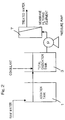
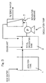
- the filtering system may be employed in the form of a system in which as shown in Fig. 2 , the membrane module (membrane filtering device) 7 or the like including the separation membrane is disposed outside the total oxidization tank 3 and a raw water containing a sludge is supplied to the membrane module 7 or the like for total filtration, a system in which as shown in Fig.
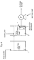
- the membrane module 7 or the like including the separation membrane is disposed outside the total oxidization tank 3 and a raw water containing a sludge is circulated so that a portion of the raw water can be filtered, and a system in which as shown in Fig. 4 , the membrane module 7 or the like including the separation membrane is submerged within the total oxidization tank 3 and a raw water containing a sludge is sucked therethrough for filtration.
- the water head difference may be employed in place of a pressure pump or a suction pump. It is to be noted that the system shown in Fig.
- the system shown in Fig. 4 has such advantages that the space for installation may be small and the energy can be small, but has such a disadvantage that the permeate flux is generally low enough to require a large membrane surface area. Also, where the system is employed in which the separation membrane is immersed within the total oxidization tank 3 and filtration is carried out by the utilization of a suction or a water head difference as shown in Fig.
- the membrane module 7 or the like including the separation membrane is placed atop an air diffusing device so that membrane clogging can be suppressed by the utilization of an effect of cleansing the membrane surface with diffused air.
- a wastewater treating equipment may be newly installed for the purpose of the present invention, but any existing wastewater treating equipment may be renovated.
- BOD removal ratio Raw Water BOD ⁇ Soluble BOD of Discharged Water / Raw Water BOD ⁇ 100 (SS)
- the wastewater was filtered through a 0.45 ⁇ m filter and was then dried.
- the weight of the filter before treatment was subtracted from the weight of the dried filter to provide the weight of a solid component and was then divided by the volume of the discharged water, for conversion into the concentration.
- the sludge transformation ratio is calculated from the BOD quantity, treated within the test tank, and the quantity of SS generated within the test tank.
- Sludge transformation ratio % SS Quantity / BOD Quantity Removed ⁇ 100
- Example 1 The dry weight of the quantity of the sludge withdrawn is described.
- Example 1 The dry weight of the quantity of the sludge withdrawn is described.
- a gel carrier of acetalized polyvinyl alcohol having a pore size of not greater than 20 ⁇ m was supplied into a test tank of 1000 ml in capacity and chemical wastewater A was supplied into the test tank in such a quantity that the BOD volume load of 3.5 kg/(m 3 per day) can be established. From the SS concentration within the wastewater measured at the time the BOD removal ratio in the test tank attained 95% or higher, the sludge transformation ratio of 10% was obtained. Thereafter, the SS was filled in a graduated cylinder of 1 L in capacity and the coefficient of self-oxidization was subsequently determined in reference to a time-dependent change of the sludge concentration under an aerobic condition. The coefficient of self-oxidization so measured was found to be 0.082 (per day).
- an experiment to treat the chemical wastewater A of 400 m 3 per day was conducted with the use of a wastewater treatment equipment including the aeration tank 1 having a capacity of 230 m 3 , the total oxidization tank 3 having a capacity of 100 m 3 and the sedimentation tank 5 having a capacity of 50 m 3 .
- the gel carrier of acetalized polyvinyl alcohol having a pore size of not greater than 20 ⁇ m was charged in a quantity of 23 m 3 into the aeration tank 1.
- Polychlorinated aluminum (an inorganic coagulant) was added to the total oxidization tank 3 to the extent that the solid-liquid separability of the sludge within the sedimentation tank 5 was improved.
- the MLSS within the total oxidization tank 3 increased gradually, and then attained at a substantially constant value of about 10000 mg/L.
- the sludge transformation ratio in the aeration tank 1 was found to be 10%.
- the coefficient of self-oxidization derived from the quantity of the sludge flowing into the total oxidization tank 3 and the quantity of the sludge reduced within the total oxidization tank 3 at the time the MLSS within the total oxidization tank 3 , was found to be 0.080, which is substantially identical with the result of the preparatory experiment.
- a gel carrier of acetalized polyvinyl alcohol having a pore size of not greater than 20 ⁇ m was supplied into a test tank of 1000 ml in capacity and chemical wastewater A was supplied into the test tank in such a quantity that the BOD volume load of 2.5 kg/(m 3 per day) can be established. From the SS concentration within the wastewater measured at the time the BOD removal ratio in the test tank attained 95% or higher, the sludge transformation ratio of 10% was obtained. Thereafter, the SS was filled in a graduated cylinder of 1 L in capacity and the coefficient of self-oxidization was subsequently determined in reference to a time-dependent change of the sludge concentration under an aerobic condition. The coefficient of self-oxidization so measured was found to be 0.034 (per day).
- an experiment to treat the chemical wastewater A of 400 m 3 per day was conducted with the use of a wastewater treatment equipment including the aeration tank 1 having a capacity of 320 m 3 , the total oxidization tank 3 having a capacity of 100 m 3 and the sedimentation tank 5 having a capacity of 50 m 3 .
- the gel carrier of acetalized polyvinyl alcohol having a pore size of not greater than 20 ⁇ m was charged in a quantity of 32 m 3 into the aeration tank 1.
- Polychlorinated aluminum (an inorganic coagulant) was added to the total oxidization tank 3 to the extent that the solid-liquid separability of the sludge within the sedimentation tank 5 was improved.
- the sludge transformation ratio in the aeration tank 1 was found to be 10%.
- the MLSS within the total oxidization tank 3 increased gradually and attained at a substantially constant value of about: 10000 mg/L, but the interface of the sludge within the sedimentation tank 5 increased day by day and withdrawal of the sludge in a quantity of about 47 kg per day was needed.
- the coefficient of self-oxidization derived from the quantity of the sludge generated within the total oxidization tank 3 and the quantity of the sludge withdrawn, was found to be 0.033 (per day).
- an experiment to treat the chemical wastewater A of 400 m 3 per day was conducted with the use of a wastewater treatment equipment including the aeration tank 1 having a capacity of 320 m 3 , the total oxidization tank 3 having a capacity of 240 m 3 and the sedimentation tank 5 having a capacity of 50 m 3 .
- the gel carrier of acetalized polyvinyl alcohol having a pore size of not greater than 20 ⁇ m was charged in a quantity of 32 m 3 into the aeration tank 1.
- Polychlorinated aluminum an inorganic coagulant
- the MLSS within the total oxidization tank 3 increased gradually and attained at a substantially constant value of about 10000 mg/L.
- the sludge transformation ratio in the aeration tank 1 was found to be 10%.
- the coefficient of self-oxidization derived from the quantity of the sludge flowing into the total oxidization tank 3 and the quantity of the sludge reduced within the total oxidization tank 3 at the time the MLSS within the total oxidization tank 3 , was found to be 0.033 (per day), which is substantially identical with the result of the preparatory experiment.
- the use of the total oxidization tank 3 having a capacity twice or more the capacity of the total oxidization tank 3 used in Example 1 is required and, hence, it has become clear that in accordance with the wastewater treatment method of the present invention, the wastewater can be treated with the apparatus of a smaller capacity.
- a gel carrier of acetalized polyvinyl alcohol having a pore size of not greater than 20 ⁇ m was supplied into a test tank of 1000 ml in capacity and chemical wastewater B was supplied into the test tank in such a quantity that the BOD volume load of 2.5 kg/(m 3 per day) can be established From the SS concentration exhibited when the BOD removal ratio within the tank attained 95% or higher, the sludge transformation ratio of 30% was obtained. Thereafter, the SS was filled in a graduated cylinder of 1 L in capacity and the coefficient of self-oxidization subsequently determined in reference to a time-dependent change of the sludge concentration under an aerobic condition! was found to be 0.070 (per day).
- Polychlorinated aluminum (an inorganic coagulant) was added to the total oxidization tank 3 to the extent that the solid-liquid separability of the sludge within the sedimentation tank 5 was improved.
- the membrane filtering device was operated according to a suction filtering system, in which a hollow fiber membrane module 7 having a pore size of 0.4 ⁇ m was immersed within the total oxidization 3 and aeration was carried out for constant cleansing of the membrane.
- the MLSS within the total oxidization tank 3 increased gradually, and then attained at a substantially constant value of about 11000 mg/L.
- the sludge transformation ratio in the aeration tank 1 was found to be 30%. Also, the coefficient of self-oxidization, derived from the quantity of the sludge flowing into the total oxidization tank 3 and the quantity of the sludge reduced within the total oxidization tank 3 at the time the MLSS within the total oxidization tank 3 , was found to be 0.073, which is substantially identical with the result of the preparatory experiment.
- 100 ml of a gel carrier of acetalized polyvinyl alcohol having a pore size of not greater than 100 ⁇ m was supplied into a test tank of 1000 ml in capacity and chemical wastewater B was supplied into the test tank in such a quantity that the BOD volume load of 2.5 kg/(m 3 per day) can be established. From the SS concentration within the wastewater measured at the time the BOD removal ratio in the test tank attained 95% or higher, the sludge transformation ratio of 30% was obtained. Thereafter, the SS was filled in a graduated cylinder of 1 L in capacity and the coefficient of self-oxidization was subsequently determined in reference to a time-dependent change of the sludge concentration under an aerobic condition. The coefficient of self-oxidization so measured was found to be 0.025 (per day).
- the membrane filtering device was operated according to a suction filtering system, in which a hollow fiber membrane module 7 having a pore size of 0.4 ⁇ m was immersed within the total oxidization 3 and aeration was carried out for constant cleansing of the membrane.
- a suction filtering system in which a hollow fiber membrane module 7 having a pore size of 0.4 ⁇ m was immersed within the total oxidization 3 and aeration was carried out for constant cleansing of the membrane.
- the sludge transformation ratio in the aeration tank 1 was found to be 30%.
- the MLSS within the total oxidization tank 3 was set to about 11000 mg/L as is the case with that in Example 2.
- the sludge within the total oxidization tank 3 was needed to be withdrawn in a quantity of about 155 kg per day.
- the coefficient of self-oxidization was found to be 0.026 (per day).
- an experiment to treat the artificial wastewater of 1200 L per day was conducted with the use of a wastewater treatment equipment including the denitrifying tank 9 having a capacity of 200 L, the nitrifying tank 11 having a capacity of 200 L, the total oxidization tank 3 having a capacity of 200 L and the sedimentation tank 5 having a capacity of 150 L.
- the artificial wastewater was prepared to have a BOD of 200 mg/L and total nitrogen of 50 mg/L.
- the MLSS in the total oxidization tank 3 increased gradually, having attained at a constant value of about 5200 mg/L.
- the sludge transformation ratio in the denitrifying tank 9 and the nitrifying tank 11 was found to be 30%.
- the coefficient of self-oxidization, derived from the quantity of the sludge flowing into the total oxidization tank 3 and the quantity of the sludge reduced within the total oxidization tank 3 at the time the MLSS within the total oxidization tank 3, was found to be 0.069 per day, which is substantially identical with the result of the preparatory experiment.
- an experiment to treat the artificial wastewater of 1200 L per day was conducted with the use of a wastewater treatment equipment similar to that employed in Example 3.
- the artificial wastewater was prepared to have a BOD of 200 mg/L and total nitrogen of 50 mg/L.
- 20 L of the gel carrier of acetalized polyvinyl alcohol having a pore size of not greater than 100 ⁇ m was charged into each of the denitrifying tank 9 and the nitrifying tank 11.
- a liquid within the nitrifying tank 11 was returned to the denitrifying tank 9 at a rate of 3600 L per day.
- an experiment to treat the food wastewater of 200 m 3 per day was conducted with the use of a wastewater treatment equipment including the aeration tank 1 having a capacity of 70 m 3 , the total oxidization tank 3 having a capacity of 190 m 3 and the sedimentation tank 5 having a capacity of 25 m 3 . 7 m 3 of the gel carrier of acetalized polyvinyl alcohol having a pore size of not greater than 20 ⁇ m was charged into the aerating tank 1.
- Polychlorinated aluminum an inorganic coagulant
- the MLSS within the total oxidization tank 3 increased gradually and attained at a substantially constant value of about 6000 mg/L.
- the sludge transformation ratio in the aeration tank 1 was found to be 40%.
- the coefficient of self-oxidization derived from the quantity of the sludge flowing into the total oxidization tank 3 and the quantity of the sludge reduced within the total oxidization tank 3 at the time the MLSS within the total oxidization tank 3 , was found to be 0.070 (per day), which is substantially identical with the result of the preparatory experiment.
- a gel carrier of acetalized polyvinyl alcohol having a pore size of not greater than 100 ⁇ m was supplied into a test tank of 1000 ml in capacity and food wastewater A was supplied into the test tank in such a quantity that the BOD volume load of 3.0 kg/(m 3 per day) can be established. From the SS concentration exhibited when the BOD removal ratio within the tank attained 95% or higher, the sludge transformation ratio of 40% was obtained. Thereafter, the SS was filled in a graduated cylinder of 1 L in capacity and when the coefficient of self-oxidization subsequently determined in reference to a time-dependent change of the sludge concentration under an aerobic condition, the coefficient of self-oxidization was found to be 0.024 (per day).
- the sludge transformation ratio in the aeration tank 1 was found to be 40%.
- the MLSS in the total oxidization tank 3 increased gradually, having attained at a constant value of about 6000 mg/L, but the interface of the sludge within the sedimentation tank 5 increased day by day and withdrawal of the sludge in a quantity of about 50 kg per day was needed.
- the coefficient of self-oxidization was measured from the quantity of the sludge generated within the total oxidization tank 3 and the quantity of the sludge withdrawn, the coefficient of self-oxidization was found to be 0.025 (per day).
- an experiment to treat the chemical wastewater C of 400 m 3 per day was conducted with the use of a wastewater treatment equipment including the aeration tank 1 having a capacity of 320 m 3 , the total oxidization tank 3 having a capacity of 570 m 3 and the sedimentation tank 5 having a capacity of 50 m 3 .
- 32 m 3 of the gel carrier of acetalized polyvinyl alcohol having a pore size of not greater than 20 ⁇ m was charged into the aeration tank 1.
- Polychlorinated aluminum an inorganic coagulant
- the MLSS in the total oxidization tank 3 increased gradually, having attained at a constant value of about 6000 mg/L.
- the sludge transformation ratio in the aeration tank 1 was found to be 30%.
- the coefficient of self-oxidization was found to be 0.070 (per day), which was identical with that obtained during the preparatory experiment.
- the sludge transformation ratio in the aeration tank 1 was found to be 30%.
- the MLSS in the total oxidization tank 3 increased gradually, having attained at a constant value of about 6000 mg/L, but the interface of the sludge within the sedimentation tank 5 increased day by day and withdrawal of the sludge in a quantity of about 127 kg per day was needed.
- the coefficient of self-oxidization was measured from the; quantity of the sludge generated within the total oxidization tank 3 and the quantity of the sludge withdrawn, the coefficient of self-oxidization was found to be 0.033 (per day).
- a gel carrier of acetalized polyvinyl alcohol having a pore size of not greater than 100 ⁇ m was supplied into a test tank of 1000 ml in capacity and food wastewater B was supplied into the test tank in such a quantity that the BOD volume load of 5 kg/(m 3 per day) can be established. From the SS concentration exhibited when the BOD removal ratio within the tank attained 95% or higher, the sludge transformation ratio of 30% was obtained. Thereafter, the SS was filled in a graduated cylinder of 1 L in capacity and when the coefficient of self-oxidization subsequently determined in reference to a time-dependent change of the sludge concentration under an aerobic condition, the coefficient of self-oxidization was found to be 0.055 (per day).
- an experiment to treat the food wastewater B of 400 m 3 per day was conducted with the use of a wastewater treatment equipment including the aeration tank 1 having a capacity of 160 m 3 , the total oxidization tank 3 having a capacity of 700 m 3 and the sedimentation tank 5 having a capacity of 50 m 3 .
- 16 m 3 of the gel carrier of acetalized polyvinyl alcohol having a pore size of not greater than 100 ⁇ m was charged into the aeration tank 1.
- Polychlorinated aluminum an inorganic coagulant
- the MLSS in the total oxidization tank 3 increased gradually, having attained at a constant value of about 6000 mg/L.
- the sludge transformation ratio in the aeration tank 1 was found to be 30%.
- a gel carrier of acetalized polyvinyl alcohol having a pore size of not greater than 100 ⁇ m was supplied into a test tank of 1000 ml in capacity and food wastewater B was supplied into the test tank in such a quantity that the BOD volume load of 2.0 kg/(m 3 per day) can be established. From the SS concentration exhibited when the BOD removal ratio within the tank attained 95% or higher, the sludge transformation ratio of 30% was obtained. Thereafter, the SS was filled in a graduated cylinder of 1 L in capacity and when the coefficient of self-oxidization subsequently determined in reference to a time-dependent change of the sludge concentration under an aerobic condition, the coefficient of self-oxidization was found to be 0.020 (per day).
- an experiment to treat the food wastewater B of 400 m 3 per day was conducted with the use of a wastewater treatment equipment including the aeration tank 1 having a capacity of 400 m 3 , the total oxidization tank 3 having a capacity of 700 m 3 and the sedimentation tank 5 having a capacity of 50 m 3 .
- 40 m 3 of the gel carrier of acetalized polyvinyl alcohol having a pore size of not greater than 100 ⁇ m was charged into the aeration tank 1.
- Polychlorinated aluminum (an inorganic coagulant) was added to the total oxidization tank 3 to the extent that the solid-liquid separability of the sludge within the sedimentation tank 5 was improved.
- the sludge transformation ratio in the aeration tank 1 was found to be 30%.
- the MLSS in the total oxidization tank 3 increased gradually, having attained at a constant value of about 6000 mg/L, and the interface of the sludge within the sedimentation tank 5 increased day by day and withdrawal of the sludge in a quantity of about 150 kg per day was needed.
- the coefficient of self-oxidization was measured from the quantity of the sludge generated within the total oxidization tank 3 and the quantity of the sludge withdrawn, the coefficient of self-oxidization was found to be 0.021 (per day).
Landscapes
- Life Sciences & Earth Sciences (AREA)
- Biodiversity & Conservation Biology (AREA)
- Microbiology (AREA)
- Hydrology & Water Resources (AREA)
- Engineering & Computer Science (AREA)
- Environmental & Geological Engineering (AREA)
- Water Supply & Treatment (AREA)
- Chemical & Material Sciences (AREA)
- Organic Chemistry (AREA)
- Biological Treatment Of Waste Water (AREA)
- Activated Sludge Processes (AREA)
- Separation Using Semi-Permeable Membranes (AREA)
- Purification Treatments By Anaerobic Or Anaerobic And Aerobic Bacteria Or Animals (AREA)
- Immobilizing And Processing Of Enzymes And Microorganisms (AREA)
Claims (6)
- Procédé de traitement d'une eau usée réalisé à l'aide d'une cuve d'aération dans laquelle l'eau usée est mise en contact avec un véhicule particulaire dans des conditions aérobies, d'une cuve d'oxydation totale dans laquelle le volume d'une boue développée dans la cuve d'aération est réduit, et un équipement de séparation solide-liquide pour la boue à l'intérieur de la cuve d'oxydation totale, procédé qui comprend les étapes de :fixation d'un coefficient d'auto-oxydation, qui est défini comme étant une proportion de la boue réduite par une auto-oxydation résultant d'un cannibalisme de la boue par jour, par rapport à la quantité totale de la boue à l'intérieur de la cuve d'oxydation totale, de la boue s'écoulant dans la cuve d'oxydation totale de 0,05 (par jour) ou plus ; etaddition d'un coagulant dans la cuve d'oxydation totale pour améliorer la capacité de séparation solide-liquide de la boue à l'intérieur de la cuve d'oxydation totale.
- Procédé de traitement d'une eau usée selon la revendication 1, dans lequel le traitement d'une eau usée dans la cuve d'aération est réalisé pour éliminer la DBO ou pour éliminer l'azote.
- Procédé de traitement d'une eau usée selon la revendication 1, dans lequel la charge en DBO de la boue à l'intérieur de la cuve d'oxydation totale est fixée à 0,05 kg - DBO /(kg - SS par jour) ou moins.
- Procédé de traitement d'une eau usée selon la revendication 1, dans lequel l'équipement de séparation solide-liquide pour la boue à l'intérieur de la cuve d'oxydation totale est sous la forme d'une cuve de sédimentation ou d'un équipement de filtration.
- Procédé de traitement d'une eau usée selon la revendication 1, dans lequel le véhicule est au moins un véhicule choisi dans le groupe constitué d'un véhicule en gel, d'un véhicule en plastique et d'un véhicule fibreux.
- Procédé de traitement d'une eau usée selon la revendication 5, dans lequel le véhicule est un gel de poly(alcool vinylique) acétylé.
Priority Applications (1)
| Application Number | Priority Date | Filing Date | Title |
|---|---|---|---|
| HRP20161387TT HRP20161387T1 (hr) | 2006-01-25 | 2007-01-24 | Postupak obrade otpadne vode uz upotrebu fiksacijskog nosača |
Applications Claiming Priority (3)
| Application Number | Priority Date | Filing Date | Title |
|---|---|---|---|
| JP2006016426 | 2006-01-25 | ||
| JP2006249744 | 2006-09-14 | ||
| PCT/JP2007/000028 WO2007086240A1 (fr) | 2006-01-25 | 2007-01-24 | Procede de traitement d’eau de drainage utilisant un support de fixation |
Publications (3)
| Publication Number | Publication Date |
|---|---|
| EP1990318A1 EP1990318A1 (fr) | 2008-11-12 |
| EP1990318A4 EP1990318A4 (fr) | 2010-03-10 |
| EP1990318B1 true EP1990318B1 (fr) | 2016-09-07 |
Family
ID=38309039
Family Applications (1)
| Application Number | Title | Priority Date | Filing Date |
|---|---|---|---|
| EP07706280.0A Active EP1990318B1 (fr) | 2006-01-25 | 2007-01-24 | Procede de traitement d' eau de drainage utilisant un support de fixation |
Country Status (8)
| Country | Link |
|---|---|
| US (1) | US7879239B2 (fr) |
| EP (1) | EP1990318B1 (fr) |
| JP (1) | JP5390774B2 (fr) |
| BR (1) | BRPI0706720B1 (fr) |
| HR (1) | HRP20161387T1 (fr) |
| RU (1) | RU2433088C2 (fr) |
| TW (1) | TWI422536B (fr) |
| WO (1) | WO2007086240A1 (fr) |
Families Citing this family (16)
| Publication number | Priority date | Publication date | Assignee | Title |
|---|---|---|---|---|
| JP5118358B2 (ja) * | 2007-02-23 | 2013-01-16 | 一般財団法人石油エネルギー技術センター | 有機性排水の処理方法 |
| JP4879925B2 (ja) * | 2008-02-25 | 2012-02-22 | シャープ株式会社 | 水処理装置および水処理方法 |
| CN102648162B (zh) * | 2009-10-06 | 2015-07-15 | 悉尼科技大学 | 增强生物水处理的方法 |
| CN102616992B (zh) * | 2012-03-29 | 2013-12-11 | 南京大学 | 一种去除污水中抗生素抗性基因的方法 |
| JP5874672B2 (ja) * | 2013-03-29 | 2016-03-02 | 栗田工業株式会社 | 有機性排水の処理方法及び処理装置 |
| JP6151578B2 (ja) * | 2013-06-03 | 2017-06-21 | パナソニック株式会社 | 排水処理装置 |
| RU2568484C1 (ru) * | 2014-10-10 | 2015-11-20 | Общество с ограниченной ответственностью "7 Тех" | Способ очистки воды |
| CN108993174B (zh) * | 2018-08-20 | 2021-07-13 | 宁波昌祺微滤膜科技有限公司 | 一种耐次氯酸钠的ePTFE亲水膜及其制备方法和应用 |
| KR20210078542A (ko) | 2018-10-23 | 2021-06-28 | 비엘 테크놀러지스 인크. | Aob 및 아나목스(annamox) 박테리아를 지지하기 위한 mabr 매체 및 폐수 탈암모니아화를 위한 방법 |
| CN109095601B (zh) * | 2018-10-25 | 2021-07-06 | 江西理工大学 | 基于粒径控制的好氧颗粒污泥反应器运行稳定性维持方法 |
| WO2020181167A1 (fr) * | 2019-03-06 | 2020-09-10 | Montana Technological University | Membrane de filtration vivante |
| EP4103520A1 (fr) | 2020-02-11 | 2022-12-21 | BL Technologies, Inc. | Procédé et appareil de nitritation à l'aide d'un réacteur à biofilm aéré à membrane |
| IT202200001427A1 (it) * | 2022-01-28 | 2023-07-28 | D T A Srl | Reattore a doppia camera di trattamento |
| CA3207347A1 (fr) * | 2022-07-27 | 2024-01-27 | Clearflow Group Inc. | Procede et systeme pour clarifier l'eau |
| IT202300010296A1 (it) * | 2023-05-22 | 2024-11-22 | Urano Acque S R L | Sistema di trattamento e di recupero delle acque reflue |
| CN116813057A (zh) * | 2023-05-29 | 2023-09-29 | 深圳市三理智光科技有限公司 | 一种处理酸性污水的液态碱、制备方法及其应用 |
Family Cites Families (16)
| Publication number | Priority date | Publication date | Assignee | Title |
|---|---|---|---|---|
| JPS6377595A (ja) * | 1986-09-17 | 1988-04-07 | Kurita Water Ind Ltd | 活性汚泥処理装置 |
| JPH07155784A (ja) * | 1993-12-08 | 1995-06-20 | Kubota Corp | 有機性廃水処理方法 |
| US6107067A (en) * | 1998-07-06 | 2000-08-22 | W.R. Grace & Co.-Conn. | Porous, non-macroporous, inorganic oxide carrier body for immobilizing microorganisms for bioremediation |
| JP4124902B2 (ja) * | 1999-03-15 | 2008-07-23 | 前澤工業株式会社 | 排水処理装置 |
| TW500698B (en) * | 1999-11-19 | 2002-09-01 | Kuraray Co | Apparatus and method for waste water treatment |
| JP4667583B2 (ja) * | 1999-11-19 | 2011-04-13 | 株式会社クラレ | 排水の処理装置および排水処理方法 |
| JP4663064B2 (ja) | 2000-06-08 | 2011-03-30 | 株式会社クラレ | 排水の処理方法 |
| JP4467738B2 (ja) * | 2000-08-17 | 2010-05-26 | 株式会社クラレ | 排水の処理方法 |
| JP2002126796A (ja) * | 2000-10-31 | 2002-05-08 | Cosmo Life Kk | 汚泥減量方法および装置 |
| JP4426088B2 (ja) | 2000-12-22 | 2010-03-03 | 住友重機械エンバイロメント株式会社 | 排水処理方法 |
| RU2187462C1 (ru) * | 2001-01-17 | 2002-08-20 | Смирнов Сергей Михайлович | Установка для очистки подземных вод |
| JP2003094088A (ja) * | 2001-09-21 | 2003-04-02 | Ataka Construction & Engineering Co Ltd | 水処理装置 |
| JP2004216207A (ja) | 2003-01-09 | 2004-08-05 | Kuraray Co Ltd | 排水処理方法 |
| JP4474930B2 (ja) * | 2004-02-02 | 2010-06-09 | 栗田工業株式会社 | 有機性排水の生物処理方法 |
| JP4163146B2 (ja) * | 2004-05-14 | 2008-10-08 | 株式会社Sawa Club | 凝集処理法 |
| US7407582B2 (en) * | 2006-01-13 | 2008-08-05 | Otv Sa S.A. | Combination activated sludge—ballasted flocculation process |
-
2007
- 2007-01-24 EP EP07706280.0A patent/EP1990318B1/fr active Active
- 2007-01-24 HR HRP20161387TT patent/HRP20161387T1/hr unknown
- 2007-01-24 BR BRPI0706720-8A patent/BRPI0706720B1/pt not_active IP Right Cessation
- 2007-01-24 WO PCT/JP2007/000028 patent/WO2007086240A1/fr not_active Ceased
- 2007-01-24 JP JP2007555878A patent/JP5390774B2/ja active Active
- 2007-01-24 US US12/161,178 patent/US7879239B2/en active Active
- 2007-01-24 RU RU2008134470A patent/RU2433088C2/ru active
- 2007-01-25 TW TW96102769A patent/TWI422536B/zh not_active IP Right Cessation
Non-Patent Citations (1)
| Title |
|---|
| None * |
Also Published As
| Publication number | Publication date |
|---|---|
| JP5390774B2 (ja) | 2014-01-15 |
| RU2433088C2 (ru) | 2011-11-10 |
| RU2008134470A (ru) | 2010-02-27 |
| WO2007086240A1 (fr) | 2007-08-02 |
| JPWO2007086240A1 (ja) | 2009-06-18 |
| EP1990318A4 (fr) | 2010-03-10 |
| US7879239B2 (en) | 2011-02-01 |
| BRPI0706720A2 (pt) | 2011-04-05 |
| TW200738572A (en) | 2007-10-16 |
| HRP20161387T1 (hr) | 2016-12-02 |
| TWI422536B (zh) | 2014-01-11 |
| BRPI0706720B1 (pt) | 2017-12-12 |
| US20100219126A1 (en) | 2010-09-02 |
| EP1990318A1 (fr) | 2008-11-12 |
Similar Documents
| Publication | Publication Date | Title |
|---|---|---|
| US7879239B2 (en) | Wastewater treatment method using immobilized carrier | |
| JP4508694B2 (ja) | 水処理方法および装置 | |
| EP1440944A1 (fr) | Procédé de traitement d'eaux usées | |
| WO2003043941A1 (fr) | Appareil et procede de traitement des eaux usees organiques | |
| CN104039715B (zh) | 有机性排水的生物处理方法和装置 | |
| US7754081B2 (en) | Method of wastewater treatment with excess sludge withdrawal reduced | |
| TWI585048B (zh) | Wastewater containing treatment equipment | |
| JP2565431B2 (ja) | 有機性汚水の処理方法および装置 | |
| JPH08173989A (ja) | 廃水中の窒素及びりんの同時除去法 | |
| CN112292354A (zh) | 水处理方法 | |
| KR100651092B1 (ko) | 폐수 처리 장치 및 폐수 처리 방법 | |
| JP2010110718A (ja) | 有機性排水の処理方法および処理装置 | |
| CN105307984A (zh) | 有机性废水的生物处理方法 | |
| JP4101539B2 (ja) | 排水処理装置 | |
| JP2004148144A (ja) | 汚水の処理方法 | |
| JP2023046420A (ja) | 排水処理方法 | |
| JPH05345195A (ja) | 廃水処理方法 | |
| KR100953288B1 (ko) | 잉여 오니 배출이 적은 폐수 처리 방법 | |
| KR101298290B1 (ko) | 고정화 담체를 이용한 폐수의 고도 처리 방법 및 잉여 오니 저감 처리 방법 | |
| KR100424092B1 (ko) | 질산성 질소 처리장치 | |
| JPH0929282A (ja) | 排水の生物学的脱窒法及びその装置 | |
| JP3730367B2 (ja) | 有機性排水処理方法 | |
| JP2001276874A (ja) | 有機性排水処理の固液分離方法及び装置 | |
| WO2019198803A1 (fr) | Procédé de traitement d'eaux usées | |
| JP2000350996A (ja) | 汚水の処理方法および処理装置 |
Legal Events
| Date | Code | Title | Description |
|---|---|---|---|
| PUAI | Public reference made under article 153(3) epc to a published international application that has entered the european phase |
Free format text: ORIGINAL CODE: 0009012 |
|
| 17P | Request for examination filed |
Effective date: 20080819 |
|
| AK | Designated contracting states |
Kind code of ref document: A1 Designated state(s): AT BE BG CH CY CZ DE DK EE ES FI FR GB GR HU IE IS IT LI LT LU LV MC NL PL PT RO SE SI SK TR |
|
| AX | Request for extension of the european patent |
Extension state: BA HR MK RS |
|
| A4 | Supplementary search report drawn up and despatched |
Effective date: 20100209 |
|
| RIC1 | Information provided on ipc code assigned before grant |
Ipc: C02F 3/10 20060101ALI20100202BHEP Ipc: C02F 11/14 20060101ALI20100202BHEP Ipc: C02F 1/52 20060101ALN20100202BHEP Ipc: C02F 3/06 20060101ALN20100202BHEP Ipc: C02F 11/02 20060101ALI20100202BHEP Ipc: C02F 3/12 20060101AFI20070910BHEP Ipc: C02F 3/34 20060101ALI20100202BHEP Ipc: C02F 3/08 20060101ALI20100202BHEP |
|
| 17Q | First examination report despatched |
Effective date: 20100528 |
|
| RAX | Requested extension states of the european patent have changed |
Extension state: BA Payment date: 20080819 Extension state: RS Payment date: 20080819 Extension state: HR Payment date: 20080819 Extension state: MK Payment date: 20080819 |
|
| GRAP | Despatch of communication of intention to grant a patent |
Free format text: ORIGINAL CODE: EPIDOSNIGR1 |
|
| INTG | Intention to grant announced |
Effective date: 20160204 |
|
| GRAS | Grant fee paid |
Free format text: ORIGINAL CODE: EPIDOSNIGR3 |
|
| GRAP | Despatch of communication of intention to grant a patent |
Free format text: ORIGINAL CODE: EPIDOSNIGR1 |
|
| GRAA | (expected) grant |
Free format text: ORIGINAL CODE: 0009210 |
|
| INTG | Intention to grant announced |
Effective date: 20160713 |
|
| AK | Designated contracting states |
Kind code of ref document: B1 Designated state(s): AT BE BG CH CY CZ DE DK EE ES FI FR GB GR HU IE IS IT LI LT LU LV MC NL PL PT RO SE SI SK TR |
|
| AX | Request for extension of the european patent |
Extension state: BA HR MK RS |
|
| REG | Reference to a national code |
Ref country code: GB Ref legal event code: FG4D |
|
| REG | Reference to a national code |
Ref country code: CH Ref legal event code: EP |
|
| REG | Reference to a national code |
Ref country code: IE Ref legal event code: FG4D |
|
| REG | Reference to a national code |
Ref country code: AT Ref legal event code: REF Ref document number: 826678 Country of ref document: AT Kind code of ref document: T Effective date: 20161015 |
|
| REG | Reference to a national code |
Ref country code: DE Ref legal event code: R096 Ref document number: 602007047804 Country of ref document: DE |
|
| REG | Reference to a national code |
Ref country code: HR Ref legal event code: TUEP Ref document number: P20161387 Country of ref document: HR |
|
| REG | Reference to a national code |
Ref country code: HR Ref legal event code: T1PR Ref document number: P20161387 Country of ref document: HR |
|
| REG | Reference to a national code |
Ref country code: FR Ref legal event code: PLFP Year of fee payment: 11 |
|
| REG | Reference to a national code |
Ref country code: LT Ref legal event code: MG4D |
|
| REG | Reference to a national code |
Ref country code: NL Ref legal event code: MP Effective date: 20160907 |
|
| PG25 | Lapsed in a contracting state [announced via postgrant information from national office to epo] |
Ref country code: FI Free format text: LAPSE BECAUSE OF FAILURE TO SUBMIT A TRANSLATION OF THE DESCRIPTION OR TO PAY THE FEE WITHIN THE PRESCRIBED TIME-LIMIT Effective date: 20160907 Ref country code: LT Free format text: LAPSE BECAUSE OF FAILURE TO SUBMIT A TRANSLATION OF THE DESCRIPTION OR TO PAY THE FEE WITHIN THE PRESCRIBED TIME-LIMIT Effective date: 20160907 |
|
| PG25 | Lapsed in a contracting state [announced via postgrant information from national office to epo] |
Ref country code: NL Free format text: LAPSE BECAUSE OF FAILURE TO SUBMIT A TRANSLATION OF THE DESCRIPTION OR TO PAY THE FEE WITHIN THE PRESCRIBED TIME-LIMIT Effective date: 20160907 Ref country code: GR Free format text: LAPSE BECAUSE OF FAILURE TO SUBMIT A TRANSLATION OF THE DESCRIPTION OR TO PAY THE FEE WITHIN THE PRESCRIBED TIME-LIMIT Effective date: 20161208 Ref country code: ES Free format text: LAPSE BECAUSE OF FAILURE TO SUBMIT A TRANSLATION OF THE DESCRIPTION OR TO PAY THE FEE WITHIN THE PRESCRIBED TIME-LIMIT Effective date: 20160907 Ref country code: SE Free format text: LAPSE BECAUSE OF FAILURE TO SUBMIT A TRANSLATION OF THE DESCRIPTION OR TO PAY THE FEE WITHIN THE PRESCRIBED TIME-LIMIT Effective date: 20160907 Ref country code: LV Free format text: LAPSE BECAUSE OF FAILURE TO SUBMIT A TRANSLATION OF THE DESCRIPTION OR TO PAY THE FEE WITHIN THE PRESCRIBED TIME-LIMIT Effective date: 20160907 |
|
| PG25 | Lapsed in a contracting state [announced via postgrant information from national office to epo] |
Ref country code: EE Free format text: LAPSE BECAUSE OF FAILURE TO SUBMIT A TRANSLATION OF THE DESCRIPTION OR TO PAY THE FEE WITHIN THE PRESCRIBED TIME-LIMIT Effective date: 20160907 Ref country code: RO Free format text: LAPSE BECAUSE OF FAILURE TO SUBMIT A TRANSLATION OF THE DESCRIPTION OR TO PAY THE FEE WITHIN THE PRESCRIBED TIME-LIMIT Effective date: 20160907 |
|
| PG25 | Lapsed in a contracting state [announced via postgrant information from national office to epo] |
Ref country code: BG Free format text: LAPSE BECAUSE OF FAILURE TO SUBMIT A TRANSLATION OF THE DESCRIPTION OR TO PAY THE FEE WITHIN THE PRESCRIBED TIME-LIMIT Effective date: 20161207 Ref country code: PL Free format text: LAPSE BECAUSE OF FAILURE TO SUBMIT A TRANSLATION OF THE DESCRIPTION OR TO PAY THE FEE WITHIN THE PRESCRIBED TIME-LIMIT Effective date: 20160907 Ref country code: BE Free format text: LAPSE BECAUSE OF FAILURE TO SUBMIT A TRANSLATION OF THE DESCRIPTION OR TO PAY THE FEE WITHIN THE PRESCRIBED TIME-LIMIT Effective date: 20160907 Ref country code: IS Free format text: LAPSE BECAUSE OF FAILURE TO SUBMIT A TRANSLATION OF THE DESCRIPTION OR TO PAY THE FEE WITHIN THE PRESCRIBED TIME-LIMIT Effective date: 20170107 Ref country code: SK Free format text: LAPSE BECAUSE OF FAILURE TO SUBMIT A TRANSLATION OF THE DESCRIPTION OR TO PAY THE FEE WITHIN THE PRESCRIBED TIME-LIMIT Effective date: 20160907 Ref country code: CZ Free format text: LAPSE BECAUSE OF FAILURE TO SUBMIT A TRANSLATION OF THE DESCRIPTION OR TO PAY THE FEE WITHIN THE PRESCRIBED TIME-LIMIT Effective date: 20160907 Ref country code: PT Free format text: LAPSE BECAUSE OF FAILURE TO SUBMIT A TRANSLATION OF THE DESCRIPTION OR TO PAY THE FEE WITHIN THE PRESCRIBED TIME-LIMIT Effective date: 20170109 |
|
| REG | Reference to a national code |
Ref country code: DE Ref legal event code: R097 Ref document number: 602007047804 Country of ref document: DE |
|
| PLBE | No opposition filed within time limit |
Free format text: ORIGINAL CODE: 0009261 |
|
| STAA | Information on the status of an ep patent application or granted ep patent |
Free format text: STATUS: NO OPPOSITION FILED WITHIN TIME LIMIT |
|
| PG25 | Lapsed in a contracting state [announced via postgrant information from national office to epo] |
Ref country code: DK Free format text: LAPSE BECAUSE OF FAILURE TO SUBMIT A TRANSLATION OF THE DESCRIPTION OR TO PAY THE FEE WITHIN THE PRESCRIBED TIME-LIMIT Effective date: 20160907 |
|
| 26N | No opposition filed |
Effective date: 20170608 |
|
| REG | Reference to a national code |
Ref country code: CH Ref legal event code: PL |
|
| PG25 | Lapsed in a contracting state [announced via postgrant information from national office to epo] |
Ref country code: MC Free format text: LAPSE BECAUSE OF FAILURE TO SUBMIT A TRANSLATION OF THE DESCRIPTION OR TO PAY THE FEE WITHIN THE PRESCRIBED TIME-LIMIT Effective date: 20160907 |
|
| PG25 | Lapsed in a contracting state [announced via postgrant information from national office to epo] |
Ref country code: LI Free format text: LAPSE BECAUSE OF NON-PAYMENT OF DUE FEES Effective date: 20170131 Ref country code: CH Free format text: LAPSE BECAUSE OF NON-PAYMENT OF DUE FEES Effective date: 20170131 |
|
| REG | Reference to a national code |
Ref country code: IE Ref legal event code: MM4A |
|
| PG25 | Lapsed in a contracting state [announced via postgrant information from national office to epo] |
Ref country code: LU Free format text: LAPSE BECAUSE OF NON-PAYMENT OF DUE FEES Effective date: 20170124 |
|
| REG | Reference to a national code |
Ref country code: FR Ref legal event code: PLFP Year of fee payment: 12 |
|
| PG25 | Lapsed in a contracting state [announced via postgrant information from national office to epo] |
Ref country code: IE Free format text: LAPSE BECAUSE OF NON-PAYMENT OF DUE FEES Effective date: 20170124 |
|
| REG | Reference to a national code |
Ref country code: AT Ref legal event code: UEP Ref document number: 826678 Country of ref document: AT Kind code of ref document: T Effective date: 20160907 |
|
| REG | Reference to a national code |
Ref country code: HR Ref legal event code: ODRP Ref document number: P20161387 Country of ref document: HR Payment date: 20181227 Year of fee payment: 13 |
|
| PG25 | Lapsed in a contracting state [announced via postgrant information from national office to epo] |
Ref country code: HU Free format text: LAPSE BECAUSE OF FAILURE TO SUBMIT A TRANSLATION OF THE DESCRIPTION OR TO PAY THE FEE WITHIN THE PRESCRIBED TIME-LIMIT; INVALID AB INITIO Effective date: 20070124 |
|
| PG25 | Lapsed in a contracting state [announced via postgrant information from national office to epo] |
Ref country code: CY Free format text: LAPSE BECAUSE OF NON-PAYMENT OF DUE FEES Effective date: 20160907 |
|
| REG | Reference to a national code |
Ref country code: HR Ref legal event code: ODRP Ref document number: P20161387 Country of ref document: HR Payment date: 20191217 Year of fee payment: 14 |
|
| PG25 | Lapsed in a contracting state [announced via postgrant information from national office to epo] |
Ref country code: TR Free format text: LAPSE BECAUSE OF FAILURE TO SUBMIT A TRANSLATION OF THE DESCRIPTION OR TO PAY THE FEE WITHIN THE PRESCRIBED TIME-LIMIT Effective date: 20160907 |
|
| REG | Reference to a national code |
Ref country code: HR Ref legal event code: ODRP Ref document number: P20161387 Country of ref document: HR Payment date: 20210121 Year of fee payment: 15 |
|
| PGFP | Annual fee paid to national office [announced via postgrant information from national office to epo] |
Ref country code: FR Payment date: 20211214 Year of fee payment: 16 Ref country code: GB Payment date: 20211206 Year of fee payment: 16 |
|
| REG | Reference to a national code |
Ref country code: HR Ref legal event code: ODRP Ref document number: P20161387 Country of ref document: HR Payment date: 20220121 Year of fee payment: 16 |
|
| PGFP | Annual fee paid to national office [announced via postgrant information from national office to epo] |
Ref country code: DE Payment date: 20211130 Year of fee payment: 16 Ref country code: AT Payment date: 20211229 Year of fee payment: 16 |
|
| PGFP | Annual fee paid to national office [announced via postgrant information from national office to epo] |
Ref country code: IT Payment date: 20211213 Year of fee payment: 16 |
|
| PGFP | Annual fee paid to national office [announced via postgrant information from national office to epo] |
Ref country code: SI Payment date: 20211216 Year of fee payment: 16 |
|
| REG | Reference to a national code |
Ref country code: DE Ref legal event code: R119 Ref document number: 602007047804 Country of ref document: DE |
|
| REG | Reference to a national code |
Ref country code: HR Ref legal event code: PBON Ref document number: P20161387 Country of ref document: HR Effective date: 20230124 |
|
| REG | Reference to a national code |
Ref country code: AT Ref legal event code: MM01 Ref document number: 826678 Country of ref document: AT Kind code of ref document: T Effective date: 20230124 |
|
| GBPC | Gb: european patent ceased through non-payment of renewal fee |
Effective date: 20230124 |
|
| PG25 | Lapsed in a contracting state [announced via postgrant information from national office to epo] |
Ref country code: GB Free format text: LAPSE BECAUSE OF NON-PAYMENT OF DUE FEES Effective date: 20230124 Ref country code: DE Free format text: LAPSE BECAUSE OF NON-PAYMENT OF DUE FEES Effective date: 20230801 Ref country code: AT Free format text: LAPSE BECAUSE OF NON-PAYMENT OF DUE FEES Effective date: 20230124 |
|
| PG25 | Lapsed in a contracting state [announced via postgrant information from national office to epo] |
Ref country code: SI Free format text: LAPSE BECAUSE OF NON-PAYMENT OF DUE FEES Effective date: 20230125 Ref country code: FR Free format text: LAPSE BECAUSE OF NON-PAYMENT OF DUE FEES Effective date: 20230131 |
|
| REG | Reference to a national code |
Ref country code: SI Ref legal event code: KO00 Effective date: 20231018 |
|
| PG25 | Lapsed in a contracting state [announced via postgrant information from national office to epo] |
Ref country code: IT Free format text: LAPSE BECAUSE OF NON-PAYMENT OF DUE FEES Effective date: 20230124 |