EP1990454B1 - Verfahren und nähmaschine zur herstellung von einfadennähten - Google Patents
Verfahren und nähmaschine zur herstellung von einfadennähten Download PDFInfo
- Publication number
- EP1990454B1 EP1990454B1 EP07706293.3A EP07706293A EP1990454B1 EP 1990454 B1 EP1990454 B1 EP 1990454B1 EP 07706293 A EP07706293 A EP 07706293A EP 1990454 B1 EP1990454 B1 EP 1990454B1
- Authority
- EP
- European Patent Office
- Prior art keywords
- feed
- thread
- stitch
- open eye
- changeover
- Prior art date
- Legal status (The legal status is an assumption and is not a legal conclusion. Google has not performed a legal analysis and makes no representation as to the accuracy of the status listed.)
- Active
Links
Images





































Classifications
-
- D—TEXTILES; PAPER
- D05—SEWING; EMBROIDERING; TUFTING
- D05B—SEWING
- D05B1/00—General types of sewing apparatus or machines without mechanism for lateral movement of the needle or the work or both
- D05B1/02—General types of sewing apparatus or machines without mechanism for lateral movement of the needle or the work or both for making single-thread seams
-
- D—TEXTILES; PAPER
- D05—SEWING; EMBROIDERING; TUFTING
- D05B—SEWING
- D05B1/00—General types of sewing apparatus or machines without mechanism for lateral movement of the needle or the work or both
- D05B1/02—General types of sewing apparatus or machines without mechanism for lateral movement of the needle or the work or both for making single-thread seams
- D05B1/04—Running-stitch seams
-
- D—TEXTILES; PAPER
- D05—SEWING; EMBROIDERING; TUFTING
- D05B—SEWING
- D05B1/00—General types of sewing apparatus or machines without mechanism for lateral movement of the needle or the work or both
- D05B1/02—General types of sewing apparatus or machines without mechanism for lateral movement of the needle or the work or both for making single-thread seams
- D05B1/06—Single chain-stitch seams
-
- D—TEXTILES; PAPER
- D05—SEWING; EMBROIDERING; TUFTING
- D05B—SEWING
- D05B19/00—Program-controlled sewing machines
- D05B19/02—Sewing machines having electronic memory or microprocessor control unit
- D05B19/12—Sewing machines having electronic memory or microprocessor control unit characterised by control of operation of machine
-
- D—TEXTILES; PAPER
- D05—SEWING; EMBROIDERING; TUFTING
- D05B—SEWING
- D05B19/00—Program-controlled sewing machines
- D05B19/02—Sewing machines having electronic memory or microprocessor control unit
- D05B19/12—Sewing machines having electronic memory or microprocessor control unit characterised by control of operation of machine
- D05B19/14—Control of needle movement, e.g. varying amplitude or period of needle movement
-
- D—TEXTILES; PAPER
- D05—SEWING; EMBROIDERING; TUFTING
- D05B—SEWING
- D05B29/00—Pressers; Presser feet
- D05B29/02—Presser-control devices
-
- D—TEXTILES; PAPER
- D05—SEWING; EMBROIDERING; TUFTING
- D05B—SEWING
- D05B55/00—Needle holders; Needle bars
- D05B55/14—Needle-bar drives
-
- D—TEXTILES; PAPER
- D05—SEWING; EMBROIDERING; TUFTING
- D05B—SEWING
- D05B57/00—Loop takers, e.g. loopers
- D05B57/08—Loop takers, e.g. loopers for lock-stitch sewing machines
-
- D—TEXTILES; PAPER
- D05—SEWING; EMBROIDERING; TUFTING
- D05B—SEWING
- D05B61/00—Loop holders; Loop spreaders; Stitch-forming fingers
-
- D—TEXTILES; PAPER
- D05—SEWING; EMBROIDERING; TUFTING
- D05B—SEWING
- D05B93/00—Stitches; Stitch seams
-
- D—TEXTILES; PAPER
- D05—SEWING; EMBROIDERING; TUFTING
- D05B—SEWING
- D05B27/00—Work-feeding means
- D05B27/02—Work-feeding means with feed dogs having horizontal and vertical movements
-
- D—TEXTILES; PAPER
- D05—SEWING; EMBROIDERING; TUFTING
- D05B—SEWING
- D05B57/00—Loop takers, e.g. loopers
-
- D—TEXTILES; PAPER
- D05—SEWING; EMBROIDERING; TUFTING
- D05B—SEWING
- D05B85/00—Needles
- D05B85/006—Hooked needles
-
- D—TEXTILES; PAPER
- D05—SEWING; EMBROIDERING; TUFTING
- D05B—SEWING
- D05B85/00—Needles
- D05B85/02—Needles with slotted eyes, i.e. with a slit leading to the eye for thread insertion
Definitions
- the present invention relates to a method and sewing machine for forming single-thread locked handstitches.
- the present invention relates to the method and sewing machine for forming single-thread locked handstitches that a sewing thread is captured to a thread capturing open eye of a needle certainly, a formation of the stitch can be performed in an inner space of a sewing machine bed and it is suitable to a quasi-handstitch called pinpoint/saddle stitch.
- the stitches which form the pinpoint stitch appearing and disappearing on one side of a fabric workpiece alternately by one sewing thread and project an atmosphere of the handstitch is standardized as ISO 4915 Stitch Type 104 (chain stitch) and ISO 4915 Stitch Type 209 (saddle stitch/handstitch) of the international standard.
- a pinpoint stitch sewing machine which forms "104" stitch as the pinpoint stitch (quasi-handstitch) and prevents a cloth misalignment of such a pinpoint stitch sewing by using the sewing needle that one sewing thread which is pierced to the needle is pierced, an open eye needle that the thread capturing open eye is equipped laterally, a looper and a spreader is known (for example, refer to Patent document No.1).
- this pinpoint stitch sewing machine uses the sewing needle that one sewing thread is pierced and the open eye needle that the thread capturing open eye is equipped laterally, there is a disadvantage that a stitch length is limited to a distance between the sewing needle and the open eye needle. And, in this pinpoint stitch sewing machine, when sewing, a balloon stitch is formed on the upper side of the cloth. However, because the pinpoint stitch to be stitched intrinsically is formed in the lower side of the cloth, sewing work is forced to in the state that it cannot watch for a worker. Therefore, it is difficult to confirm the position of the pinpoint stitch and there is also a disadvantage that an exact sewing is not possible. Besides, in the "104" stitch of this pinpoint stitch sewing machine, because the stitch comes loose easily by pulling the sewing thread which forms the stitch, there is also a disadvantage that a function to prevent the above described cloth misalignment of such the pinpoint stitch sewing is lost.
- the quasi-handstitch sewing machine which forms a quasi-pinpoint stitch similar to the "104" stitch by using the open eye needle that one thread capturing open eye is equipped laterally, a thread grapple hook, a guide spreader of the sewing thread to the thread capturing open eye and a thread take-up lever by one thread which is wound around a bobbin arranged in an inside of a rotary hook is proposed (for example, refer to
- Patent document No.2 Japanese Patent document No.
- GB-A-2 144 156 discloses an apparatus for producing a stitch alternately visible and invisible on one side of the workpiece, comprising a thread loop catcher which guides the loop of thread around the entire supply of thread.
- This invention was conducted to solve these hitherto known difficult points. And this invention aims to provide the method and sewing machine for forming single-thread locked handstitches which are suitable to the quasi-handstitch which is called pinpoint/saddle stitch that the sewing thread is certainly captured to the thread capturing open eye of the needle, and that the formation of the stitch is performed in the inner space of the sewing machine bed.
- this invention aims to provide the method and sewing machine for forming single-thread locked handstitches that the sewing thread is captured certainly to the thread capturing open eye of the needle, and the formation of the stitch is performed in the inner space of the sewing machine bed, and the stitch length and the inter-stitch pitch can be set freely.
- this invention aims to provide the method and sewing machine for forming single-thread locked handstitches which are suitable to the quilt, the quilting or the patchwork by forming the handstitch on the front surface and the locked stitch on the back surface of the fabric workpiece as a skip stitch set, and by varying the feed direction, namely, the sewing direction of the fabric workpiece every one skip stitch set.
- the principle of this invention is to form the handstitch on the front surface and the locked stitch on the back surface of the fabric workpiece respectively by letting the open eye needle that the thread capturing open eye is equipped laterally and which performs the linear reciprocating motion vertically, the shuttle hook which performs the half-turn normal rotation and the half-turn reverse rotation, the thread draw out actuator which performs the reciprocating motion like the thread take-up lever, and the feed dog which performs the elliptical motion collaborate, and by capturing the sewing thread to the thread capturing open eye of the needle certainly, and by performing the formation of the stitch in the inside of the sewing machine bed.
- the principle of this invention is that the stitch length and the inter-stitch pitch can be set freely by letting the feed quantity of the fabric workpiece by the feed dog change depending on the stitch length feed and the inter-stitch pitch feed when forming the handstitch on the front surface and the locked stitch on the back surface of the fabric workpiece as the skip stitch set by cooperation of the open eye needle, the shuttle hook and the thread draw out actuator.
- the method for forming single-thread locked handstitches of this invention comprises the steps of (a) capturing a thread which is drawn out from a thread exit of a shuttle hook positioned under a throat plate, winding the thread and performing a half-turn reverse rotation, and which abuts circumferentially on an open eye needle and is tightened by a thread capturing open eye when the open eye needle which equips the thread capturing open eye laterally and performs a linear reciprocating motion vertically comes down from an upper dead center, pierces a fabric workpiece which is placed on the throat plate, and goes up from a lower dead center during a first stroke, (b) feeding one stitch length of the fabric workpiece, and tightening a thread by a rise of the open eye needle which captures the thread, and by performing a further reverse rotation of the shuttle hook while the open eye needle slips out from the fabric workpiece, goes up, and passes through the upper dead center during the first stroke, (c) scooping the thread which is captured by the thread capturing
- the shuttle hook incorporates a bobbin case which houses a bobbin that the thread is wound in an inner shuttle hook, the bobbin case is rotatably loaded together with the inner shuttle hook in an shuttle race body, and the thread exit is equipped in the bobbin case in the direction and the position which depart from the throat plate by reverse rotation of the shuttle hook when the open eye needle goes up from the throat plate.
- the shuttle hook stops the rotation when the open eye needle moves from the upper dead center to the lower dead center.
- the thread which is drawn out from the thread exit of the shuttle hook is hooked, and is tightened by being drawn out from the shuttle hook after the thread captured by the thread capturing open eye is scooped by the look-taker point of the shuttle hook, and the thread which is hooked is released after the thread is captured by the thread capturing open eye.
- the thread captured by the thread capturing open eye is shifted to the unopened direction of the thread capturing open eye between the tip of the open eye needle and the fabric workpiece when the open eye needle comes down from the upper dead center during the second stroke.
- the thread tightness quantity is adjusted depending on the stitch length when tightening the thread which guides out from the shuttle hook.
- the thread which is scooped by the loop-taker point of the shuttle hook and released interlaces to the thread which is wound in the shuttle hook by guiding in the shuttle hook by the further rotation of the shuttle hook, and the thread which is guided in the shuttle hook is accumulated temporarily, in the circumference of the shuttle hook after interlacing and before the thread which guides out from the shuttle hook is tightened, and the temporary accumulation is released by tightening the thread which guides out from the shuttle hook.
- the method for forming single-thread locked handstitches of this invention in order to achieve this purpose comprises the steps of forming a handstitch on a front surface and a locked stitch on a back surface of a fabric workpiece as a skip stitch set by cooperation of an open eye needle, a shuttle hook and a thread draw out actuator, setting up a stitch length feed quantity of a stitch length feed and an inter-stitch pitch feed quantity of an inter-stitch pitch feed respectively, when the stitch length feed of the fabric workpiece for the handstitch is performed by a feed dog during a first stroke of the open eye needle, and the inter-stitch pitch feed of the fabric workpiece for the inter-handstitch is performed by the feed dog during a second stroke of the open eye needle, changing over to each fabric workpiece feed mode corresponding to the stitch length feed and the inter-stitch pitch feed respectively every one skip stitch set in sequence, transmitting the set stitch length feed quantity and inter-stitch pitch feed quantity to a feed drive mechanism in each fabric workpiece feed mode respectively
- a hand feed of the fabric workpiece is performed while giving the stitch length feed quantity and the inter-stitch pitch feed quantity arbitrarily by releasing a pressing force that the pressing force of the fabric workpiece is kept on the throat plate when the open eye needle is slipping out from the fabric workpiece.
- a hand feed of the fabric workpiece is performed while giving the stitch length feed quantity and the inter-stitch pitch feed quantity arbitrarily by evacuating the feeddogwhich feeds the fabric workpiece when the open eye needle is slipping out from the fabric workpiece.
- the single-thread locked handstitch sewing machine of this invention in order to achieve this purpose comprises an open eye needle, which captures a thread when coming down from an upper dead center, piercing a fabric workpiece, and going up from a lower dead center during a first stroke of coming down from the upper dead center, piercing the fabric workpiece which is placed on a throat plate, slipping out from the fabric workpiece from the lower dead center, going up, and performing a linear reciprocating motion vertically, and equips laterally a thread capturing open eye which releases the captured thread when coming down from an upper dead center, piercing a fabric workpiece, and going up from a lower dead center during a second stroke, a shuttle hook, which is a shuttle hook positioned in a lower direction of the throat plate, and that a thread is wound, and the thread is drawn out from a thread exit, and the shuttle hook performs a half-turn reverse rotation when the open eye needle comes down from the upper dead center, piercing the fabric workpiece, and going up from
- the shuttle hook incorporates a bobbin case which houses a bobbin that the thread is wound in an inner shuttle hook, and the bobbin case is rotatably loaded together with the inner shuttle hook in an shuttle race body, and the thread exit is equipped in the bobbin case in the direction and the position which depart from the throat plate by reverse rotation of the shuttle hook when the open eye needle goes up from the throat plate.
- the shuttle hook has a period of a stop of a rotation when the open eye needle moves from the upper dead center to the lower dead center.
- the thread draw out actuator has functions for hooking the thread drawn out from the thread exit of the shuttle hook, tightening the thread by drawing out the thread from the shuttle hook after scooping the thread captured by the capturing open eye by the loop-taker point of the shuttle hook, and releasing the thread which is hooked after capturing the thread by the thread capturing open eye.
- a thread shifting mechanism which shifts the thread captured by the thread capturing open eye between a needlepoint of the open eye needle and the fabric workpiece when the open eye needle comes down from the upper dead center during the second stroke is equipped.
- a thread tightness adjustingmechanism which adjusts a thread tightness quantity of the thread draw out actuator depending on the stitch length which is set by a feed quantity setting mechanism is equipped.
- a presser foot which performs the pressing force of the fabric workpiece on the throat plate is equipped, andapressing force release mechanism that the hand feed of the fabric workpiece is performed while giving the stitch length feed quantity and the inter-stitch pitch feed quantity arbitrarily by releasing the pressing force of the presser foot when the open eye needle is slipping out from the fabric workpiece is equipped.
- a feed dog evacuate mechanism that the hand feed of the fabric workpiece is performed while giving the stitch length feed quantity and the inter-stitch pitch feed quantity arbitrarily by evacuating the feed dog which feeds the fabric workpiece when the open eye needle is slipping out from the fabric workpiece is equipped.
- a rotating operation/linear feed changeover mechanism for performing a rotating operation by hand of the feed direction of the fabric workpiece by making the open eye needle the rotating shaft by releasing a pressing force which performs the pressing force of the fabric workpiece on the throat plate is equipped.
- a needle guard for correcting an irregular motion which occurs by piercing the fabric workpiece by the open eye needle to the needle dropping position after the open eye needle pierced the fabric workpiece is equipped in a driver which drives the inner shuttle hook so as to perform the half-turn normal rotation and the half-turn reverse rotation.
- a thread insert actuator which inserts forcibly the thread, which is drawn out from the thread exit and decided the position at the thread capturing open eye by the thread draw out actuator and tightened by abutting circumferentially on the open eye needle, into the thread capturing open eye is equipped.
- an open eye needle-latch wire drive mechanism for driving a latch wire which closes the thread capturing open eye is equipped in the period that the thread capturing open eye of the open eye needle comes down from the upper dead center, pierces the fabric workpiece, and passes through the throat plate, and in the period that the thread capturing open eye passes through the throat plate, slips out from the fabric workpiece, and reaches the upper dead center after the thread capturing open eye goes up from the lower dead center and captures the thread.
- the thread which is scooped by the loop-taker point of the shuttle hook and released interlaces to the thread which is wound in the shuttle hook by guiding in the shuttle hook by the further rotation of the shuttle hook, and a thread accumulating portion that the thread which is guided in the shuttle hook is accumulated temporarily after interlacing and before the thread which guides out from the shuttle hook is tightened, and the temporary accumulation is released by tightening the thread which guides out from the shuttle hook is equipped in the part of the circumference of the shuttle hook.
- the sewing machine forms a handstitch on a front surface and a locked stitch on a back surface of a fabric workpiece as a skip stitch set by cooperation of an open eye needle, a shuttle hook and a thread draw out actuator, and performs a stitch length feed of the fabric workpiece for the handstitch by a feed dog during a first stroke of the open eye needle and performs an inter-stitch pitch feed of the fabric workpiece for the inter-handstitch by the feed dog during a second stroke
- the sewing machine comprises a feed quantity setting mechanism which sets up a stitch length feed quantity of the stitch length feed and an inter-stitch pitch feed quantity of an inter-stitch pitch feed respectively, a feed mode changeover mechanism which changes over to each fabric workpiece feed mode corresponding to the stitch length feed and the inter-stitch pitch feed respectively every one skip stitch set in sequence, and a feed drive mechanism which transmits the set stitch length feed quantity and inter-st
- the feed quantity setting mechanism consists of a reverse T-shaped feed adjuster which is pivotally attached to a supporting arm which is pivotally supported to an intermediate shaft that one-half is decelerated from an upper shaft which drives the open eye needle, and a stitch length feed quantity operating member and an inter-stitch pitch feed quantity operating member are pivotally attached to both arms of the reverse T-shaped feed adjuster respectively.
- the feed mode changeover mechanism consists of a feed changeover triangular cam which is firmly fixed to the intermediate shaft and has two even-numbered deviating points and a feed changeover rod which contacts to the outside of the feed changeover triangular cam, and a connecting end of the feed changeover rod is pivotally attached to one end of a stitch length changeover link, and another end is pivotally attached to a vertical arm end of the reverse T-shaped feed adjuster.
- the feed drive mechanism consists of a horizontal feed connection link whose one end is pivotally attached to the connecting end of the feed changeover rod, a horizontal feed connection crank whose first arm is pivotally attached to another end of the horizontal feed connection link, a horizontal feed rod link whose one end is pivotally attached to a second arm of the horizontal feed connection crank and another end is pivotally attached to a horizontal feed vertical rod, a horizontal feed eccentric cam which is firmly fixed to the upper shaft, and a horizontal feed drive rod which is pivotally attached to another end of the horizontal feed rod link and contacts to the outside of the horizontal feed eccentric cam.
- the sewing thread is certainly captured to the thread capturing open eye of the needle, and the formation of the single-thread locked stitch is performed in the inner space of the sewing machine bed, and the sewing which is suitable to the quasi-handstitch called pinpoint/saddle stitch is possible.
- the sewing machine for forming single-thread locked handstitches of this invention because the handstitch on the front surface and the locked stitch on the back surface of the fabric workpiece are formed respectively, the sewing work is performed in the state that the handstitch can be seen on the surface for the worker, and it is possible to confirm the position of the handstitch. Therefore, the accurate sewing is possible.
- the stitch length and the inter-stitch pitch can be set freely.
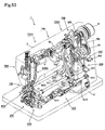
- the single-thread locked handstitch sewing machine of this invention is equipped with a open eye needle 13 which pierces a sewing thread 20 to a fabric workpiece 21 by providing a thread capturing open eye 13a laterally and by performing the linear reciprocating motion vertically, a shuttle hook 200 which forms the stitch by letting the sewing thread 20 intersect by the half-turn normal rotation and by the half-turn reverse rotation, a thread draw out actuator 401 which gives the slack to the sewing thread 20 and tightens the stitch by performing the reciprocating motion like a thread take-up lever, and a feed dog 601 which feeds the fabric workpiece 21 by the elliptical motion or the like in a frame 1 consisting of an arm 2 and a bed 3.
- the single-thread locked handstitch sewing machine of this invention is the sewing machine for forming a handstitch on the front surface of the fabric workpiece 21 and for forming a locked stitch on the back surface of the fabric workpiece 21 by using the single thread 20 which was wound in the shuttle hook 200.
- "winding" means being equipped in the state where it was wound.
- the arm 2 is equipped with a upper shaft 5 and an intermediate shaft 8, and the bed 3 is equipped with a horizontal feed shaft 605, an upper and lower feed shaft 613 and a shuttle hook shaft 201, and as for these, the direction of the shafts are set up in horizontal direction respectively.
- the upper shaft 5 is rotatably set up by an upper shaft former bushing 7 and an upper shaft rear bushing 6 in the arm 2
- the intermediate shaft 8 is rotatably set up by an intermediate shaft front bushing 9 and an intermediate shaft rear bushing 10 in the arm 2, respectively.
- the horizontal feed shaft 605 is rotatably set up by a horizontal feed shaft former bushing 606 and a horizontal feed shaft rear bushing 607 in the arm 2, and the upper and lower feed shaft 613 is rotatably set up by an upper and lower feed shaft former bushing 614 and an upper and lower feed shaft rear bushing 611 in the arm 2, respectively.
- the shuttle hook shaft 201 is fixed to an after-mentioned inner shuttle hook driver 203 of the shuttle hook 200 while it is rotatably set up by a shuttle hook shaft rear bushing 225 and a bushing of an shuttle race body attaching portion 202c (refer to Fig.13 ) in the arm 2.
- a driven pulley 4 is equipped at one end of the upper shaft 5, and the driven pulley 4 is driven by a motor M through a drive belt MB which is an endless belt. And, a needle bar crank 101 of the open eye needle-latch wire drive mechanism 100 for driving the open eye needle 13 is equipped to another end of the upper shaft 5.
- the cloth feed drive mechanism 700 for driving the cloth feed mechanism 600 by letting the elliptical motion perform to the feed dog 601 is connected with the intermediate portion of the upper shaft 5.
- An upper shaft drive pulley 25 for driving the feed quantity setting mechanism 300 of the stitch length-the inter-stitch pitch is equipped to the neighborhood of the driven pulley 4 of the upper shaft 5.
- a shuttle hook drive mechanism 220 for driving the shuttle hook 200 and a thread draw out drive mechanism 400 for driving the thread draw out actuator 401 are connected with the intermediate shaft 8.
- the open eye needle-latch wire drive mechanism 100 has the composition that the following things are possible.
- the open eye needle 13 comes down from the upper dead center, and it pierces to the fabric workpiece 21 which is placed on a throat plate 12, and it slips out from the fabric workpiece 21 from the lower dead center and goes up, and it comes down from the upper dead center during the first stroke which performs the linear reciprocating motion vertically and pierces to the fabric workpiece 21, and it captures the sewing thread 20 by the thread capturing open eye 13a when it goes up from the lower dead center, and it pierces to the fabric workpiece 21 by coming down from the upper dead center during the second stroke, and it releases the fabric workpiece 21 which was captured by the thread capturing open eye 13a when it goes up from the lower dead center.
- the first stroke of the open eye needle 13 means the first stitch that the open eye needle 13 reaches the upper dead center of needle ⁇ the lower dead center of needle ⁇ the upper dead center of needle
- the second stroke of the open eye needle 13 means the second stitch that the open eye needle 13 reaches the upper dead center of needle ⁇ the lower dead center of needle ⁇ the upper dead center of needle.
- this open eye needle 13 is fixed to a needle clamp 107, and the needle clamp 107 is fixed to the lower end portion of a needle bar 11 which was set up at the arm 2 by a needle clamp screw 108 in the state that the reciprocating motion can perform linearly and vertically by a needle bar upper bushing 105 and a needle bar lower bushing 106.
- a needle bar holder 104 is fixed to the needle bar 11 between the needle bar upper bushing 105 and the needle bar lower bushing 106.
- a crank rod pin 104a which is formed in the needle bar holder 104 is rotatably connected with one end of a needle bar crank rod 103, and another end of the needle bar crank rod 103 is rotatably connected with the needle bar crank 101 which is fastened to another end of the upper shaft 5. Therefore, because the needle bar crank rod 103 cranks by the rotation of the upper shaft 5 through the needle bar crank 101, the needle bar 11 that the open eye needle is fixed by the needle clamp 107 performs the linear reciprocating motion vertically by the needle bar holder 104.
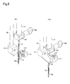
- the thread capturing open eye 13a of the open eye needle 13 is opened and closed by the latch wire 14.
- This latch wire 14 is fixed to a latch wire clamp 111 by a latch wire clamp screw 112, and the latch wire clamp 111 is fixed to the lower end portion of a latch wire bar 15 which was set up in the arm 2 in the state that the linear reciprocating motion can perform vertically by a latch wire bar upper bushing 113 and a latch wire bar lower bushing 114.
- a latch wire bar receiver 116 is fixed to the latch wire bar 15 between the latch wire bar upper bushing 113 and the latch wire bar lower bushing 114.
- a latch wire bar supporting upper arm 118 which was fixed to the needle bar 11 between the needle bar upper bushing 105 and the needle bar holder 104 has a gap to be able to move and is fitted in.
- a latch wire bar rotation stopper 120 is fixed to the latch wire bar 15 between the latch wire bar supporting upper arm 118 and the latch wire bar upper bushing 113, and a latch wire bar guide 121 which was fixed so that it projects to the arm 2 is slidably fitted into a notch 120a which is formed in this latch wire bar rotation stopper 120. Therefore, the latch wire bar 15 that the latch wire bar rotation stopper 120 is fixed does not rotate.
- the latch wire bar rotation stopper 120 is pulled downward always by fixing another end of a latch wire bar spring 119 which is fixed to one end of the arm 2.
- An O-ring 117 is fitted into the latch wire bar 15 in the lower side of the latch wire bar rotation stopper 120 and an O-ring 115 is fitted into the latch wire bar 15 in the upper side of the latch wire bar lower bushing 114.
- the O-ring 117 functions as the buffer material when the latch wire bar rotation stopper 120 abuts on the latch wire bar supporting upper arm 118
- the O-ring 115 functions as the buffer material when the latch wire bar lower bushing 114 abuts on the latch wire bar receiver 116.
- the latch wire bar supporting upper arm 118 lets the latch wire bar rotation stopper 120 go up against the elastic force of the latch wire bar spring 119.
- the latch wire 14 also goes up while the open eye needle 13 goes up, as shown in Fig.5 (A) and Fig.6 (A) , the thread capturing open eye 13a of the open eye needle 13 becomes closed state by the latch wire 14. That is, when the open eye needle 13 goes toward the upper dead center from the lower dead center, the thread capturing open eye 13a is closed by the latch wire 14.
- a presser mechanism 500 for letting the presser foot 501 to press the fabric workpiece 21 to the throat plate 12 operate is equipped.
- the presser mechanism 500 is set up to the arm 2 in the state that a presser bar 503 can perform the linear reciprocating motion vertically, a presser foot leg 502 that the presser foot 501 was swingably assembled at the lower end portion of the presser bar 503 is fixed by a presser stopper screw 509.
- a presser bar pressure adjusting screw 508 is fixed at the upper portion of the presser bar 503, and the presser bar pressure adjusting screw 508 is threadably mounted on the upper portion of the arm 2.
- a presser bar holder 505 is fixed to the presser bar 503, and a presser bar pressure adjusting spring 504 is fitted into the presser bar 503 between the presser bar holder 505 and the lower surface of the arm 2. The suppress strength to the fabric workpiece 21 of the presser foot 501 by this presser bar pressure adjusting spring 504 can be adjusted by turning the presser bar pressure adjusting screw 508.
- a presser upholding lever 506 which engages to the presser bar holder 505 is rotatably equipped to a presser upholding lever shaft 507 which is fixed to the arm 2.
- the presser bar holder 505 goes up when the presser upholding lever 506 goes up, and the presser bar holder 505 comes down when the presser upholding lever 506 comes down. Therefore, the space between the presser foot 501 and the throat plate 12 is made when the presser upholding lever 506 goes up, and the fabric workpiece 21 is pressed to the throat plate 12 when the presser upholding lever 506 comes down after placing the fabric workpiece 21 onto the throat plate 12, thereby, the fabric workpiece 21 can be set onto the throat plate 12.
- the cloth feed mechanism 600 is equipped with the feed dog 601.
- this cloth feedmechanism 600 is equipped to the lower side of the throat plate 12, and the feed dog 601 is fixed to the almost center portion of a feed base 602.
- the one end of the feed base 602 is rotatably connected with a horizontal feed arm 604 which is fixed to another end of the horizontal feed shaft 605 by a horizontal feed arm shaft 603. Therefore, because the horizontal feed arm 604 performs the reciprocating rocking by reciprocating and rotating the horizontal feed shaft 605, the feed dog 601 can perform the reciprocating motion horizontally.
- a upper and lower feed roller shaft 609 is fixed to another end of the feed base 602, and a upper and lower feed roller 608 is rotatably equipped to the upper and lower feed roller shaft 609.
- This upper and lower feed roller 608 is inserted slidably to a forked portion 616a of a feed dog up and down drive fork 616 which is fixed to one end of the upper and lower feed shaft 613. Therefore, because the feed dog up and down drive fork 616 performs the reciprocating rocking by reciprocating and rotating the upper and lower feed shaft 613, the upper and lower feed roller 608 which fits into the feed dog up and down drive fork 616 can let another end of the feed base 602 reciprocate up and down.
- one stitch length P1 of the stitch feed is the stitch length of the handstitch which is formed on the front surface of the fabric workpiece 21, and one inter-stitch pitch P2 of the inter-stitch feed is the space length between the continuous two handstitches.
- the cloth feeddrivemechanism 700 transmits a stitch length feed quantity and a inter-stitch pitch feed quantity which are set up in the feed quantity setting mechanism 300 in each fabric workpiece feed mode respectively, and it feeds the fabric workpiece 21 by the feed dog 601.
- a horizontal feed cam 701 which reciprocates and rotates the horizontal feed shaft 605
- an upper and lower feed cam 717 which is fixed to the upper shaft 5 and which reciprocates and rotates the upper and lower feed shaft 613 are fixed to the upper shaft 5.
- "each fabric workpiece feed mode” means the stitch length feed and the inter-stitch pitch feed.
- the horizontal feed cam 701 is an eccentric cam.
- a horizontal feed drive rod 702 is rotatably fitted into a cam portion 701a, and the one end of a horizontal feed vertical rod 704 is rotatably connected with an end of arm 702a of the horizontal feed drive rod 702 by a linking pin 703.
- Another end of the horizontal feed vertical rod 704 is rotatably connected with a horizontal feed shaft drive arm 705 which is fixed to another portion of the horizontal feed shaft 605 by a linking pin 706. Therefore, because the horizontal feed cam 701 lets the horizontal feed drive rod 702 perform the eccentric motion when the upper shaft 5 rotates, the horizontal feed vertical rod 704 performs the up-and-down motion and the horizontal feed shaft drive arm 705 can let the horizontal feed shaft 605 perform the reciprocating rotation.
- the upper and lower feed cam 717 is the eccentric cam.
- the one end of a feed dog up and down drive vertical rod 714 is rotatably fitted into a cam portion 717a, and another end of the feed dog up and down drive vertical rod 714 is rotatably connected with a feed dog up and down shaft drive arm 715 which is fixed to another portion of the upper and lower feed shaft 613 by a linking pin 716. Therefore, because the horizontal feed cam 701 lets the one end of the feed dog up and down drive vertical rod 714 perform the eccentric motion when the upper shaft 5 rotates, the feed dog up and down drive vertical rod 714 itself performs the up-and-down motion and the feed dog up and down shaft drive arm 715 can let the upper and lower feed shaft 613 perform the reciprocating rotation.
- the horizontal feed arm 604 performs the reciprocating rocking and it lets the feed base 602 reciprocate horizontally.
- the feed dog up and down drive fork 616 performs the reciprocating rocking and the upper and lower feed roller 608 which fits into the feed dog up and down drive fork 616 lets another end of the feed base 602 reciprocate in the upper and lower direction. Therefore, the feed dog 601 which is fixed to the feed base 602 can perform so-called four feed process movements which is rise ⁇ advance ⁇ descend ⁇ retreat.
- the feed quantity setting mechanism 300 sets up a stitch length feed quantity of a stitch length feed and a inter-stitch pitch feed quantity of a inter-stitch pitch feed respectively.
- the feed quantity setting mechanism 300 consists of a reverse T-shaped feed adjuster 310 which is pivotally attached to a supporting arm 311 which is pivotally supported to the intermediate shaft 8 that one-half is decelerated from the upper shaft 5 which drives the open eye needle 13.
- a stitch feed adjusting lever 301 which is a stitch length feed quantity operating member and a inter-stitch feed adjusting lever 302 which is an inter-stitch pitch feed quantity operating member are pivotally attached to both arms which become a horizontal arm of the reverse T-shaped feed adjuster 310.
- an end of arm 311a of the supporting arm 311 is rotatably fitted into the intermediate shaft 8 while it connects with the portion which crosses the horizontal arm and the vertical arm of the reverse T-shaped feed adjuster 310 by a feed adjuster pin 309 rotatably.
- One end of a first adjusting lever link 307 is rotatably connected with one end of horizontal arm 310a of the reverse T-shaped feed adjuster 310 by a linking pin 308A, and the portion which becomes the operating point of the inter-stitch feed adjusting lever 302 is rotatably connected with another end of the first adjusting lever link 307 by a linking pin 308B.
- One end of a second adjusting lever link 307' is rotatably connected with another end of horizontal arm 310b of the reverse T-shaped feed adjuster 310 by a linking pin 308C, and the portion which becomes the operating point of the stitch feed adjusting lever 301 is rotatably connected with another end of the second adjusting lever link 307' by a linking pin 308D.
- the portions which become the fulcrums respectively are rotatably equipped to an adjusting lever shaft 303 which is fixed to the arm 2.
- a vertical arm end 304a of a T-shaped adjusting lever partition plate 304 is equipped to the adjusting lever shaft 303, and it is fixed to the arm 2 by a setscrew 313A and 313B so that one end of the horizontal arm 304b which becomes the horizontal arm is positioned upward and another end of the horizontal arm 304c is positioned downward.
- a partition plate upper spacer 305 is fixed to one end of horizontal arm 304b which becomes the horizontal arm by the setscrew 313A
- a partition plate lower spacer 306 is fixed to another end of horizontal arm 304c by the setscrew 313B.
- the partition plate upper spacer 305 is the limiter of the upward position of the portion which becomes the point of force of the inter-stitch feed adjusting lever 302 and the stitch feed adjusting lever 301
- the partition plate lower spacer 306 is the limiter of the downward position of the portion which becomes the point of force of the inter-stitch feed adjusting lever 302 and the stitch feed adjusting lever 301.
- the inter-stitch feed adjusting lever 302 and the stitch feed adjusting lever 301 are pivotally supported to the adjusting lever shaft 303 that the portion which becomes the fulcrum is firmly fixed to the arm 2, and it is fixed to the position which is set up by the operation of the portion of the point of force which becomes the operating finger grip in the state pressed by the elastic member such as the wavelike washer.
- this fixing state is called semi-fixing.
- a feed mode changeover mechanism 350 which is changed over in sequence to each fabric workpiece feedmode corresponding to the stitch length feed and the inter-stitch pitch feed respectively every one skip stitch set is equipped.
- "skip stitch set” means a set of the handstitch and the locked stitch.
- the feed mode changeover mechanism 350 is equipped with a feed changeover triangular cam 351 which is firmly fixed to the intermediate shaft 8 and has two deviating points and a feed changeover rod 352 which contacts to the outside of the feed changeover triangular cam 351.
- a connecting end 352a of the feed changeover rod 352 is pivotally attached to one end of a stitch length changeover link 355, and another end of the stitch length changeover link 355 is pivotally attached to a vertical arm end 310c of the reverse T-shaped feed adjuster 310.
- the feed changeover triangular cam 351 is in contact with the outside of an almost quadrangular cam hole 352b which is formed in the feed changeover rod 352, and the connecting end 352a of the feed changeover rod 352 is rotatably connected to one end of the stitch length changeover link 355 by a linking pin 354, and another end of the stitch length changeover link 355 is rotatably connected to the vertical arm end 310c of the reverse T-shaped feed adjuster 310 by a linking pin 312.
- the cloth feed drive mechanism 700 is equipped with a horizontal feed connection link 712 whose one end is pivotally attached to the connecting end 352a of the feed changeover rod 352, a horizontal feed connection crank 709 whose first arm 709a is pivotally attached to another end of the horizontal feed connection link 712, and a horizontal feed rod link 707 whose one end is pivotally attached to a second arm 709b of the horizontal feed connection crank 709 and another end is pivotally attached to the horizontal feed vertical rod 704.
- one end of the horizontal feed connection link 712 is rotatably connected with the connecting end 352a of the feed changeover rod 352 by the linking pin 354, and another end of the horizontal feed connection link 712 is rotatably connected with the first arm 709a of the horizontal feed connection crank 709 by a linking pin 711, and the second arm 709b of the horizontal feed connection crank 709 rotatably connects with one end of the horizontal feed rod link 707 by a linking pin 708.
- Another end of the horizontal feed rod link 707 rotatably connects with the horizontal feed vertical rod 704 and an arm end 702a of the horizontal feed drive rod 702 by the linking pin 703.
- an intermediate shaft driven pulley 26 is fixed to one end of the intermediate shaft 8, and a timing belt TB which is the endless belt is wound between this intermediate shaft driven pulley 26 and the upper shaft drive pulley 25 which is fixed to the upper shaft 5.
- a rotational motion is transmitted to the intermediate shaft 8 by decelerating one-half from the upper shaft 5.
- the shuttle hook 200 and the shuttle hook drive mechanism 220 are located under the throat plate 12, and these are the shuttle hooks that the sewing thread 20 is wound and the sewing thread 20 is drawn out of a thread exit 212a.
- These have following mechanism composition. That is, during the first stroke, When the open eye needle 13 comes down from the upper dead center, pierces the fabric workpiece 21 and goes up from the lower dead center, the shuttle hook 200 performs the half-turn reverse rotation, and the sewing thread 20 is tightened by further reverse rotation along with the rising of the open eye needle 13 which captures the sewing thread 20 by the thread capturing open eye 13a.
- the open eye needle 13 when the open eye needle 13 comes down from the upper dead center, pierces the fabric workpiece 21 and goes up from the lower dead center, the open eye needle 13 has a loop-taker point 205a which scoops the captured sewing thread 20 by the thread capturing open eye 13a according to the half-turn normal rotation of the shuttle hook, and the shuttle hook 200 scoops the captured sewing thread 20 by the loop-taker point 205a of the shuttle hook by the rotation of the shuttle hook and releases it from the thread capturing open eye 13a. And the shuttle hook 200 guides the released sewing thread 20 into the shuttle hook by the further rotation of the shuttle hook, thereby the sewing thread 20 can be interlaced to the sewing thread 20 which is wound in the shuttle hook.
- a bobbin case 212 which houses a bobbin 211 that the sewing thread 20 is wound is incorporated in the inner shuttle hook 205, and the bobbin case 212 is rotatably loaded together with the inner shuttle hook 205 in the shuttle racebody 202.
- the "loading" means spanning and equipping.
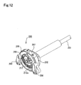
- the shuttle hook 200 is equipped with the bobbin case 212 which houses a bobbin 211 that the sewing thread 20 is wound, the inner shuttle hook 205 which has the loop-taker point 205a along with removably housing the bobbin case 212, and the shuttle race body 202 that the inner shuttle hook is rotatably housed and that the rotation stop is performed to the bed 3.
- the inner shuttle hook 205 has a bobbin case housing 205b which houses the bobbin case 212, and the bobbin case 212 is removably housed in the bobbin case housing 205b.
- the shuttle race body 202 has an inner shuttle hook driver 203 that an inner shuttle hook driver spring 204 is fixed and has an inner shuttle hook housing 202a which houses the inner shuttle hook 205.
- the shuttle race body 202 has a shuttle race body attaching portion 202c that a shuttle hook shaft hole 202b to insert rotatably to one end of the shuttle hook shaft 201 is equipped, and the rotation center of this shuttle hook shaft hole 202b and the inner shuttle hook housing 202a is concentric with the rotation center of the shuttle hook shaft 201.
- the inner shuttle hook driver 203 is housed in the inner shuttle hook housing 202a of the shuttle race body 202 and is fixed to the shuttle hook shaft 201 which is inserted in the shuttle hook shaft hole 202b.
- the inner shuttle hook 205 and an inner shuttle hook holder 206 are housed in the inner shuttle hook housing 202a, and the inner shuttle hook holder 206 is fixed by a right inner shuttle hook holder pawl 208 and a left inner shuttle hook holder pawl 209 in the state that the spring force is given by an inner shuttle hook holder pawl spring 210.
- the predetermined gap exists between the inner shuttle hook 205 and the inner shuttle hook driver 203 in which the inner shuttle hook driver spring 204 is fixed.
- the relation between the inner shuttle hook driver spring 204 of the inner shuttle hook driver 203 and the inner shuttle hook 205 can regulate the free rotation of the inner shuttle hook 205 at both ends of the inner shuttle hook driver spring 204. Therefore, when the inner shuttle hook driver 203 performs the half-turn normal rotation around the shuttle hook shaft 201, one end of the inner shuttle hook driver spring 204 abuts on the inner shuttle hook 205 and another end of the inner shuttle hook driver spring 204 has the gap O 2 between the inner shuttle hook 205 (refer to Fig.18 (O) ).
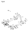
- the shuttle hook drive mechanism 220 consists of a shuttle hook drive triangular cam 230 which is fixed to another end of the intermediate shaft 8 and is the eccentric cam, a shuttle hook drive fork 231 which contacts to the outside of the shuttle hook drive triangular cam 230, a shuttle hook drive vertical rod 228 which is connected with the portion that one end becomes the point of force of the shuttle hook drive fork 231, a shuttle hook drive fan-shaped gear 233 that an arm 233a is connected with another end of the shuttle hook drive vertical rod 228 and is fixed to a fan-shaped gear shaft 221, and a shuttle hook shaft gear 224 which is meshed to the shuttle hook drive fan-shaped gear 233 and is fixed to the shuttle hook shaft 201.
- the shuttle hook drive triangular cam 230 contacts to the outside of an almost square-shaped cam groove 231a which is formed in the shuttle hook drive fork 231, and one end of the shuttle hook drive vertical rod 228 is ratatably connected with the portion which becomes the point of force of the shuttle hook drive fork 231 by a linking pin 229, besides another end of the shuttle hook drive vertical rod 228 is rotatably connected with the arm 233a of the shuttle hook drive fan-shaped gear 233 by a linking pin 227.
- the portion which becomes the fulcrum of the shuttle hook drive fork 231 ispivotally supported by a shuttle hook drive fork shaft 232, and this shuttle hook drive fork shaft 232 is fixed to the arm 2.
- the fan-shaped gear shaft 221 is arranged on the bed 3 so that the axial direction becomes horizontal, and is rotatably set up by a fan-shaped gear shaft former bushing 222 and a fan-shaped gear shaft rear bushing 223.
- the shuttle hook drive mechanism 220 of such a composition when the intermediate shaft 8 rotates, because the shuttle hook drive fork 231 lets the shuttle hook drive vertical rod 228 perform up-and-down motion by making the shuttle hook drive fork shaft 232 the fulcrum by eccentric motion of the shuttle hook drive triangular cam 230, the shuttle hook drive fan-shaped gear 233 performs the reciprocating rocking. Based on this reciprocating rocking of the shuttle hook drive fan-shaped gear 233, because also the shuttle hook shaft 201 that the shuttle hook shaft gear 224 is fixed performs the reciprocating rotating movement with the constant rotating angle, the inner shuttle hook 205 of the shuttle hook 200 can perform the half-turn normal rotation and the half-turn reverse rotation.
- the thread draw out drive mechanism 400 has following mechanism composition. That is, when the thread capturing open eye 13a of the open eye needle 13 captures the sewing thread 20, the thread draw out actuator 401 gives the tension to the sewing thread 20 which is drawn out from the thread exit 212a by rotation of the shuttle hook 200 by abutting circumferentially on the open eye needle 13, and thread draw out actuator 401 can tighten the sewing thread 20 which guides out from the shuttle hook 200.
- "abut circumferentially on” means abutting circumferentially on the certain portion.
- This thread draw out actuator 401 has following function.
- the thread draw out actuator 401 hooks the sewing thread 20 which is drawn out from the thread exit 212a of the shuttle hook 200, and tightens the thread by drawing out the thread from the shuttle hook 200. And after the thread draw out actuator 401 captures the sewing thread 20 by the thread capturing open eye 13a, it releases the sewing thread 20 which is hooked.
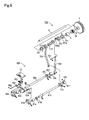
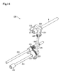
- such the thread draw out drive mechanism 400 is equipped with a screw gear 410 which converts the rotational motion in the horizontal direction of the intermediate shaft 8 into the rotational motion in the vertical direction, a thread draw out actuator drive cam shaft 408 which transmits the rotational motion which is converted from the horizontal direction into the vertical direction by the screw gear 410, and a thread draw out actuator drive cam 407 which gives the rotational motion of the thread draw out actuator drive cam shaft 408 to the above-mentioned function of the thread draw out actuator 401.
- a first gear 410A of the screw gear 410 is fixed to the intermediate shaft 8, and a second gear 410B is fixed to one end (upper end) of the thread draw out actuator drive cam shaft 408.
- the thread draw out actuator drive cam 407 that a cam groove 407a is formed and is a face cam is fixed to another end (lower end) of the thread draw out actuator drive cam shaft 408.
- This thread draw out actuator drive cam shaft 408 is rotatably set up by a thread draw out actuator drive cam shaft upper bushing 411 and a thread draw out actuator drive cam shaft lower bushing 412 which are equipped to a thread draw out actuator drive cam shaft tube 409 which is fixed to the arm 2.
- the thread draw out drive mechanism 400 is equipped with a thread draw out actuator drive rod base 405 that it is arranged horizontally and a cam follower 406 which engages the cam groove 407a of the thread draw out actuator drive cam 407 is rotatably provided by a cam follower pin 413, a thread draw out actuator drive rod 404 that it is arranged horizontally and one end is fixed to the thread draw out actuator drive rod base 405 and another end is rotatably fixed to an arm end 403a of a thread draw out actuator drive arm 403 by a pin 414, and a thread draw out actuator rocking shaft 402 that it is arranged vertically and one end is fixed to the thread draw out actuator drive arm 403 and another end is fixed to the thread draw out actuator 401.
- a hollow elongate hole 405a is formed in the thread draw out actuator drive rod base 405, and the thread draw out actuator drive cam shaft 408 is inserted into this elongate hole 405a.
- the thread draw out actuator drive rod base 405 is movably equipped to the thread draw out actuator drive cam shaft 408 under the thread draw out actuator drive cam 407 horizontally by a thrust collar 415.
- the cam follower 406 lets the thread draw out actuator 401 rock in accordance with the shape of the cam groove 407a of the thread draw out actuator drive cam 407. This rocking motion of the thread draw out actuator 401 is the following movement.
- the thread draw out actuator 401 gives the tension to the sewing thread 20 which is drawn out from the thread exit 212a by rotation of the shuttle hook 200 by abutting circumferentially on the open eye needle 13, and thread draw out actuator 401 tightens the sewing thread 20 which guides out from the shuttle hook 200.
- the thread draw out actuator 401 hooks the sewing thread 20 which is drawn out from the thread exit 212a of the shuttle hook 200, and tightens the thread by drawing out the thread from the shuttle hook 200.
- the thread draw out actuator 401 captures the sewing thread 20 by the thread capturing open eye 13a, it releases the sewing thread 20 which is hooked.
- the handstitch on the front surface and the locked stitch on the back surface of the fabric workpiece 21 are formed as the skip stitch set by cooperation of the open eye needle 13, the shuttle hook 200 and the thread drawing out actuator 401, and the stitch length feed of the fabric workpiece 21 for the handstitch is performed by the feed dog 601 during the first stroke of the open eye needle 13, and the inter-stitch pitch feed of the fabric workpiece 21 for the inter-handstitch is performed by the feed dog 601 during the second stroke of the open eye needle 13.
- the stitch length feed quantity of the stitch length feed and the inter-stitch pitch feed quantity of the inter-stitch pitch feed are set up, and each fabric workpiece feed mode corresponding to the stitch length feed and the inter-stitch pitch feed respectively every one skip stitch set is changed over in sequence, and the set stitch length feed quantity and inter-stitch pitch feed quantity are transmitted to the feed drive mechanism 700 in each fabric workpiece feed mode respectively, and thereby, the fabric workpiece 21 is fed by the feed dog 601.
- "cooperation” means working in cooperation with other portions.
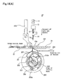
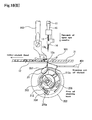
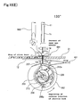
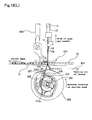
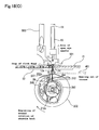
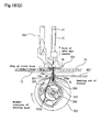
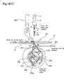
- Fig. 18 (A)-(W) are the movement explanatory view of the open eye needle 13, the shuttle hook 200 and the thread draw out actuator 401
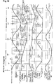
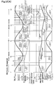
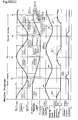
- Fig.19 is the motion diagram of the open eye needle 13, the shuttle hook 200, the thread draw out actuator 401, the latch wire 14 and the feed dog 601.
- Fig. 18 (A) - (W) the drawing of the feed dog 601 is omitted.
- caracoling by reverse rotation of the shuttle hook 200 means the counterclockwise rotation of the inner shuttle hook 205
- caracoling by normal rotation of the shuttle hook 200 means the clockwise rotation of the inner shuttle hook 205.
- the movement explanation is performed from the state that the open eye needle 13 which does not capture the sewing thread 20 by the thread capturing open eye 13a is positioned at the upper dead center and the state that the loop-taker point 205a of the inner shuttle hook 205 is positioned under the vertical direction ( Fig.18 (A) ).
- the shuttle hook 200 is the state of stopping
- the thread draw out actuator 401 is the state which draws out the sewing thread 20 from the bobbin 211 through the thread exit 212a of the bobbin case 212
- the latch wire 14 is the closed state
- the feed dog 601 is the state of the inter-stitch feed.
- the feed direction of the fabric workpiece 21 is the left.
- Fig.19 because the skip stitch set is formed by two rotations of the pulley 4, one cycle of the sewing is shown at 720 degrees in the upper shaft 5, and Fig.18 (A) is the state that the upper shaft 5 is 0 degrees (720 degrees).
- the open eye needle 13 becomes the upper dead center at 0 degrees of the upper shaft 5; the open eye needle 13 becomes the lower dead center at 180 degrees; the open eye needle 13 becomes the upper dead center at 360 degrees; and the open eye needle 13 becomes the lower dead center at 540 degrees.
- the handstitch on the front surface and the locked stitch on the back surface of the fabric workpiece 21 are respectively formed by one sewing thread 20.
- the sewing thread 20 is certainly captured to the thread capturing open eye 13a of the open eye needle 13, and the formation of single-thread locked stitch is performed in the inner space of the sewing machine bed, and the sewing which is suitable to the quasi-handstitch called pinpoint/saddle stitch is possible.
- the handstitch on the front surface and the locked stitch on the back surface of the fabric workpiece 21 are formed respectively and the sewing-work is performed in the state that the handstitch can be seen on the surface for the worker, it is possible to confirm the position of the handstitch, thereby, the accurate sewing can be performed.
- the sewing thread 20 does not come loose easily even if the sewing thread 20 which forms single-thread locked stitch is pulled. Thereby, the firm sewing can be obtained.
- the stitch length and the inter-stitch pitch can be adjusted by the feed quantity setting mechanism 300 and the feed mode changeover mechanism 350.
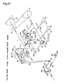
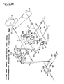
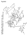
- This movement of the feed quantity setting mechanism 300 and the feed mode changeover mechanism 350 are explained based on Fig.21-Fig.24.
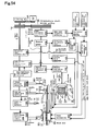
- Fig.21-Fig.24 are the drawings showing the feed quantity setting mechanism 300, the mode changeover mechanism 350, the cloth feed mechanism 600 and the cloth feed drive mechanism 700 schematically.
- the stitch feed adjusting lever 301 and the inter-stitch feed adjusting lever 302 rocks upward and downward respectively.
- the connecting adjusting lever link 307' and 307 move respectively the reverse T-shaped feed adjuster 310 which is supported by the supporting arm 311 to the lower direction in the vertical state. This moved position becomes the lowermost position of the feed adjuster 310.
- the feed changeover rod 352 performs the reciprocating rocking intermittently between the right-and-left two positions q and q' of the almost horizontal direction in the quantity Q of displacement.
- the shape of the feed changeover triangular cam 351 is formed so that the feed changeover rod 352 can stop intermittently in the moved position q and q'.
- the time which stops intermittently in the moved position q and q' is decided by the feed changeover triangular cam 351.
- the feed changeover rod 352 moves to the moved position of q direction by the one rotation of the upper shaft, and moves to the moved position of q' direction by the further one rotation of the upper shaft.
- the point h which is one end of the stitch length changeover link 355 corresponds to the point c' which is another horizontal arm end 310b of the reverse T-shaped feed adjuster 310 which moved to the lowermost position.
- the point h which is one end of the stitch length changeover link 355 corresponds to the point c which is one horizontal arm end 310a of the reverse T-shaped feed adjuster 310 which moved to the lowermost position.
- the setup of each fabric workpiece feed mode can be changed over in sequence. This setup of each fabric workpiece feed mode is performed by the feed changeover rod 352. And the cloth feed is performed every this fabric workpiece feed mode.
- the stitch feed adjusting lever 301 and the inter-stitch feed adjusting lever 302 are respectively set up in the minimum feed pitch
- the first arm 709a of the horizontal feed connection crank 709 is downed to the horizontal feed connection link 712 and rotates clockwise. Therefore, the point j which is the lower end of the second arm 709b of the horizontal feed connection crank 709 rocks to the left direction and is stopping.
- both of the stitch feed adjusting lever 301 and the inter-stitch feed adjusting lever 302 are set up at the lower end points a'd, ad of the maximum feed pitch by operating the stitch feed adjusting lever 301 and the inter-stitch feed adjusting lever 302, because the portions b', b which become each operating points of the stitch feed adjusting lever 301 and the inter-stitch feed adjusting lever 302 respectively are positioned at the uppermost positions, the connecting adjusting lever link 307', 307 respectively move upward the reverse T-shaped feed adjuster 310 which is supported by the supporting arm 311 in the vertical state. This moved position becomes the uppermost position of the feed adjuster 310.
- the feed changeover rod 352 moves to the moved position of q direction by the one rotation of the upper shaft, and moves to the moved position of q' direction by the further one rotation of the upper shaft.
- the point h which is one end of the stitch length changeover link 355 corresponds to the point c' which is another horizontal arm end 310b of the reverse T-shaped feed adjuster 310 which moved to the uppermost position.
- the point h which is one end of the stitch length changeover link 355 corresponds to the point c which is one horizontal arm end 310a of the reverse T-shaped feed adjuster 310 whichmoved to the uppermost position.
- the setup of each fabric workpiece feed mode can be changed over in sequence. This setup of each fabric workpiece feed mode is performed by the feed change over rod 352. And the cloth feed is performed every this fabric workpiece feed mode.
- the stitch feed adjusting lever 301 and the inter-stitch feed adjusting lever 302 are respectively set up in the maximum feed pitch
- the first arm 709a of the horizontal feed connection crank 709 is pushed up to the horizontal feed connection link 712 and rotates clockwise. Therefore, the point j which is the lower end of the second arm 709b of the horizontal feed connection crank 709 rocks to the right direction and is stopping.
- the horizontal feed eccentric cam 701 lets the horizontal feed drive rod 702 performs the reciprocating motion with the quantity e of the eccentricity in the almost horizontal direction.
- the vertical arm end 310c of the reverse T-shaped feed adjuster 310 inclines to the right direction.
- the intermediate shaft 8 rotates clockwise and the feed changeover triangular cam 351 performs the eccentric motion.
- the point h which is one end of the stitch length changeover link 355 corresponds to the point c which is one horizontal arm end 310a of the clockwise rotated reverse T-shaped feed adjuster 310. That is, the point h which is one end of the stitch length changeover link 355 moves to the upper left direction by rotating clockwise on the linking pin 312.
- the horizontal feed connection link 712 which is connected to another end of the stitch length changeover link 355 is pushed up to the upper direction, and the first arm 709a of the horizontal feed connection crank 709 which is connected to this horizontal feed connection link 712 is pushed up and rotates counterclockwise. Therefore, the point j which is the lower end of the second arm 709b of the horizontal feed connection crank 709 rocks to the right direction and is stopping.
- the horizontal feed eccentric cam 701 lets the horizontal feed drive rod 702 perform the reciprocating motion with the quantity e of eccentricity in the almost horizontal direction.
- the vertical arm end 310c of the reverse T-shaped feed adjuster 310 inclines to the right direction.
- the intermediate shaft 8 rotates clockwise and the feed changeover triangular cam 351 performs the eccentric motion.
- the point h which is one end of the stitch length changeover link 355 moves to the lower right direction by rotating counterclockwise on the linking pin 312. Therefore, the horizontal feed connection link 712 which is connected to another end of the stitch length changeover link 355 is pulled down to the lower direction, and the first arm 709a of the horizontal feed connection crank 709 which is connected to this horizontal feed connection link 712 is pulled down and rotates clockwise. Therefore, the point j which is the lower end of the second arm 709b of the horizontal feed connection crank 709 rocks to the left direction and is stopping. In this state, when the upper shaft 5 rotates clockwise, the horizontal feed eccentric cam 701 lets the horizontal feed drive rod 702 perform the reciprocating motion with the quantity e of eccentricity in the almost horizontal direction.
- the point j which is one end of the horizontal feed rod link 707 which is connected to the second arm 709b of the horizontal feed crank 709 becomes the rocking center, and the horizontal feed vertical rod 704 which is connected to another end 1 of the horizontal feed rod link 707 rocks to the right-and-left direction.
- the position that the second arm 709b of the horizontal feed crank 709 rocks to the left direction and stops is set up so that the point j which is one end of the horizontal feed rod link 707 corresponds to the rocking center of the horizontal feed vertical rod 704.
- each setup of each fabric workpiece feed mode can be changed over in sequence.
- the adjusting lever link 307' which is connected to the stitch feed adjusting lever 301 pushes up another horizontal arm end 310b of the reverse T-shaped feed adjuster 310, and the adjusting lever link 307 which is connected to the inter-stitch feed adjusting lever 302 pulls down one horizontal arm end 310a of the reverse T-shaped feed adjuster 310. Consequently, the reverse T-shaped feed adjuster 310 rotates counterclockwise on a pivotally supporting point d which is pivotally supported by the supporting arm 311.
- the vertical arm end 310c of the reverse T-shaped feed adjuster 310 inclines to the left direction.
- the intermediate shaft 8 rotates clockwise and the feed changeover triangular cam 351 performs the eccentric motion.
- the point h which is one end of the stitch length changeover link 355 corresponds to the point c which is one horizontal arm end 310a of the counterclockwise rotated reverse T-shaped feed adjuster 310. That is, the point h which is one end of the stitch length changeover link 355 moves to the lower left direction by rotating clockwise on the linking pin 312.
- the horizontal feed connection link 712 which is connected to another end of the stitch length changeover link 355 is pulled down to the lower direction, and the first arm 709a of the horizontal feed connection crank 709 which is connected to this horizontal feed connection link 712 is pulled down and rotates clockwise. Therefore, the point j which is the lower end of the second arm 709b of the horizontal feed connection crank 709 rocks to the left direction and is stopping. In this state, when the upper shaft 5 rotates clockwise, the horizontal feed eccentric cam 701 lets the horizontal feed drive rod 702 perform the reciprocating motion with the quantity e of eccentricity in the almost horizontal direction.
- the point j which is one end of the horizontal feed rod link 707 which is connected to the second arm 709b of the horizontal feed crank 709 becomes the rocking center, and the horizontal feed vertical rod 704 which is connected to another end 1 of the horizontal feed rod link 707 rocks to the right-and-left direction.
- the position that the second arm 709b of the horizontal feed crank 709 rocks to the left direction and stops is set up so that the point j which is one end of the horizontal feed rod link 707 corresponds to the rocking center of the horizontal feed vertical rod 704.
- the vertical arm end 310c of the reverse T-shaped feed adjuster 310 inclines to the left direction.
- the intermediate shaft 8 rotates clockwise and the feed changeover triangular cam 351 performs the eccentric motion.
- the point h which is one end of the stitch length changeover link 355 moves to the upper right direction by rotating counterclockwise on the linking pin 312. Therefore, the horizontal feed connection link 712 which is connected to another end of the stitch length changeover link 355 is pushed up to the upper direction, and the first arm 709a of the horizontal feed connection crank 709 which is connected to this horizontal feed connection link 712 is pushed up and rotates counterclockwise. Therefore, the point j which is the lower end of the second arm 709b of the horizontal feed connection crank 709 rocks to the right direction and is stopping. In this state, when the upper shaft 5 rotates clockwise, the horizontal feed eccentric cam 701 lets the horizontal feed drive rod 702 perform the reciprocating motion with the quantity e of eccentricity in the almost horizontal direction.
- each setup of each fabric workpiece feed mode can be changed over in sequence.
- the latch wire 14 not to let the sewing thread 20 slip out from the thread capturing open eye 13a is equipped in the open eye needle-latch wire drive mechanism 100 which covers the thread capturing open eye 13a in the period that the open eye needle 13 passes through the throat plate 12 and reaches the upper dead center of the open eye needle 13, and in the period that the open eye needle 13 sticks in the fabric workpiece 21 from the upper dead center of the open eye needle 13.
- the open eye needle-latch wire drive mechanism 130 shown in Fig.25 (A) , (B) and Fig.26 .
- This open eye needle-latch wire drive mechanism 130 is equipped with a latch wire drive link 132, a latch wire bar drive arm 138 and a plate groove cam 135.
- One end of the latch wire drive link 132 is pivotally attached to the needle bar 11 and another end has a roller follower 134.
- the latch wire bar drive arm 138 has a groove 138a in which the roller follower 134 which is fastened to the latch wire bar 15 fits horizontally and movaly.
- a vertical groove 135a and a horizontal groove 135b are formed in the plate groove cam 135.
- the roller follower 134 is fitted into the vertical groove 135a and the horizontal groove 135b.
- the vertical groove 135a lets the roller follower 134 move to the vertical direction toward the lower dead center from the upper dead center of the open eye needle 13.
- the horizontal groove 135b lets the roller follower 134 which moves toward the lower dead center move horizontally at the predetermined position.
- the plate groove cam 135 is fixed to the arm 2.
- One end of the latch wire drive link 132 is rotatably held by the pin 131a which is formed at one end of the needle bar holder 131.
- the crank rod pin 131b is formed at another end of the needle bar holder 131, and one end of the needle bar crank rod 103 is rotatably connected to this crank rod pin 131b.
- This needle bar holder 131 is fixed to the needle bar 11 between the needle bar upper bushing 105 and the needle bar lower bushing 106.
- a roller shaft 133 is formed at another end of the latch wire drive link 132, and the roller follower 134 is composed by holding a roller 134a rotatably.
- the latch wire bar drive arm 138 is fixed to the latch wire bar 15 between the latch wire bar upper bushing 113 and the latch wire bar lower bushing 114. And, the vertical groove 135a and the horizontal groove 135b are connected by the curved groove, and thereby, the plate groove cam 135 is formed in the shape of L.
- the open eye needle-latch wire drive mechanism 130 constituted as described above, in the period that the thread capturing open eye 13a of the open eye needle 13 comes down from the upper dead center and pierces the fabric workpiece and passes through the throat plate 12, and in the period that the thread capturing open eye 13a of the open eye needle 13 goes up from the lower dead center and passes through the throat plate 12 and slips out from the fabric workpiece and reaches the upper dead center, the latch wire 14 which covers the thread capturing open eye 13a can be driven.
- the reason to drive the latch wire 14 by the open eye needle-latch wire drive mechanism 130 is as follows.
- the open eye needle 13 pierces the fabric workpiece, the occurrence of the thread breakage by hooking the thread of the fabric workpiece by the thread capturing open eye 13a is prevented. And, it is prevented that the captured thread slips out from the thread capturing open eye 13a.
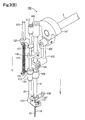
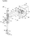
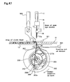
- the thread shifting mechanism 800A and 800B which shift the sewing thread captured by the thread capturing open eye 13a between the needlepoint of the open eye needle 13 and the fabric workpiece.
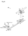
- the thread shifting mechanism 800A is equipped with a thread shifter 801 which is formed in the L-shape to hook the thread slack which occurs between the needlepoint of the open eye needle 13 and the fabric workpiece 21, an elliptical drive mechanism 802 which is attached to the upper shaft 5 and has the elliptical motion trace in the horizontal plain surface and a link mechanism 803 which transmits the elliptical motion by the elliptical drive mechanism 802 to the thread shifter 801.
- the elliptical drive mechanism 802 consists of a column-shaped thread shifting drive cam 804 that a cam groove 804a is fixed to the upper shaft 5 in the eccentric state and is formed around the circumference, a cylindrical thread shifting drive member 805 which is fitted into so as to cover the thread shifting drive cam 804 and that a thread shifting drive arm 805a that the link mechanism 803 is connected is formed, and a cam follower 806 which is mounted on the cylindrical thread shifting drive member 805 and is fitted into the cam groove 804a of the thread shifting drive cam 804.
- the cam groove 804a of the thread shifting drive cam 804 is formed so that the thread shifting drive member 805 is able to perform the linear reciprocating motion in the same direction of the axial direction of the upper shaft 5.
- the cam follower 806 consists of a roller shaft 806a which is fixed to the aforementioned thread shifting drive member 805 so as to protrude partly from the inner wall of the thread shifting drive member 805 and a roller 806b which is rotatably held at the tip of the roller shaft 806a and fits into the cam groove 804a of the thread shifting drive cam 804.
- the link mechanism 803 consists of a thread shifting drive arm shaft 807 which is rotatably held in a shaft hole 805a' which is equipped at the thread shifting drive arm 805a of the thread shifting drive member 805, a thread shifting adjusting shaft 808 whose one end is connected so as to bend freely to the tip of the thread shifting drive arm shaft 807, a thread shifting attachment shaft 809 that a female screw 809a into which a male screw 808a which is equipped to another end of the thread shifting adjusting shaft 808 is screwed is equipped to one end and the thread shifter 801 is fixed to another end, and a thread shifting attachment shaft holder 810 that a male screw 810a which is screwed into a female screw (not shown in the drawing) which is equipped to the predetermined position of the arm 2 is equipped and rotatably supports the thread shifting attachment shaft 809.
- the thread shifting adjusting shaft 808 and the thread shifting attachment shaft 809 become rotatable.
- the female screw which is equipped to the predetermined position of the arm 2 and the male screw 810a of the thread shifting attachment shaft holder 810 are screwed without being tightened completely, the thread shifting attachment shaft holder 810 becomes rotatable for the arm 2.
- the tip portion 801a of the thread shifter 801 turns around one time on the presser foot 501 by the elliptical motion of the motion trace 830 while the upper shaft 5 turns around one time. Therefore, the tip portion 801a of the thread shifter 801 can perform the elliptical motion without interference to the open eye needle 13 which performs the linear motion in the up-and-down direction.
- the thread shifting drive member 805 having the cam follower 806 which engages to the cam groove 804a of the thread shifting drive cam 804 performs the linear reciprocating motion in the same direction as the axial direction of the upper shaft 5, and performs the reciprocating motion in the eccentric direction (hereinafter called "eccentric reciprocating motion") of the thread shifting drive cam 804.
- the tip portion 801a of the thread shifter 801 can perform the elliptical motion of the motion trace 830 as shown in Fig.29 in the horizontal plain surface.
- the open eye needle 13 comes down from the upper dead center in the second stroke, it is possible to shift the thread by scooping the sewing thread which is captured by the thread capturing open eye 13a by the tip portion 801a of the thread shifter 801 between the needle point of the open eye needle 13 and the fabric workpiece.
- the thread shifting mechanism 800B is equipped with a thread shifter 811 which is formed in the L-shape to hook the thread slack which occurs between the needlepoint of the open eye needle 13 and the fabric workpiece 21, an eccentric mechanism 812 which converts the rotational motion of the upper shaft 5 to the eccentric motion, a first link mechanism 813 which is connected to the eccentric mechanism 812 and converts the eccentric motion of the aforementioned eccentric mechanism to the horizontal motion, a second link mechanism 814 which is connected to the eccentric mechanism 812 and converts the eccentric motion of the aforementioned eccentric mechanism to the up-and-down motion and a thread shifting attachment arm 815 which is connected to the first link mechanism 813 and the second link mechanism 814 and converts the motion trace to the elliptical motion in the horizontal direction by combining the horizontal motion of the first link mechanism 813 and the up-and-down motion of the second link mechanism 814 and transmits the elliptical motion to the thread shifter 801.
- a thread shifter 811 which is formed in the L-shape to
- the eccentric mechanism 812 uses a thread shifting drive eccentric shaft 816 instead of a crank rod pin 102 which connects the needle bar crank rod 103 of the open eye needle-latch wire drive mechanism 100 which is shown in above-mentioned Fig.3 (A) , (B) and Fig. 4 to the needle bar crank 101.
- the thread shifting drive eccentric shaft 816 consists of a crank rod pin 816a which connects the needle bar crank rod 103 to the needle bar crank 101 and an arm portion 816b that the crank rod pin 816a is fixed to one end and an eccentric shaft 816c is fixed to another end.
- the first link mechanism 813 is equipped with a thread shifting horizontal rocking arm 817 that an elongate hole 817a which engages to the eccentric shaft 816c of the thread shifting drive eccentric shaft 816 is formed in one end.
- the elongate hole 817a is formed in the thread shifting horizontal rocking arm 817 so that the longer direction becomes up-and-down direction.
- This thread shifting horizontal rocking arm 817 is constituted so that the elongate hole 817a which is one end becomes the point of force, and so that another end becomes the operating point, and so that the portion between one end and another endbecomes the fulcrum.
- a thread shif tingmechanism attachment board 818 which supports the fulcrum of the thread shifting horizontal rocking arm 817 is fixed to the arm 2.
- the portion which becomes the fulcrum of the thread shifting horizontal rocking arm 817 is rotatably supported to a thread shifting spindle 819 which is equipped to the predetermined position of the thread shifting mechanism attachment board 818. Therefore, another end of the thread shifting horizontal rocking arm 817 can perform the reciprocating rocking in the horizontal direction whose direction is same as the direction of motion of the feed of the feed dog 601 by making the thread shifting spindle 819 the fulcrum.
- the second link mechanism 814 is equipped with a thread shifting up-and-down drive arm 820 that an elongate hole 820a which engages to the eccentric shaft 816c of the thread shifting drive eccentric shaft 816 is formed in one end.
- the elongate hole 820a is formed in the thread shifting up-and-down drive arm 820 so that the longer direction becomes almost horizontal direction.
- This thread shifting up-and-down drive arm 820 is constituted so that the elongate hole 820a which is one end becomes the point of force, and so that another end becomes the operating point, and so that the portion between one end and another end becomes the fulcrum.
- the fulcrum of the thread shifting up-and-down drive arm 820 is rotatably connected to one end of the thread shifting horizontal rocking arm 817 by a connecting member 821 such as the linking pin.
- a connecting member 821 such as the linking pin.
- an upper end 822a of a thread shifting up-and-down rocking arm 822 which is arranged in the up-and-down direction is rotatably connected to the operating point of the thread shifting up-and-down drive arm 820 by a connecting member 823 such as the linking pin.
- the thread shifting up-and-down drive arm 820 can perform the reciprocating rocking in the up-and-down direction by making the connecting member 821 the fulcrum, the thread shifting up-and-down rocking arm 822 which is connected to another end of the thread shifting up-and-down drive arm 820 can perform the reciprocating motion in the up-and-down direction.
- the arrangement direction of the T-shaped horizontal arm is perpendicular to the direction of motion of the feed of the feed dog 601.
- one horizontal arm end 815a is rotatably connected to another end of the thread shifting horizontal rocking arm 817 by a connecting member 824 such as the linking pin
- a lower end 822b of the thread shifting up-and-down rocking arm 822 is rotatably connected to another horizontal arm end 815b by a connecting member 825 such as the linking pin.
- the arrangement direction of the vertical arm of the thread shifting attachment arm 815 is the vertical direction
- the thread shifter 811 is fixed to a tip 815c.
- a tip portion 811a of the thread shifter 811 turns around one time on the presser foot 501 by the elliptical motion of the motion trace 830 while the upper shaft 5 turns around one time. Therefore, the tip portion 811a of the thread shifter 811 can perform the elliptical motion without interference to the open eye needle 13 which moves linearly in the up-and-down direction.
- eccentric shaft 816c of the thread shifting drive eccentric shaft 816 performs the circular motion
- another end of the thread shifting horizontal rocking arm 817 can perform the reciprocating rocking by the elongate hole 817a in the horizontal direction whose direction is same as the direction of motion of the feed of the feed dog 601 by making the thread shifting spindle 819 the fulcrum
- a vertical arm end 815c of the thread shifting attachment arm 815 which is connected to another end of the aforementioned thread shifting horizontal rocking arm 817 also performs the reciprocating rocking in the horizontal direction whose direction is same as the direction of motion of the feed of the feed dog 601.
- the eccentric shaft 816c of the thread shifting drive eccentric shaft 816 performs the circular motion
- another end of the thread shifting up-and-down drive arm 820 performs the reciprocating rocking by the elongate hole 820a in the up-and-down direction by making the linking pin 821 the fulcrum
- the thread shifting up-and-down rocking arm 822 which is connected to another end of the thread shifting up-and-down drive arm 820 performs the reciprocating motion in the up-and-down direction.
- the tipportion 811a of the thread shifter 811 can perform the elliptical motion of the motion trace 830 as shown in Fig.29 in the horizontal direction.
- the open eye needle 13 comes down from the upper dead center in the second stroke, it is possible to shift the thread by scooping the sewing thread which is captured by the thread capturing open eye 13a by the tip portion 811a of the thread shifter 811 between the needle point of the open eye needle 13 and the fabric workpiece.
- a needle guard 242 in order to correct the irregular motion which occurs by piercing the fabric workpiece by the open eye needle 13 to the needle dropping position in an inner shuttle hook driver 241 to drive the inner shuttle hook 205 by the half-turn normal rotation and the half-turn reverse rotation after the open eye needle 13 pierced the fabric workpiece.
- This inner shuttle hook driver 241 and the needle guard 242 can be used by being exchanged from the inner shuttle hook driver 203 in the above-mentioned shuttle hook 200.
- the inner shuttle hook driver 241 that the needle guard 242 is provided is equipped with a curved needle guard arm 241a which is positioned at the needle dropping position of the open eye needle 13 when the open eye needle 13 pierces the fabric workpiece in the second stroke. And, for preventing the collision to the loop-taker point 205a when the open eye needle 13 bends to the direction of the loop-taker point of the shuttle hook 200, the chamfering 241b is given at the side of the needle dropping position of the aforementioned needle guard arm 241a.
- the chamfering 241a is given to also the needle guard 242 at the side of the needle dropping position of the open eye needle 13, and the generating of the stitch skip by the bend of the open eye needle 13 to the direction away from the loop-taker point of the shuttle hook 200 is prevented.
- the thread draw out actuator 401 which gives the slack to the sewing thread 20 or tightens the stitches by performing the reciprocating motion like the thread take-up lever is equipped. And, even if the stitch length is changed by the feed quantity setting mechanism 300, a thread tightness quantity by the thread draw out actuator 401 becomes constant anytime. Therefore, as shown in Fig. 32 and Fig. 33 , it is preferable to provide the thread tightness adjusting mechanism 420 which adjusts the thread tightness quantity depending on the stitch length which is set by the feed quantity setting mechanism 300.
- thread draw out actuator drive rod 404 which is the component of the thread draw out drive mechanism 400
- one end of a thread draw out actuator drive rod 423 is fixed to the thread draw out actuator drive rod base 405, and another end of this thread draw out actuator drive rod 423 is connected to the arm end 403a of the thread draw out actuator drive arm 403 by a thread draw out actuator adjusting rod 424.
- another end of the thread draw out actuator drive rod 423 and one end of the thread draw out actuator adjusting rod 424 are rotatably connected by a connecting square piece shaft 422, and another end of the thread draw out actuator adjusting rod 424 and the arm end 403a of the thread draw out actuator drive arm 403 are rotatably connected by the pin 414.
- a square piece 421 which is formed in the almost rectangular solid that the longer direction becomes horizontal direction is rotatably fitted into the connecting square piece shaft 422, and the square piece 421 is positioned at the upper direction of the thread draw out actuator drive rod 423.
- the connecting square piece shaft 422 is formed so that the shaft protrudes from both sides by making the flange the center, and thereby, the square piece 421 and the thread draw out actuator drive rod 423 can be separated.
- the square piece 421 is slidably fitted into a groove 425a which is formed at the lower surface of a thread draw out actuator adjusting grooved block 425 which is formed in the almost rectangular solid that the longer direction becomes horizontal direction. This groove 425a is also formed along the longer direction.
- a horizontal arm 426a of a T-shaped thread draw out actuator adjusting plate 426 is fixed to the upper surface of the thread draw out actuator adjusting grooved block 425.
- the thread draw out actuator adjusting grooved block 425 to which the thread draw out actuator adjusting plate 426 is fixed is rotatably fitted into a thread draw out actuator adjusting grooved block shaft 427 which is arranged and fixed by a thrust collar 429 in the up-and-down direction to a thread draw out actuator adjusting board plate 428 which is fixed to the predetermined position of the bed 3.
- the thread draw out actuator adjusting grooved block shaft 427 is inserted in a hole 425b of the thread draw out actuator adjusting grooved block 425 by piercing a hole 426c of the thread draw out actuator adjusting plate 426 and fixed, and is rotatably fitted into the thread draw out actuator adjusting board plate 428 without jolting in the up-and-down direction. Because the thread draw out actuator adjusting grooved block 425 is in the state put on the square piece 421, it does not secede from the thread draw out actuator adjusting grooved block shaft 427.
- a vertical arm end 426b of the thread draw out actuator adjusting plate 426 and the stitch feed adjusting lever 301 are connected by an adjusting wire 431.
- this adjusting wire 431 is inserted into a wire guard 430, and a wire terminal 432 is fixed to the both ends of the adjusting wire 431.
- One wire terminal 432 is fixed to the vertical arm end 426b of the thread draw out actuator adjusting plate 426, and another wire terminal 432 is fixed between the portion which becomes the point of force and the portion which becomes the fulcrum of the stitch feed adjusting lever 301.
- wire terminal 432 of the adjusting wire 431 is movably fixed to the thread draw out actuator adjusting board plate 428 by a wire guide stopper 433, and in another side of the wire terminal 432, the wire guide stopper 433 is movably fixed to the arm 2 by a mounting plate 434.
- a feed adjusting lever knob 323 is fixed to the portion which becomes the point of force of the stitch feed adjusting lever 301.
- FIG.34 (A) is the drawing which is looking from the underneath of the sewing machine. And, the drawing which is positioned at upper side shows the case that tightens the stitch by the thread tightness adjusting mechanism 420, and the drawing which is positioned at lower side shows the case that gives the slack to the stitch respectively.
- Fig.34 (B) is the drawing which is looking from the underneath of the sewing machine.
- the point a is the rotational center of the thread draw out actuator drive cam 407
- the point b is the rotational center of the cam follower 406
- the point c is the rotational center of the thread draw out actuator adjusting grooved block 425
- the point d is the center point of the connecting square piece shaft 422 which connects the thread draw out actuator drive rod 423 and the thread draw out actuator adjusting rod 424
- the point e is the connecting center point which connects the thread draw out actuator adjusting rod 424 and the thread draw out actuator drive arm 403
- the point f is the rotational center point of the thread draw out actuator drive arm 403.
- the L1 which is shown in Fig.34 (B) is the length till the point d from the point a.
- this length is the length that the length till the fixing from the cam follower 406 of the thread draw out actuator drive rod base 405 from the maximum diameter CamRl of the cam groove 407a, the length from the fixing of the thread draw out actuator drive rod 423 and the length of the thread draw out actuator adjusting rod 424 are added.
- the thread draw out actuator adjusting grooved block 425 rotates clockwise by making the thread draw out actuator adjusting grooved block shaft 427 the rotational center, in Fig.34 (A) and (B) , and it is possible to adjust the longer direction to the same direction of the longer direction of the thread draw out actuator drive rod 423.
- the intermediate shaft 8 Fig. 32 , Fig.
- the arm end 403a of the thread draw out actuator drive arm 403 can be rocked with the length L1
- the rocking width becomes the maximum Pa, and the stitch can be tightened.
- the thread draw out actuator drive rod 423 and the square piece 421 which is equipped to the thread draw out actuator adjusting rod 424 by the connecting square piece shaft 422 perform the linear reciprocating motion in the inclined direction in the inside of the groove 425a of the thread draw out actuator adjusting grooved block 425.
- the rotating operation/linear feed changeover mechanism 540 to release the pressing force of the presser foot 501 which performs the pressing force of the fabric workpiece on the throat plate 12 and to perform the rotating operation of the feed direction of the fabric workpiece by hand by making the open eye needle 13 the rotating shaft before the open eye needle 13 comes down from the upper dead center, pierces the fabric workpiece, goes up from the lower dead center and slips out from the fabric workpiece.
- these rotating operation feed is called "free curve sewing". In the free curve sewing, because the sewing worker can operate the feed direction of the fabric workpiece in any direction, the small turned curve sewing of the constant stitch length and the constant inter-stitch pitch can be performed easily.
- the rotating operation/linear feed changeover mechanism 540 has a pressing force release mechanism 520 which transmits the rotational motion of the upper shaft 5 to the presser mechanism 500. And, before the open eye needle 13 comes down from the upper dead center, pierces the fabric workpiece, goes up from the lower dead center and slips out from the fabric workpiece, the pressing force release mechanism 520 can release the pressing force of the presser foot 501 which performs the pressing force of the fabric workpiece on the throat plate 12, and can perform the rotating operation by hand by making the open eye needle 13 the rotating shaft.
- a pressing force release cam drive board 530 is fixed to another end of the upper shaft 5, and a pressing force release cam 528 is fitted into the upper shaft 5 so that it can slide on the upper shaft 5 in the side surface (left side in the drawing) of the pressing force release cam drive board 530.
- the pressing force release cam 528 is the plane cam.
- the pressing force release cam 528 consists of a main body 528b comprising a pulley-like shape that concave portion 528a is formed on the circumference of circle, a circular arc cam portion 528c which is formed in the oval form like the Polydyne curve in one side surface (left side in the drawing) of the main body 528b and a cylindrical portion 528d which is equipped to the side surface (left side in the drawing) of the circular arc cam portion 528c and becomes the same concentricity with the rotational center of the main body 528b. Because the radius of the circular arm of the minimum diameter of the circular arc cam portion 528c and the radius of the cylindrical portion 528d are same, it becomes same plane in that portion.
- a pin hole 528e which can transmit the rotational motion of the upper shaft 5 by slidably fitting in a pin 529 which is fixed in the protruded state to the side surface (left side in the drawing) of the pressing force release cam drive board 530 which is fixed to the upper shaft 5 is formed so that this pressing force release cam 528 does not rotate on the upper shaft 5.
- a pressing force release plate 522 is movably fitted into the presser bar 503 between the presser bar holder 505 of the presser mechanism 500 and the presser foot leg 502.
- a pressing force release spring 521 is fitted into the presser bar 503 between the pressing force release plate 522 and the presser bar holder 505, and the elastic force can be given so as to let the pressing force release plate 522 move to the lower direction.
- a release shaft 526 for transmitting the rotational motion of the upper shaft 5 to the presser mechanism 500 is arranged to the arm 2 so that the shaft direction becomes horizontal. This release shaft 526 is rotatably arranged to the arm 2 by a shaft bushing 525.
- the arm for pressing force release cam 527 which contacts to the circular arc cam portion 528c and the cylindrical portion 528d of the pressing force release cam 528 respectively is fixed to one end of the release shaft 526 and a pressing force release arm 523 is fixed to another end.
- An arm end 523a of the pressing force release arm 523 is swingably connected to the pressing force release plate 522 by the connecting member such as a shoulder screw.
- the rotating operation/linear feed changeover mechanism 540 is equipped with a changeover lever 542 to change over the linear feed and the rotating operation feed by hand, a changeover pin 546 which fits into the concave portion 528a of the pressing force release cam 528 and interlocks with the changeover operation of the changeover lever 542, and a changeover base 541 that the changeover lever 542 and the changeover pin 546 are arranged and which is fixed to the arm 2.
- the changeover base 541 is formed with the inverted-U-shape. Two face-to-face plate surfaces are fixed to the arm 2, and a hole 541a and two circular arced elongate holes 541b, 541c which are arranged around the hole 541a are equipped at a plate surface which is positioned vertically. And, a switching lever 545 is swingably connected by the connecting member such as the shoulder screw at one end 545a in the upper portion of the hole 541a of the plate surface which becomes the opposite side in regard to the side that the upper shaft 5 is arranged.
- the changeover pin 546 is fixed to another end 545b of the switching lever 545 and it is constituted so that it is inserted to the elongate hole 541b.
- the range of rocking is limited to the length of the longer direction of the elongate hole 541b by rocking of the switching lever 545.
- An elongate hole 545c is equipped between one end 545a and another end 545b of this switching lever 545, and a changeover shaft bushing 544 which is fixed to the changeover base 541 is inserted to this elongate hole 545c in the state that it is inserted to the hole 541a.
- a changeover shaft 543 that the changeover lever 542 is fixed to one end and that two arms 543a, 543b are formed at another ends is rotatably inserted to the changeover shaft bushing 544.
- the changeover lever 542 is arranged to the direction that the switching lever 545 of the changeover base 541 is equipped.
- One arm 543a of the changeover shaft 543 is swingably inserted to the elongate hole 541c of the changeover base 541.
- the range of rocking is limited to the length of the longer direction of the elongate hole 541c by rotation of the changeover shaft 543.
- a spring stud 549 is fixed to another arm 543b of the changeover shaft 543.
- One end of a changeover spring 548 is hooked and stopped to the spring stud 549, and another end of the changeover spring 548 is hooked and stopped to the changeover pin 546.
- This changeover spring 548 always gives the elastic force so that the spring stud 549 and the changeover pin 546 come close.
- the pressing force release plate 522 which is connected to the arm end 523a can let the presser foot 501 perform the up-and-down motion by the elastic force of the pressing force release spring 521 ( Fig. 37 (B) and (C) ). Therefore, before the open eye needle 13 comes down from the upper dead center, pierces the fabric workpiece, goes up from the lower dead center and slips out from the fabric workpiece, the pressing force of the presser foot 501 which performs the pressing force of the fabric workpiece on the throat plate 12 can be released.
- the presser bar holder 505 goes up and can release the pressing force of the presser foot 501 which is fixed to the presser bar 503. Therefore, when the presser bar pressure regulating screw 508 is slacked, because the elastic force of the presser bar pressure regulating spring 504 weakens, the rising height of the presser foot 501 can be made high.
- the presser foot 501 can keep the state of the pressing force ( Fig.37 (A) ).
- the stitch length feed for the handstitch of the fabric workpiece is performed by the feed dog 601 and the presser foot 501 in the first stroke of the open eye needle 13
- the inter-stitch pitch feed for the inter-handstitch of the fabric workpiece is performed by the feed dog 601 and the presser foot 501 in the second stroke of the open eye needle 13.
- a hand feed/linear feed changeover mechanism 740 to perform the hand feed of the fabric workpiece while giving the stitch length feed quantity and the inter-stitch pitch feed quantity arbitrarily by releasing the pressing force of the presser foot 501 and by evacuating the feed dog 601 which feeds the fabric workpiece.
- the hand feed like this is called "free motion sewing". In the free motion sewing, because the sewing worker can operate the feed direction of the fabric workpiece to the arbitrary direction, the small turned curve sewing can be performed easily while changing the stitch length and the inter-stitch pitch arbitrarily.
- the hand feed/linear feed changeover mechanism 740 is equipped with a pressing force release mechanism 720A to perform the hand feed of the fabric workpiece while giving the stitch length feed quantity and the inter-stitch pitch feed quantity arbitrarily by releasing the pressing force of the presser foot 501 when the rotational motion of the upper shaft 5 transmits to the presser mechanism 500 and the cloth feed mechanism 600 and when the open eye needle 13 is slipping out from the fabric workpiece.
- the hand feed-linear feed changeover mechanism 740 is equipped with a feed dog evacuate mechanism 720B to perform the hand feed of the fabric workpiece while giving the stitch length feed quantity and the inter-stitch pitch feed quantity arbitrarily by evacuating the feed dog 601 which feeds the fabric workpiece when the open eye needle 13 is slipping out from the fabric workpiece.
- a pressing force release cam drive board 730 is fixed to another end of the upper shaft 5, and a pressing force release cam 728 is fitted into the upper shaft 5 slidably on the upper shaft 5 in the side surface of the pressing force release cam drive board 730.
- the pressing force release cam 728 is the eccentric cam.
- the pressing force release cam 728 consists of a main body 728b comprising a pulley-like shape that concave portion 728a is formed in the inside of the circumferential plane, a cylindrical cam portion 728c which is equipped to one side surface (left side in the drawing) of the main body 728b and which has the rotational center which is positioned at the eccentric position from the rotational center of the main body 728b, and a cylindrical portion 728d which is equipped to the side surface (left side in the drawing) of the camportion 728c and which has the same concentricity with the rotational center of the main body 728b and has the small diameter than the cam portion 728c.
- the cam portion 728c and the cylindrical portion 728d have a place becoming the same plane.
- a pin hole 728e which can slidably fit in a pin 729 which is fixed in the protruded state to the side surface (left side in the drawing) of the pressing force release cam drive board 730 is formed so that this pressing force release cam 728 does not rotate on the upper shaft 5.
- a pressing force release plate 522 is movably fitted into the presser bar 503 between the presser bar holder 505 of the presser mechanism 500 and the presser foot leg 502.
- a pressing force release spring 521 is fitted into the presser bar 503 between the pressing force release plate 522 and the presser bar holder 505, and the elastic force can be given so as to let the pressing force release plate 522 move to the lower direction.
- a release shaft 526 for transmitting the rotational motion of the upper shaft 5 to the presser mechanism 500 is arranged to the arm 2 so that the shaft direction becomes horizontal. This release shaft 526 is rotatably arranged to the arm 2 by a shaft bushing 525.
- a fork for pressing force release 731 which contacts to the cam portion 728c and the cylindrical portion 728d of the pressing force release cam 728 respectively is fixed to one end of the release shaft 526 and a pressing force release arm 523 is fixed to another end.
- an upper arm 731a and a lower arm 731b are movably fitted into the cam portion 728c in the state almost abutted, and the fork for pressing force release 731 is formed so that the space is made between the fork for pressing force release 731 and the cylindrical portion 728d.
- an arm end 523a of the pressing force release arm 523 is swingably connected to the pressing force release plate 522 by the connecting member such as a screw.
- the hand feed/linear feed changeover mechanism 740 is equipped with a changeover lever 742 to change over the linear feed and the hand feed, a changeover pin 746 which fits into the concave portion 728a of the pressing force release cam 728 and interlocks with the changeover operation of the changeover lever 742, and a changeover base 741 that the changeover lever 742 and the changeover pin 746 are arranged and which is fixed to the arm 2.
- the changeover base 741 is formed with the inverted-U-shape. Two face-to-face plate surfaces are fixed to the arm 2, and a hole 741a and two circular arced elongate holes 741b, 741c which are arranged around the hole 741a are equipped to a left side of a plate surface which is positioned vertically. And, a switching lever 745 is swingably connected by the connecting member such as the shoulder screw at one end 745a in the upper portion of the hole 741a of the plate surface which becomes the front face of the sewing machine. The changeover pin 746 is fixed to another end 745b of the switching lever 745 and it is constituted so that it is inserted to the elongate hole 741b.
- the range of rocking is limited to the length of the longer direction of the elongate hole 741b by rocking of the switching lever 745.
- An elongate hole 745c is equipped between one end 745a and another end 745b of this switching lever 545, and a changeover shaft bushing 744 which is fixed to the changeover base 741 is inserted to this elongate hole 745c in the state that it is inserted to the hole 741a.
- a changeover shaft 743 that the changeover lever 742 is fixed to one end and that two arms 743a, 743b are formed at another ends is rotatably inserted to the changeover shaft bushing 744.
- the changeover lever 742 is arranged to the front face side of the sewingmachine that the switching lever 745 of the changeover base 741 is equipped.
- One arm 743a of the changeover shaft 743 is swingably inserted to the elongate hole 741c of the changeover base 741.
- the range of rocking is limited to the length of the longer direction of the elongate hole 741c by rotation of the changeover shaft 743.
- a spring stud 749 is fixed to another arm 743b of the changeover shaft 743.
- One end of a changeover spring 748 is hooked and stopped to the spring stud 749, and another end of the changeover spring 748 is hooked and stopped to the changeover pin 746.
- This changeover spring 748 always gives the elastic force so that the spring stud 749 and the changeover pin 746 come close.
- a feed dog evacuate cam drive board 723 is fixed to the upper shaft 5 that the only predetermined length is away from a pressing force release cam drive board 730, and a feed dog evacuate cam 721 is fitted into the upper shaft 5 slidably on the upper shaft 5 in the side surface (right side in the drawing) of the feed dog evacuate cam drive board 723.
- the feed dog evacuate cam 721 is the eccentric cam.
- the feed dog evacuate cam 721 consists of a main body 721b comprising a pulley-like shape that concave portion 721a is formed on the circumferential plane, a cylindrical cam portion 721c which is equipped to one side surface (right side in the drawing) of the main body 721b and which has the rotational center which is positioned at the eccentric position from the rotational center of the main body 721b, and a cylindrical portion 721d which is equipped to the side surface (right side in the drawing) of the cam portion 721c and which has the same concentricity with the rotational center of the main body 721b and has the small diameter than the cam portion 721c.
- a pin hole 721e which can slidably fit in a pin 722 which is fixed in the protruded state to the side surface (right side in the drawing) of the feed dog evacuate cam drive board 723 is formed so that this feed dog evacuate cam 721 rotates with the upper shaft 5 integrally to the shaft direction of the upper shaft 5 slidably.
- a feed dog up and down drive vertical rod 726 is used instead of the feed dog up and down drive vertical rod 714 of the cloth feed drive mechanism 700.
- a rectangular hole 726a is formed at one end of this feed dog up and down drive vertical rod 726, and the cam portion 721c of the feed dog evacuate cam 721 is movably fitted into the one end of this feed dog up and down drive vertical rod 726 in the state almost abutted for the narrow side.
- a elongate hole 726b is formed at the upper portion, and a vertical rod guide holder 724 which is fixed to the arm 2 is connected by a vertical rod guide pin 725.
- This feed dog up and down drive vertical rod 726 is rotatably connected to the feed dog up and down shaft drive arm 715 which is fixed to another end of the upper and lower feed shaft 613 by the linking pin 716. Therefore, when the upper shaft 5 rotates, because the cam portion 721c of the feed dog evacuate cam 721 lets one end of the feed dog up and down drive vertical rod 726 perform the up-and-down motion, the feed dog up and down shaft drive arm 715 can let the upper and lower feed shaft 613 perform the reciprocating rotation.
- a feed dog evacuate spring 727 which is the helical torsion spring is fitted into the upper and lower feed shaft 613.
- one arm 727a is fixed to the bed 3 and another arm 727b is hooked to the linking pin 716 which connects another end of the feed dog up and down drive vertical rod 726 and the feed dog up and down shaft drive arm 715, and the elastic force is given so as to push the linking pin 716 always to the lower direction.
- the feed dog up and down drive vertical rod 726 stops in the state of lowering and the feed dog 601 can be stopped at the position that it evacuates.
- one hole 741d is equipped to the right side of the plate surface which is positioned at the vertical direction of a changeover base 741.
- a switching lever 750 is swingably connected by the connecting member such as the shoulder screw in an one end 750a.
- a changeover pin 751 which fits into a concave portion 721a of the feed dog evacuate cam 721 is fixed to another end 750b of the switching lever 750, and the switching lever 750 is constituted so that this changeover pin 751 can rock at the outside of the changeover base 741.
- An elongate hole 750c is equipped between the one end 750a and the another end 750b of the switching lever 750, and a changeover shaft bushing 752 which is fixed to the changeover base 741 in the state inserted in a hole 741d is inserted to this elongate hole 750c.
- a changeover shaft 753 that two arms 753a and 753b are formed at one end is rotatably inserted in the changeover shaft bushing 752.
- Two arms 753a and 753b of the changeover shaft 753 are arranged to the same direction as the direction of the changeover shaft 743 of the hand feed/linear feed changeover mechanism 740.
- One arm 753a of the changeover shaft 753 is arranged at the changeover base 741 so that it can rock at the outside of the changeover base 741.
- a spring stud 754 is fixed to another arm 753b of the changeover shaft 753.
- One end of a changeover spring 755 is hooked and stopped to the spring stud 754, and another end of the changeover spring 755 is hooked and stopped to the changeover pin 751.
- This changeover spring 755 always gives the elastic force so that the spring stud 754 and the changeover pin 751 come close.
- the spring stud 754 which is fixed to another arm 753b of the changeover shaft 753 and the spring stud 749 which is fixed to another arm 743b of the changeover shaft 743 are connected by a connecting link 756.
- the shape of the camportion 728c of the pressing force release cam 728 in the pressing force release mechanism 720A and the shape of the circular arc cam portion 528c of the pressing force release cam 528 in the pressing force release mechanism 520 are different. That reason is as follows.
- the pressing force release mechanism 720A releases the pressing force of the presser foot 501 while the open eye needle 13 is slipping out from the fabric workpiece 21, however, the pressing force release mechanism 520 releases the pressing force of the presser foot 501 before the open eye needle 13 comes down from the upper dead center, pierces the fabric workpiece 21, goes up from the lower dead center and slips out from the fabric workpiece 21.
- the arm 731a of the upper portion of the fork for pressing force release 731 performs the reciprocating rocking in the up-and-down direction by making the release shaft 526 the rocking center based on the eccentric shape of the cam portion 728c.
- the pressing force release plate 522 which is connected to the arm end 523a can let the presser foot 501 perform the up-and-down motion by the elastic force of the pressing force release spring 521 ( Fig.41 (B) and (C) ).
- the feed dog up and down drive vertical rod 726 performs the reciprocating rocking in the up-and-down direction based on the eccentric shape of the cam portion 721c.
- the feed dog up and down shaft drive arm 715 can let the upper and lower feed shaft 613 perform the reciprocating rotation.
- the feed dog up and down drive fork 616 performs the reciprocating rocking.
- the upper and lower feed roller 608 which fits into the feed dog up and down drive fork 616 lets another end of the feed base 602 perform the reciprocating motion in the up-and-down direction.
- the feed dog 601 which is fixed to the feed base 602 can perform the four process movements which is rise ⁇ advance ⁇ descend ⁇ retreat. Therefore, when the changeover lever 742 is changed over to the linear feed, the linear stitch can be performed.
- the pressing force release mechanism 720A and the feed dog evacuate mechanism 720B are independently used, the free motion sewing is possible.
- the hand feed of the fabric workpiece is performed while giving the stitch length feed quantity and the inter-stitchpitch feed quantity arbitrarily by releasing the pressing force of the presser foot 501.
- a thread insert actuator drive mechanism 450 of a thread insert actuator 451 which inserts forcibly the thread, which is drawn out from the thread exit 212a of the shuttle hook 200 and decided the position at the thread capturing open eye 13a by the thread draw out actuator 401 and abuts circumferentially on the circumference of the open eye needle 13 and tightened, into the thread capturing open eye 13a.
- a tip 451a of the thread insert actuator 451 is formed with the concave shape so as to be able to hook the sewing thread and performs the reciprocating motion at the lower direction of the throat plate 12.
- the thread insert actuator drive mechanism 450 uses the thread draw out actuator drive cam 407 of the thread draw out drive mechanism 400, and a thread insert actuator drive cam groove 456 which is the front cam to rock the thread insert actuator 451 is formed at the upper surface of the thread draw out actuator drive cam 407. And, the cam groove 407a to let the thread draw out actuator 401 rock is formed at the lower surface of this thread draw out actuator drive cam 407.
- the thread insert actuator drive mechanism 450 is equipped with a thread insert actuator drive arm 452 and a thread insert actuator drive arm board 453.
- the thread insert actuator drive arm 452 is arranged in the horizontal direction.
- a cam follower 455 which engages to the thread insert actuator drive cam groove 456 of the thread draw out actuator drive cam 407 is equipped.
- the thread insert actuator 451 is fixed.
- the thread insert actuator drive arm board 453 attaches the thread insert actuator drive arm 452 rotatably to the bed 3.
- the cam follower 455 consists of a roller shaft 452c which is equipped to one end 452a of the thread insert actuator drive arm 452 and a roller 457 which is rotatably held at the tip of the roller shaft 452c and fits into the thread insert actuator drive cam groove 456 of the thread draw out actuator drive cam 407.
- a drive arm shaft 454 is fixed to the thread insert actuator drive arm board 453 and the thread insert actuator drive arm 452 is rotatably attached to this drive arm shaft 454.
- the thread insert actuator drive arm 452 makes the drive arm shaft 454 the fulcrum, thereby, the cam follower 455 becomes the operating point and the thread insert actuator 451 becomes the point of force. And, the cam follower 455 lets the thread insert actuator drive arm 452 rotate in accordance with the shape of the thread insert actuator drive cam groove 456 of the thread draw out actuator drive cam 407. Therefore, while the open eye needle 13 pierces the fabric workpiece which is placed on the throat plate 12, and goes up from the lower dead center, the tip 451a of the thread insert actuator 451 can perform the reciprocating motion in the side of the shuttle hook 200.
- a concave thread accumulating portion 205f ( Fig.45 ) or a convex thread accumulating portion 205g ( Fig.46 ) which accumulates the sewing thread which is guided into the shuttle hook 2 00 temporarily after interlacing the sewing thread which is scooped by the loop-taker point 205a of the inner shuttle hook 205 and released by the thread capturing open eye 13a of the open eye needle 13 to the sewing thread which is wound in the shuttle hook 200 by guiding into the shuttle hook 200 by the further rotation of the inner shuttle hook 205, and before tightening the sewing thread which guides out from the shuttle hook 200, and releases the temporary accumulation by tightening the sewing thread which guides out from the shuttle hook 200 by the thread draw out actuator 401.
- the inner shuttle hook 205 which is equipped with the concave thread accumulating portion 205f and the convex thread accumulating portion 205g is the semicircular shape because of the shuttle hook. And, an upper claw 205d or a lower claw 205e are formed together with a thread grapple portion 205c in the neighborhood of the loop-taker point 205a which is formed at one end of the rotational direction, and the gap which is formed by the concave thread accumulating portion 205f and the convex thread accumulating portion 205g becomes a needle guard groove 205h.
- the concave thread accumulating portion 205f is formed by notching at the side surface which becomes the opposite side of the needle guard groove 205h of the circular arced lower claw 205e so as to be able to bring out the above-mentioned the thread accumulating function.
- the convex thread accumulating portion 205g is formed by protruding at the side surface which becomes the opposite side of the needle guard groove 205h of the circular arced upper claw 205d so as to be able to bring out the above-mentioned the thread accumulating function.
- the tightened state of the sewing thread 20 which is guided into the gap O 2 which is formed between another end of the inner shuttle hook driver 203 that the inner shuttle hook driver spring 204 is fixed and the inner shuttle hook 205 can be maintained even if the inner shuttle hook 205 performs the half-turn normal rotation.
- the sewing thread 20 which is guided into the shuttle hook 200 and the sewing thread 20 which is guided out from the thread exit 212a can be captured without slacking the sewing thread by the thread grapple portion 401a of the thread draw out actuator 401. It is preferable that any one of the concave thread accumulating portion 205f or the convex thread accumulating portion 205g is provided.
- the operation of the single-thread locked handstitch sewing machine which incorporates the above-mentioned latch wire drive mechanism 130, the thread shifting mechanism 800A and 800B, the needle guard 242, the thread tightness adjusting mechanism 420, the rotating operation/linear feed changeover mechanism 540, the hand feed/linear feed changeover mechanism 740, the thread insert actuator drive mechanism 450, and the inner shuttle hook 205 which is equipped with the concave thread accumulating portion 205f or the convex thread accumulating portion 205g by selecting arbitrarily, is explained based on the method for forming single-thread locked handstitches.
- Fig. 48 is the overall perspective view of the single-thread locked hand stitch sewingmachine for the free curve sewing.
- Fig.49 is the block diagram showing the drive system of the single-thread locked handstitch sewing machine for the free curve sewing.
- Fig.52 (A) is the motion diagram of the open eye needle 13, the shuttle hook 200, the thread draw out actuator 401, the latch wire 14 and the inner shuttle hook 205.
- Fig.52 (B) is the motion diagram of the open eye needle 13, the shuttle hook 200, the thread shifter 801 and the thread insert actuator 451. Because Fig.18 (A) - (W) are same as the above-mentioned single-thread locked handstitch sewing machine, the explanation is omitted. And, in the overall perspective view shown in Fig.48 , although the shape of the parts used in the feed drive mechanism 700, the feed quantity setting mechanism 300 and the feed mode changeover mechanism 350 is different from the above-mentioned overall perspective view shown in Fig.1 , the shape is just improved on the commercial production, and the constitution and the operation are same.
- the shuttle hook 200 except the inner shuttle hook 205, the presser mechanism 500, the cloth feed mechanism 600 and the thread draw out drive mechanism 400 have the same constitution and the operation. Therefore, the explanation is omitted by giving the same numerals. Further, in this single-thread locked handstitch sewing machine for the free curve sewing, the thread shifting mechanism 800A and the rotating operation/linear feed changeover mechanism 540 having the pressing force release mechanism 520 are used.
- the shuttle hook drive mechanism 220 is constituted so that the shuttle hook drive fan-shaped gear 233 engages at the upper direction of the shuttle hook shaft gear 224.
- a fan-shaped gear shaft 235 which is arranged at the position of the bed 3 that the shuttle hook drive fan-shaped gear 233 engages at the lower direction of the shuttle hook shaft gear 224 is used. Therefore, the shuttle hook drive vertical rod 228 shown in Fig.50 and Fig.51 becomes short than the shuttle hook drive vertical rod 228 shown in Fig.14 and Fig.15 .
- the feed adjusting lever knob 323 is equipped to the portion which becomes the point of force of the stitch feed adj us ting lever 301 and the inter-stitch feed adjusting lever 302.
- the shuttle hook drive mechanism 220 drives, it lets the inner shuttle hook 205 of the shuttle hook 200 perform the half-turn normal rotation and the half-turn reverse rotation.
- the thread draw out drive mechanism 400 drives, it lets the thread draw out actuator 401 rock.
- the rotating operation/linear feed changeover mechanism 540 drives, it lets the pressing force of the presser foot 501 release only for the predetermined time every first stroke and second stroke of the open eye needle 13.
- the thread shifting mechanism 800A drives, it lets the thread shifter 801 perform the elliptical motion in the neighborhood of the open eye needle 13 every first stroke and second stroke of the open eye needle 13.
- the thread insert actuator drive mechanism 450 drives, it lets the thread insert actuator 451 perform the reciprocating motion every first stroke and second stroke of the open eye needle 13.
- the handstitch on the front surface and the locked stitch on the back surface of the fabric workpiece 21 are respectively formed by one sewing thread 20.
- the explanation is omitted because the sewing operation is the same as the above-mentioned single-thread locked handstitch sewing machine ( Fig.1 and Fig.2 ).
- the sewing thread 20 is certainly captured to the thread capturing open eye 13a of the open eye needle 13, and the formation of single-thread locked stitch is performed in the inner space of the sewing machine bed, and the sewing which is suitable to the quasi-handstitch called pinpoint/saddle stitch is possible.
- the sewing which are suitable to the quilt the quilting or the patchwork can be performed.
- the handstitch on the front surface and the locked stitch on the back surface of the fabric workpiece 21 are formed respectively and the sewing-work is performed in the state that the handstitch can be seen on the surface for the worker, it is possible to confirm the position of the handstitch, thereby, the accurate sewing can be performed.
- the sewing thread 20 does not come loose easily even if the sewing thread 20 which forms single-thread locked stitch is hooked. Thereby, the firm sewing can be obtained.
- the feed quantity setting mechanism 300 and the feed mode changeover mechanism 350 have the same constitution as the above-mentioned single-thread locked handstitch sewing machine, the explanation regarding the adjusting of the stitch length and the inter-stitch pitch is omitted.
- Fig. 53 is the overall perspective view of the single-thread locked handstitch sewing machine for the free motion sewing.
- Fig.54 is the block diagram showing the drive system of the single-thread locked handstitch sewing machine for the free motion sewing.
- Fig.52 (C) is the motion diagram of the open eye needle 13, the shuttle hook 200, thread shifter 811 and the presser foot 501.
- Fig.18 (A)-(W) , Fig.52 (A) are the same contents as the single-thread locked handstitch sewing machine for the free curve sewing.
- the overall perspective view shown in Fig.53 although the shape of the parts used in the feed drive mechanism 700, the feed quantity setting mechanism 300 and the feed mode changeover mechanism 350 is different from the above-mentioned overall perspective view shown in Fig.1 , the shape is just improved on the commercial production, and the constitution and the operation are same.
- the shuttle hook 200 except the inner shuttle hook 205, the presser mechanism 500, the cloth feed mechanism 600 and the thread draw out drive mechanism 400 have the same constitution and the operation. Therefore, the explanation is omitted by giving the same numerals.
- the thread shifting mechanism 800B and the hand feed/linear feed changeover mechanism 740 having the pressing force release mechanism 720A and the feed dog evacuate mechanism 720B are used.
- the shuttle hook drive mechanism 220 is constituted so that the shuttle hook drive fan-shaped gear 233 shown in Fig.50 and Fig. 51 engages at the lower direction of the shuttle hook shaft gear 224. And, because the shuttle hook drive fan-shaped gear 233 is fixed to the fan-shaped gear shaft 235, the shuttle hook drive vertical rod 228 shown in Fig.50 and Fig.51 becomes short than the shuttle hook drive vertical rod 228 shown in Fig.14 and Fig.15 .
- the feed adjusting lever knob 323 is equipped to the portion which becomes the point of force of the stitch feed adjusting lever 301 and the inter-stitch feed adjusting lever 302.
- the thread draw out drive mechanism 400 drives, it lets the thread draw out actuator 401 rock.
- the hand feed/linear feed changeover mechanism 740 drives, it lets the pressing force of the presser foot 501 release only for the predetermined time every first stroke and second stroke of the open eye needle 13 and it lets the feed dog 601 evacuate always by letting the cloth feed drive mechanism 700 stop.
- the thread shifting mechanism 800B drives, it lets the thread shifter 811 perform the elliptical motion in the neighborhood of the open eye needle 13 every first stroke and second stroke of the open eye needle 13.
- the thread insert actuator drive mechanism 450 drives, it lets the thread insert actuator 451 perform the reciprocating motion every first stroke and second stroke of the open eye needle 13.
- the hands titch on the front surface and the locked stitch on the back surface of the fabric workpiece 21 are respectively formed by one sewing thread 20.
- the explanation is omitted because the sewing operation is the same as the above-mentioned single-thread locked handstitch sewing machine ( Fig.1 and Fig.2 ).
- the shuttle hook 200 begins the half-turn normal rotation when the open eye needle 13 reaches the lower dead center (upper shaft 5: 540 degrees), ( Fig.18 (P) , Fig.52 (A) ).
- the thread draw out actuator 401 backs away after the open eye needle 13 sticks into the fabric workpiece 21, and begins the rocking so as to reel out the sewing thread 20 ( Fig.18 (N) , Fig. 52 (A) ).
- the latch wire 14 makes the thread capturing open eye 13a of the open eye needle 13 the open state when the open eye needle 13 comes down from the upper dead center and passes through the fabric workpiece 21 ( Fig.18 (O) , Fig. 52 (A) ).
- the thread shifter 811 performs the elliptical motion of the motion trace 830 of only one rotation in the horizontal direction in the tip 811a ( Fig.18 (M)-Fig.18 (W) , Fig.52 (C) ).
- the elliptical motion of the motion trace 830 of the tip 811a of the thread shifter 811 becomes clockwise by looking from the upper side of the presser foot 501, and it is possible to hook the loop of the sewing thread 20 in the neighborhood of the position 830a which becomes the shifting point of the sewing thread of the motion trace 830 by shifting the sewing thread by the tip 811a of the thread shifter 811 to the unopened direction of the thread capturing open eye 13a.
- the position 830b of the motion trace 830 shown in Fig.52 (C) is the position shown in Fig.29 .
- the convex thread accumulating portion 205g is equipped at the inner shuttle hook 205 in the shuttle hook 200, even if the inner shuttle hook 205 becomes the position which performs the half-turn normal rotation as shown in Fog.18 (U), as shown in Fig. 47 , because the state that the convex thread accumulating portion 205g hooks the sewing thread 20 can be maintained, it is possible to accumulate the sewing thread which is guided into the shuttle hook 200 temporarily, thereafter, it is possible to release the temporary accumulation of the sewing thread by tightening the sewing thread which guides out from the shuttle hook 200 by the thread draw out actuator 401.
- the tightened state of the sewing thread 20 which is guided into the gap O 2 which is formed between another end of the inner shuttle hook driver 203 that the inner shuttle hook driver spring 204 is fixed and the inner shuttle hook 205 can be maintained even if the inner shuttle hook 205 performs the half-turn normal rotation. And, the sewing thread 20 which is guided into the shuttle hook 200 and the sewing thread 20 which is guided out from the thread exit 212a can be captured without slacking the sewing thread by the tip grappling portion 401a of the thread draw out actuator 401.
- the sewing thread 20 is certainly captured to the thread capturing open eye 13a of the open eye needle 13, and the formation of single-thread locked stitch is performed in the inner space of the sewing machine bed, and the sewing which is suitable to the quasi-handstitch called pinpoint/saddle stitch is possible.
- the sewing which are suitable to the quilt the quilting or the patchwork can be performed.
- the handstitch on the front surface and the locked stitch on the back surface of the fabric workpiece 21 are formed respectively and the sewing-work is performed in the state that the handstitch can be seen on the surface for the worker, it is possible to confirm the position of the handstitch, thereby, the accurate sewing can be performed.
- the sewing thread 20 does not come loose easily even if the sewing thread 20 which forms single-thread locked stitch is hooked. Thereby, the firm sewing can be obtained.
- the feed quantity setting mechanism 300 and the feed mode changeover mechanism 350 have the same constitution as the above-mentioned single-thread locked handstitch sewing machine, the explanation regarding the adjusting of the stitch length and the inter-stitch pitch is omitted.
Landscapes
- Engineering & Computer Science (AREA)
- Textile Engineering (AREA)
- Computer Hardware Design (AREA)
- Microelectronics & Electronic Packaging (AREA)
- Sewing Machines And Sewing (AREA)
Claims (7)
- Verfahren zum Herstellen von Einfadennähten, gekennzeichnet durch die Schritte:Ausbilden von einer Handstichnaht an einer Vorderfläche und einer Kettenstichnaht an einer Rückfläche von einem Gewebe (21) als ein Schrägstichsatz durch Zusammenwirken von einer Nadel (13) mit einem Nadelöhr, einem Pendelgreifer (200) und einem Faden-Auszieh-Stellglied (401),Einstellen von jeweils einer Stichnahtlänge-Zufuhrgröße von einer Stichnahtlänge (P1) Zufuhr und einer Zwischenstichnaht-Steigung-Zufuhrgröße von einer Zwischenstichnaht-Steigung (P2) Zufuhr, wenn die Stichnahtlänge-Zufuhr des Gewebes für die Handstichnaht durch einen Stoffschieber (601) im Verlaufe von einem ersten Hub der Nadel mit dem Nadelöhr durchgeführt wird, und die Zwischenstichnaht-Steigung-Zufuhr des Gewebes für die Zwischenstichnaht durch den Stoffschieber im Verlaufe von einem zweiten Hub der Nadel mit dem Nadelöhr durchgeführt wird,Überwechseln auf jeden Gewebe-Zufuhrmodus entsprechend jeweils der Stichnahtlänge-Zufuhr und der Zwischenstichnaht-Steigung-Zufuhr bei jedem Schrägstichsatz in einem Ablauf,Übertragen von jeweils der Stichnahtlänge-Zufuhrgröße und der Zwischenstichnaht-Steigung-Zufuhrgröße an einen Zufuhrantriebsmechanismus (700) in jedem Gewebe-Zufuhrmodus, undZuführen des Gewebes durch den Stoffschieber.
- Verfahren zum Herstellen von Einfadennähten nach Anspruch 1, gekennzeichnet durch:eine manuelle Zufuhr des Gewebes, welche durchgeführt wird, während die Stichnahtlänge-Zufuhrgröße und die Zwischenstichnaht-Steigung-Zufuhrgröße beliebig gegeben werden, durch Freigeben von einer Druckkraft, wobei die Druckkraft des Gewebes auf einer Stichplatte (12) beibehalten wird, wenn die Nadel mit dem Nadelöhr aus dem Gewebe herausfährt.
- Verfahren zur Herstellung von Einfadennähten nach Anspruch 1, gekennzeichnet durch:eine manuelle Zufuhr des Gewebes, welche durchgeführt wird, während die Stichnahtlänge-Zufuhrgröße und die Zwischenstichnaht-Steigung-Zufuhrgröße beliebig gegeben werden, indem der Stoffschieber, welcher das Gewebe zuführt, verlegt wird, wenn die Nadel mit dem Nadelöhr aus dem Gewebe herausfährt.
- Einfadennaht-Nähmaschine, welche enthält:eine Nadel (13) mit einem Nadelöhr zum Durchführen eines Fadens (20) durch ein Gewebe (21), welche seitlich mit einem Fadenaufnahme-Nadelöhr (13a) bereitgestellt ist und vertikal eine lineare reziproke Bewegung durchführt,einen Pendelgreifer (200) zum Herstellen der Handstichnaht, indem der Faden (20) durch eine normale Umdrehung bei halber Umdrehung und durch eine umgekehrte Umdrehung bei halber Umdrehung gekreuzt wird,ein Faden-Auszug-Stellglied (401) zum Lockern des Fadens (20) und zum Festziehen der Handstichnaht bei Durchführung von einer reziproken Bewegung des Stellglieds, wodurch eine Handstichnaht an einer Vorderfläche und eine Kettenstichnaht an einer Rückfläche von dem Gewebe als ein Schrägstichsatz hergestellt werden, undeinen Stoffschieber (601) zum Zuführen des Gewebes (21) durch eine elliptische Bewegung hiervon, um eine Stichnahtlänge-Zufuhr des Gewebes für die Handstichnaht durch den Stoffschieber im Verlaufe eines ersten Hubes der Nadel mit dem Nadelöhr durchzuführen, und eine Zwischenstichnaht-Steigung-Zufuhr des Gewebes für die Zwischenstichnaht durch den Stoffschieber im Verlaufe eines zweiten Hubes durchzuführen, gekennzeichnet durch:einen Zufuhrgröße-Einstellmechanismus (300) zum Einstellen von jeweils einer Stichnahtlänge-Zufuhrgröße der Stichnahtlänge-Zufuhr und einer Zwischenstichnaht-Steigung-Zufuhrgröße der Zwischenstichnaht-Steigung-Zufuhr,einen Zufuhrmodus-Wechselmechanimus (350) zum Überwechseln auf jeden Gewebe-Zufuhrmodus entsprechend jeweils der Stichnahtlänge-Zufuhr und der Zwischenstichnaht-Steigung-Zufuhr, bei jedem Schrägstichsatz in einem Ablauf, undeinen Zufuhr-Antriebsmechanismus (700) zum Übertragen von jeweils der Stichnahtlänge-Zufuhrgröße und der Zwischenstichnaht-Steigung-Zufuhrgröße in jedem Gewebe-Zufuhrmodus, und zum Zuführen des Gewebes durch den Stoffschieber.
- Einfadennaht-Nähmaschine nach Anspruch 4, dadurch gekennzeichnet, dass:der Zufuhrgröße-Einstellmechanismus (300) ein rückwärtsgerichtetes T-förmiges Zufuhr-Einstellelement (310) enthält, welches an einem Halteausleger (311) schwenkbar angebracht ist, welcher schwenkbar an einer Zwischenwelle (8) gelagert ist, welche zur Hälfte durch eine obere Welle (5) verzögert wird, welche die Nadel mit dem Nadelöhr antreibt, undein Stichnahtlänge-Zufuhrgröße-Betriebselement (301) und ein Zwischenstichnaht-Steigung-Zufuhrgröße-Betriebselement (302) sind jeweils an beiden Auslegern (310b, 310a) von dem rückwärtsgerichteten T-förmigen Zufuhr-Einstellelement schwenkbar angebracht.
- Einfadennaht-Nähmaschine nach Anspruch 4, dadurch gekennzeichnet, dass:der Zufuhrmodus-Wechselmechanimus (350) eine dreieckförmige Zufuhr-Wechsel-Nocke (351), welche fest mit der Zwischenwelle verbunden ist und zwei gradzahlige Abweichungspunkte enthält, und eine Zufuhr-Wechsel-Stange (352) enthält, welche mit der Außenseite von der dreieckförmigen Zufuhr-Wechsel-Nocke in Kontakt steht, undein Verbindungsende (352a) von der Zufuhr-Wechsel-Stange schwenkbar an einem Ende von einer Stichnahtlänge-Wechsel-Verbindung (355) angebracht ist, und das weitere Ende schwenkbar an einem vertikalen Auslegerende (310c) von dem rückwärtsgerichteten T-förmigen Zufuhr-Einstellelement angebracht ist.
- Einfadennaht-Nähmaschine nach Anspruch 6, dadurch gekennzeichnet, dass der Zufuhr-Antriebsmechanismus (700) enthält:eine horizontale Zufuhr-Verbindung (712), wobei ein Ende hiervon schwenkbar an dem Verbindungsende (352a) von der Zufuhr-Wechsel-Stange angebracht ist,eine horizontale Zufuhr-Verbindungskurbel (709), wobei ein erster Ausleger (709a) hiervon schwenkbar an einem weiteren Ende von der horizontalen Zufuhr-Verbindung angebracht ist,eine horizontale Zufuhr-Stange-Verbindung (707), wobei ein Ende hiervon schwenkbar an einem zweiten Ausleger (709b) von der horizontalen Zufuhr-Verbindungskurbel angebracht ist, und ein weiteres Ende schwenkbar an einer horizontalen Zufuhr-Vertikalstange (704) angebracht ist,eine horizontale, exzentrische Zufuhr-Nocke (701), welche fest mit der oberen Welle (5) verbunden ist, undeine horizontale Zufuhr-Antriebsstange (702), welche schwenkbar an einem weiteren Ende von der horizontalen Zufuhr-Stange-Verbindung angebracht ist und mit der Außenseite von der horizontalen, exzentrischen Zufuhr-Nocke in Kontakt steht.
Applications Claiming Priority (3)
| Application Number | Priority Date | Filing Date | Title |
|---|---|---|---|
| JP2006026678 | 2006-02-03 | ||
| JP2006356152A JP3963939B1 (ja) | 2006-02-03 | 2006-12-28 | 1本糸錠縫化ハンドステッチ形成方法及びミシン |
| PCT/JP2007/000044 WO2007088708A1 (ja) | 2006-02-03 | 2007-01-31 | 1本糸錠縫化ハンドステッチ形成方法及びミシン |
Publications (3)
| Publication Number | Publication Date |
|---|---|
| EP1990454A1 EP1990454A1 (de) | 2008-11-12 |
| EP1990454A4 EP1990454A4 (de) | 2015-05-27 |
| EP1990454B1 true EP1990454B1 (de) | 2016-08-24 |
Family
ID=38327290
Family Applications (1)
| Application Number | Title | Priority Date | Filing Date |
|---|---|---|---|
| EP07706293.3A Active EP1990454B1 (de) | 2006-02-03 | 2007-01-31 | Verfahren und nähmaschine zur herstellung von einfadennähten |
Country Status (6)
| Country | Link |
|---|---|
| US (1) | US7891307B2 (de) |
| EP (1) | EP1990454B1 (de) |
| JP (1) | JP3963939B1 (de) |
| KR (1) | KR100918006B1 (de) |
| CN (1) | CN101395317B (de) |
| WO (1) | WO2007088708A1 (de) |
Families Citing this family (22)
| Publication number | Priority date | Publication date | Assignee | Title |
|---|---|---|---|---|
| JP5237595B2 (ja) | 2007-08-08 | 2013-07-17 | 株式会社鈴木製作所 | 1本糸錠縫化ハンドステッチミシン |
| JP2010000233A (ja) * | 2008-06-20 | 2010-01-07 | Tokai Ind Sewing Mach Co Ltd | ミシンの釜駆動装置及び多頭ミシン |
| JP5408645B2 (ja) * | 2008-10-17 | 2014-02-05 | 株式会社鈴木製作所 | 1本糸錠縫化ハンドステッチミシン |
| JP5481624B2 (ja) * | 2009-03-11 | 2014-04-23 | 株式会社鈴木製作所 | 1本糸錠縫化ハンドステッチミシン |
| JP5353338B2 (ja) * | 2009-03-16 | 2013-11-27 | 株式会社鈴木製作所 | 1本糸錠縫化ハンドステッチミシン |
| US20100282149A1 (en) * | 2009-04-08 | 2010-11-11 | Anthony Luberto | Sewing Machine |
| US8646397B2 (en) * | 2010-12-17 | 2014-02-11 | Midcon Cables Co., Inc. | Method and apparatus for producing machine stitched flat wiring harness |
| JP2014058398A (ja) * | 2012-09-19 | 2014-04-03 | Yokohama Rubber Co Ltd:The | コンベヤベルト搬送用保持具 |
| CN102926137B (zh) * | 2012-11-13 | 2014-01-08 | 天津工业大学 | 一种三维复合材料预制件单边缝合线迹的形成方法 |
| DK3041529T3 (en) * | 2013-09-05 | 2019-03-11 | Sanofi Aventis Deutschland | DEVICE FOR CANNEL INSTALLATION AND WITHDRAWAL WITH MANUALLY LOCKABLE, SPRING LOADED DRIVE MECHANISM |
| JP6187410B2 (ja) * | 2014-08-04 | 2017-08-30 | 豊田合成株式会社 | ステッチラインの形成方法 |
| JP5945050B1 (ja) * | 2015-03-24 | 2016-07-05 | 株式会社アックスヤマザキ | 複数枚の布の縫合及びその縫合用ミシン |
| JP6606929B2 (ja) * | 2015-09-04 | 2019-11-20 | ブラザー工業株式会社 | ミシン |
| CN205605050U (zh) | 2016-01-22 | 2016-09-28 | 亿丰综合工业股份有限公司 | 窗帘的阻尼装置 |
| CN106048918B (zh) * | 2016-07-28 | 2019-11-26 | 佛山市南海烨欣自动化科技有限公司 | 一种新型活结式缝纫机 |
| US11504945B2 (en) * | 2018-05-09 | 2022-11-22 | Apple Inc. | Items formed using stitching equipment with adjustable-shape fixtures |
| CN114645384A (zh) * | 2020-12-17 | 2022-06-21 | 琦星智能科技股份有限公司 | 一种机械手缝纫机 |
| US12559874B2 (en) | 2021-12-30 | 2026-02-24 | Spin Master Ltd. | Sewing apparatus |
| JP2024004098A (ja) * | 2022-06-28 | 2024-01-16 | ブラザー工業株式会社 | ミシン |
| CN115287826B (zh) * | 2022-07-28 | 2023-08-08 | 佛山市科华智缝设备有限公司 | 一种有梭机头剪线装置及有梭缝制机头 |
| JP2024078286A (ja) * | 2022-11-29 | 2024-06-10 | Juki株式会社 | ミシン |
| CN116497531B (zh) * | 2023-04-14 | 2025-12-12 | 东莞市喆川智能机械科技有限公司 | 一种特殊轨迹凸轮针杆冲程挑线装置、方法 |
Family Cites Families (21)
| Publication number | Priority date | Publication date | Assignee | Title |
|---|---|---|---|---|
| DE603983C (de) * | 1932-10-23 | 1934-10-12 | Emil Hoffmann | Einfaden-Naehmaschine mit von unten den Stoff durchdringender OEhrnadel |
| GB959688A (en) | 1959-09-23 | 1964-06-03 | Jose Castany Ferre | Improvements in sewing |
| US3224399A (en) * | 1963-12-05 | 1965-12-21 | Singer Co | Single thread locking seam |
| SE323864B (de) * | 1966-06-09 | 1970-05-11 | Janome Sewing Machine Co Ltd | |
| JPS5159556A (en) * | 1974-11-19 | 1976-05-24 | Toray Industries | Wafukuniokeru zobenuihoho |
| IT1042317B (it) * | 1975-09-05 | 1980-01-30 | Conti R | Metodo per la formazione meccanica del punto a filza e macchina da cucire con ago speciale per la ese cuzione di detto metodo |
| JPS5535481A (en) | 1978-09-05 | 1980-03-12 | Shiyuuichi Sakai | Heating unit for heater |
| JPS5599473U (de) * | 1978-12-28 | 1980-07-10 | ||
| JPS5599473A (en) | 1979-01-18 | 1980-07-29 | Iseki & Co Ltd | Controlling apparatus of side clutch for combine etc. |
| US4366765A (en) * | 1980-08-14 | 1983-01-04 | The Reece Corporation | Combination single thread chain and lock stitch |
| JPS59160488A (ja) * | 1983-03-04 | 1984-09-11 | 蛇の目ミシン工業株式会社 | 複合縁かがり縫目及びその形成方法 |
| DE3419950C2 (de) | 1983-07-29 | 1994-06-01 | Complett Spa | Stichtyp und Verfahren und Vorrichtung zu seiner Herstellung |
| IT1163874B (it) * | 1983-07-29 | 1987-04-08 | Complett Spa | Procedimento di cucitura di stoffa o materiali equivalenti con punto annodato ad un filo e punto annodato |
| JPH043234A (ja) | 1990-04-20 | 1992-01-08 | Hitachi Eng Co Ltd | 固定長型レコードのファイリング制御方法 |
| JP2885530B2 (ja) * | 1991-04-12 | 1999-04-26 | 株式会社鈴木製作所 | オーバーロックミシンのかがり方式変換装置 |
| JP2687950B2 (ja) | 1995-12-15 | 1997-12-08 | 五郎 小澤 | 間歇ステッチ縫い方法及びそのミシン |
| JPH10328461A (ja) * | 1997-06-02 | 1998-12-15 | Brother Ind Ltd | ミシンの半回転釜 |
| JPH1147472A (ja) | 1997-08-02 | 1999-02-23 | Juki Corp | ミシンの制御方法 |
| ITMI20010336A1 (it) * | 2001-02-19 | 2002-08-19 | Conti Complett Spa | Macchina per cucire per la realizzazione di cuciture con punto a filza |
| JP4121544B2 (ja) | 2007-06-25 | 2008-07-23 | 富士フイルム株式会社 | 画像表示装置及び画像表示方法 |
| JP5237595B2 (ja) * | 2007-08-08 | 2013-07-17 | 株式会社鈴木製作所 | 1本糸錠縫化ハンドステッチミシン |
-
2006
- 2006-12-28 JP JP2006356152A patent/JP3963939B1/ja active Active
-
2007
- 2007-01-31 KR KR1020087019083A patent/KR100918006B1/ko active Active
- 2007-01-31 EP EP07706293.3A patent/EP1990454B1/de active Active
- 2007-01-31 CN CN200780007662XA patent/CN101395317B/zh active Active
- 2007-01-31 WO PCT/JP2007/000044 patent/WO2007088708A1/ja not_active Ceased
- 2007-01-31 US US12/087,795 patent/US7891307B2/en active Active
Also Published As
| Publication number | Publication date |
|---|---|
| US20090007830A1 (en) | 2009-01-08 |
| KR100918006B1 (ko) | 2009-09-18 |
| US7891307B2 (en) | 2011-02-22 |
| EP1990454A4 (de) | 2015-05-27 |
| CN101395317B (zh) | 2012-07-18 |
| KR20080090497A (ko) | 2008-10-08 |
| JP3963939B1 (ja) | 2007-08-22 |
| WO2007088708A1 (ja) | 2007-08-09 |
| CN101395317A (zh) | 2009-03-25 |
| JP2007229444A (ja) | 2007-09-13 |
| EP1990454A1 (de) | 2008-11-12 |
Similar Documents
| Publication | Publication Date | Title |
|---|---|---|
| EP1990454B1 (de) | Verfahren und nähmaschine zur herstellung von einfadennähten | |
| US8661997B2 (en) | Method and sewing machine for forming single-thread locked handstitches | |
| US7490567B2 (en) | Seam puckering preventing shuttle device of sewing machine | |
| US11317683B2 (en) | Method for sewing slide fastener, and slide fastener product | |
| JP5086730B2 (ja) | 1本糸錠縫化ハンドステッチミシン | |
| JP2000093671A (ja) | 偏平縫いミシンの空環形成装置 | |
| US6401640B2 (en) | Sewing machine with loop retainer | |
| EP0737770A2 (de) | Verfahren und Vorrichtung zum Überwachen des Greiferfadens einer Doppelkettenstichnähmaschine | |
| US5762014A (en) | Needle guide components for a sewing machine | |
| US4590878A (en) | Decorative stitch type and method of and apparatus for producing same | |
| US5433159A (en) | Horizontal rotating hook for sewing machine | |
| JP2023092035A (ja) | ミシン | |
| US3173391A (en) | Chain stitch device for lock stitch sewing machines | |
| JP5545505B2 (ja) | 1本糸錠縫化ハンドステッチミシン | |
| TWI314171B (de) | ||
| US861821A (en) | Blindstitching sewing-machine. | |
| CN214831079U (zh) | 缝纫机 | |
| JPH1085472A (ja) | 縫い目およびその形成装置 | |
| EP1816248A1 (de) | Fadensteuervorrichtung für eine Nähmaschine | |
| JP2010207472A (ja) | 1本糸錠縫化ハンドステッチミシン | |
| JP2004065846A (ja) | 縫製機におけるルーパ | |
| US322571A (en) | Island | |
| US449818A (en) | Che nor | |
| US843760A (en) | Loop-lock-stitch sewing-machine. | |
| GB190208489A (en) | Improved Button-hole Sewing Machine. |
Legal Events
| Date | Code | Title | Description |
|---|---|---|---|
| PUAI | Public reference made under article 153(3) epc to a published international application that has entered the european phase |
Free format text: ORIGINAL CODE: 0009012 |
|
| 17P | Request for examination filed |
Effective date: 20080730 |
|
| AK | Designated contracting states |
Kind code of ref document: A1 Designated state(s): CH DE IT LI SE |
|
| DAX | Request for extension of the european patent (deleted) | ||
| RBV | Designated contracting states (corrected) |
Designated state(s): CH DE IT LI SE |
|
| RIC1 | Information provided on ipc code assigned before grant |
Ipc: D05B 1/06 20060101ALI20141218BHEP Ipc: D05B 1/02 20060101AFI20141218BHEP |
|
| RA4 | Supplementary search report drawn up and despatched (corrected) |
Effective date: 20150423 |
|
| RIC1 | Information provided on ipc code assigned before grant |
Ipc: D05B 1/06 20060101ALI20150417BHEP Ipc: D05B 1/02 20060101AFI20150417BHEP |
|
| GRAP | Despatch of communication of intention to grant a patent |
Free format text: ORIGINAL CODE: EPIDOSNIGR1 |
|
| INTG | Intention to grant announced |
Effective date: 20160324 |
|
| GRAS | Grant fee paid |
Free format text: ORIGINAL CODE: EPIDOSNIGR3 |
|
| GRAA | (expected) grant |
Free format text: ORIGINAL CODE: 0009210 |
|
| AK | Designated contracting states |
Kind code of ref document: B1 Designated state(s): CH DE IT LI SE |
|
| REG | Reference to a national code |
Ref country code: CH Ref legal event code: EP Ref country code: CH Ref legal event code: NV Representative=s name: E. BLUM AND CO. AG PATENT- UND MARKENANWAELTE , CH |
|
| REG | Reference to a national code |
Ref country code: DE Ref legal event code: R096 Ref document number: 602007047591 Country of ref document: DE |
|
| PG25 | Lapsed in a contracting state [announced via postgrant information from national office to epo] |
Ref country code: IT Free format text: LAPSE BECAUSE OF FAILURE TO SUBMIT A TRANSLATION OF THE DESCRIPTION OR TO PAY THE FEE WITHIN THE PRESCRIBED TIME-LIMIT Effective date: 20160824 |
|
| PG25 | Lapsed in a contracting state [announced via postgrant information from national office to epo] |
Ref country code: SE Free format text: LAPSE BECAUSE OF FAILURE TO SUBMIT A TRANSLATION OF THE DESCRIPTION OR TO PAY THE FEE WITHIN THE PRESCRIBED TIME-LIMIT Effective date: 20160824 |
|
| REG | Reference to a national code |
Ref country code: DE Ref legal event code: R097 Ref document number: 602007047591 Country of ref document: DE |
|
| PLBE | No opposition filed within time limit |
Free format text: ORIGINAL CODE: 0009261 |
|
| STAA | Information on the status of an ep patent application or granted ep patent |
Free format text: STATUS: NO OPPOSITION FILED WITHIN TIME LIMIT |
|
| 26N | No opposition filed |
Effective date: 20170526 |
|
| PGFP | Annual fee paid to national office [announced via postgrant information from national office to epo] |
Ref country code: DE Payment date: 20250121 Year of fee payment: 19 |
|
| PGFP | Annual fee paid to national office [announced via postgrant information from national office to epo] |
Ref country code: CH Payment date: 20250201 Year of fee payment: 19 |