EP1992437A1 - Bohrer mit nicht achssymmetrischem blatt - Google Patents
Bohrer mit nicht achssymmetrischem blatt Download PDFInfo
- Publication number
- EP1992437A1 EP1992437A1 EP07715142A EP07715142A EP1992437A1 EP 1992437 A1 EP1992437 A1 EP 1992437A1 EP 07715142 A EP07715142 A EP 07715142A EP 07715142 A EP07715142 A EP 07715142A EP 1992437 A1 EP1992437 A1 EP 1992437A1
- Authority
- EP
- European Patent Office
- Prior art keywords
- drill
- cutting edges
- edge
- cutting edge
- cutting
- Prior art date
- Legal status (The legal status is an assumption and is not a legal conclusion. Google has not performed a legal analysis and makes no representation as to the accuracy of the status listed.)
- Withdrawn
Links
Images







Classifications
-
- B—PERFORMING OPERATIONS; TRANSPORTING
- B23—MACHINE TOOLS; METAL-WORKING NOT OTHERWISE PROVIDED FOR
- B23B—TURNING; BORING
- B23B51/00—Tools for drilling machines
- B23B51/02—Twist drills
-
- B—PERFORMING OPERATIONS; TRANSPORTING
- B23—MACHINE TOOLS; METAL-WORKING NOT OTHERWISE PROVIDED FOR
- B23B—TURNING; BORING
- B23B51/00—Tools for drilling machines
-
- B—PERFORMING OPERATIONS; TRANSPORTING
- B23—MACHINE TOOLS; METAL-WORKING NOT OTHERWISE PROVIDED FOR
- B23B—TURNING; BORING
- B23B2251/00—Details of tools for drilling machines
- B23B2251/14—Configuration of the cutting part, i.e. the main cutting edges
-
- B—PERFORMING OPERATIONS; TRANSPORTING
- B23—MACHINE TOOLS; METAL-WORKING NOT OTHERWISE PROVIDED FOR
- B23B—TURNING; BORING
- B23B2251/00—Details of tools for drilling machines
- B23B2251/18—Configuration of the drill point
-
- B—PERFORMING OPERATIONS; TRANSPORTING
- B23—MACHINE TOOLS; METAL-WORKING NOT OTHERWISE PROVIDED FOR
- B23B—TURNING; BORING
- B23B2251/00—Details of tools for drilling machines
- B23B2251/28—Arrangement of teeth
- B23B2251/282—Unequal spacing of cutting edges in the circumferential direction
-
- B—PERFORMING OPERATIONS; TRANSPORTING
- B23—MACHINE TOOLS; METAL-WORKING NOT OTHERWISE PROVIDED FOR
- B23B—TURNING; BORING
- B23B2251/00—Details of tools for drilling machines
- B23B2251/70—Drills with vibration suppressing means
-
- Y—GENERAL TAGGING OF NEW TECHNOLOGICAL DEVELOPMENTS; GENERAL TAGGING OF CROSS-SECTIONAL TECHNOLOGIES SPANNING OVER SEVERAL SECTIONS OF THE IPC; TECHNICAL SUBJECTS COVERED BY FORMER USPC CROSS-REFERENCE ART COLLECTIONS [XRACs] AND DIGESTS
- Y10—TECHNICAL SUBJECTS COVERED BY FORMER USPC
- Y10T—TECHNICAL SUBJECTS COVERED BY FORMER US CLASSIFICATION
- Y10T408/00—Cutting by use of rotating axially moving tool
- Y10T408/89—Tool or Tool with support
- Y10T408/909—Having peripherally spaced cutting edges
- Y10T408/9095—Having peripherally spaced cutting edges with axially extending relief channel
- Y10T408/9097—Spiral channel
Definitions
- the present invention relates to a shape of drill edge for obtaining a drilled hole with a high circularity.
- Drilling process is a hole making method widely used for directly making a hole in a solid object like a metal object without making a pilot hole.
- a popular twist drill with two cutting edges has a chisel portion and cutting edges at the tip portion and a spiral flute on the body for excreting chips.
- the chisel portion is the ridge line on the center of the drill tip.
- the cutting edges are the intervening portion between the flank face and the tooth face that are the inner faces of the spiral flute. In general, the bigger the drill diameter, the bigger the chisel portion.
- Fig. 1 shows the end face where two cutting edges are positioned in a conventional twist drill.
- two cutting edges 1 are positioned at 0° angle across the chisel portion 2 at the center of the drill tip portion.
- the two cutting edges are axis symmetrically positioned across the revolution axis of the drill as the center axis.
- the angle ⁇ between the extended line of the line connecting both ends of one cutting edge and the extended line of the line connecting both ends of another cutting edge is set to 360° /N.
- N represents the number of the cutting edges.
- the typical drill tip angle is 118° . If the object material is soft, the drill tip angle is set to an angle smaller than 118° and if the object material is hard or brittle, the drill tip angle is set to an angle larger than 118° .
- Japanese Laid-Open Patent Application Toku-Kai No. 2005-246577 discloses a twist drill with cutting edges positioned asymmetrically across the drill shaft center so that the drill shaft center and the center of the chisel portion are out of alignment for removing the burr in the surrounding part of the through hole drilled by the twist drill and thereby performing a drilling process of the hole and a removing process of the burr as a continuous process.
- the twist drill disclosed in Japanese Laid-Open Patent Application No. Toku-Kai 2005-246577 forms a through hole by drilling a hole having the center that matches with the center of the chisel portion and then pulling out the drill with a drill revolution to form a hole with the center that matches with the drill shaft center thereby removing burr.
- the twist drill disclosed in Japanese Laid-Open Patent Application Toku-Kai No. 2005-246577 has the problem that the formed through hole with a circularity lower than that for the hole formed by a conventional twist drill because two holes with different centers are made.
- Japanese Laid-Open Patent Application Toku-Hyo-Hei No. 11-510103 discloses a twist drill with axial asymmetric cutting edges positioned across the drill shaft center by displacing the drill shaft center from the center of the chisel portion in order to reduce heat generation during drilling process.
- twist drill disclosed in Japanese Laid-Open Patent Application Toku-Hyo-Hei No. 11-510103 as well as the twist drill disclosed in Japanese Laid-Open Patent Application Toku-Kai No. 2005-246577 have no problem in case of drilling soft objects.
- the center of the chisel portion and the drill shaft center are out of alignment in twist drill disclosed in Japanese Laid-Open Patent Application Toku-Hyo-Hei No. 11-510103
- the center of the chisel portion works as the center of the drilled hole during a drilling process and then the drill revolves around the drill shaft center during pulling out process when the object material is hard.
- twist drill disclosed in Japanese Laid-Open Patent Application Toku-Hyo-Hei No. 11-510103 has the problem of forming a hole with the circularity lower than that for a hole formed by a conventional twist drill.
- US Patent No. 4,913,603 discloses a twist drill for stabilizing the drill revolution by three revolution supports in order to form a drilled hole with a high circularity.
- the twist drill has cutting edges in an axial asymmetric position across the drill shaft center and has notches in the drill body.
- the inventors of the present invention considered that the "Walking Phenomenon" with a drill is caused by the symmetric arrangement of the drill cutting edges on a single circle.
- the vibrations generated by unbalanced forces impinging on the drill tip synchronize each other to form an odd-gon-shaped distorted circle by a regular so called "Walking Phenomenon".
- the present invention is based on the finding that the "Walking Phenomenon" is prevented, the circularity of the drilled circle is improved and a distortion of the circle is prevented by positioning the cutting edges asymmetrically in order to avoid synchronization of the vibrations generated by the unbalanced forces impinging on the drill tip.
- the present invention has the configuration explained below.
- the drilling process for obtaining a drilled circle with a high circularity can be realized by the drill only.
- the process time is reduced because no finishing process by a reamer is necessary and an unnecessarily large hole does not need to be drilled to obtain a high circularity.
- the popular drill is a twist drill having a cutting edge shape of right edge -right hand spiral flute
- the present invention can be applied to any type of drill as long as the drill has a chisel portion and cutting edges like a reamer drill.
- the present invention is not limited to a particular length or size of the chisel portion and various lengths and sizes are available depending on the drill diameter and the purpose of usage. However it is necessary to have the center of the chisel portion match with the drill shaft center so that the center of the drill revolution does not change during both the drilling process and the pulling out process.
- the present invention is especially useful when the object to be drilled is made of a hard material like an inorganic material, e.g. a metal, a ceramic. It is because that drilling proceeds around not the drill shaft center but the center of the chisel portion in case of a hard material.
- the present invention is not limited to the number of the cutting edges as long as it is two or more.
- the number of the cutting edges is two, it is necessary at the end face where the drill cutting edges are positioned that the angle ⁇ between the extended line of the line connecting both ends of a cutting edge and the extended line of the line connecting both ends of another cutting edge is set to 5° - 175° . It is desirable to set the angle ⁇ to 15° - 170° in view of the circularity of a drilled hole.
- the angle ⁇ between the extended line of the line connecting both ends of a cutting edge and the extended line of the line connecting both ends of at least another one cutting edge is within the range shown in [1] or [2].
- 0 ⁇ ° ⁇ ⁇ ⁇ ⁇ ( 360 / N ) - 5 ⁇ ° "N" in Equation [1] represents the number of the cutting edges.
- ⁇ ( 360 / N ) + 5 ⁇ ° ⁇ ⁇ ⁇ 180 ⁇ ° "N" in Equation [2] represents the number of the cutting edges.
- the angle between the extended lines of the lines connecting both sides of the cutting edges can be 120° , and it is acceptable if the relationship of Equation [1] or [2] is satisfied between the remaining one cutting edge and one of the two cutting edges.
- Fig. 2 shows a schematic view of the end face where the drill cutting edges are positioned in a drill according to the present invention.
- Two cutting edges 1 are positioned in the drill outline 4.
- the two cutting edges 1 are positioned across the chisel portion 2 and the angle between the extended lines 3 of the lines connecting the both ends of the two cutting edges 1 is ⁇ .
- the reference numeral 5 represents the boundary between the spiral flute and the cutting edge portion, and "A" represents the direction of the drill revolution.
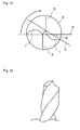
- the shape of the cutting edge can be linear as shown in the schematic view of Fig, 2 , a reentrant curved shape or convex curved shape as shown in Fig. 10 .
- the drilling process at a high revolution rate becomes stable by the convex curved shape cutting edges.
- the shape of the cutting edge can be a convex V-shape as shown in Fig. 13 .
- the convex V-shaped cutting edge 9 comprised a cutting edge portion D and a cutting edge portion E forming the convex V-shape.
- the cutting edge portion D forming a convex V-shape and the cutting edge 1 which does not have a convex V-shape can be positioned in parallel as shown in Fig. 13 .
- the angle ⁇ between the extended line of the line connecting both ends of the cutting edge portion D forming a convex V-shape and the extended line of the line connecting both ends of another cutting edge can be (360/N)° .
- N represents the number of the cutting edges.
- a drill has a spiral flute for excreting drill chips.
- the spiral flute can be either axial asymmetric in accordance with the arrangement of the cutting edges or axial symmetric.
- An axial asymmetric edge drill according to the present invention can be manufactured by trimming the cutting edges of a conventional axial symmetric edge drill.
- a popular drill is a twist drill having a cutting edge shape of right edge -right hand spiral flute, and the cutting edges at the tip portion are axis symmetrically formed as shown in Fig. 1 .
- the axial asymmetrical edge drill used in the embodiment explained below was manufactured by processing a drill for metal processing with axis symmetrically positioned cutting edges at its tip portion that is available in the market.
- a drill according to the present invention is a drill with axial asymmetric cutting edges (if one cutting edge is rotated around the drill shaft center, it does not match with another cutting edge) as shown in Fig. 2 that shows the tip portion image.
- a drill according to the present invention can be an axial asymmetric edge drill having two cutting edge portions as shown in Fig. 3(A) or an axial asymmetric edge drill having the cutting edge 1 made by making a slit in one cutting edge portion as shown in Fig. 3(B) .
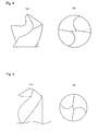
- Fig. 4(A) shows a side view of the tip portion of a single edged drill, wherein the right side cutting edge exists while the left side cutting edge was removed.
- Fig. 4 (B) shows the end face of the single edged drill where the cutting edge is positioned.
- Fig. 5(A) shows a side view of the short chisel drill.
- Fig. 5(B) shows the end face of the short chisel drill where the cutting edges are positioned.
- a process for drilling an object was performed using a drill press. In order to observe the drilled circles formed on the object surface, the drill process stopped before a through hole is made and the shapes of the drilled circles were compared.
- the drilled circles were obtained by changing the angle ⁇ between the extended line of the line connecting both ends of one cutting edge and the extended line of the line connecting both ends of another cutting edge from 5° to 40° in an axial asymmetric cutting edge drill according to the present invention.
- the cutting edge 1 shown in Fig. 3 (A) is made by removing one cutting edge from NACHI STANDARD twist drill with 10mm diameter (two linear cutting edges are positioned in parallel on the end face where the cutting edges are positioned) and making a slit in another remaining cutting edge.
- the drill process was performed by changing the angle ⁇ between the extended line 3 of the line connecting both ends of one cutting edge 1 and the extended line 3 of the line connecting both ends of another cutting edge 1 from 158° to 173° in this axial asymmetric cutting edge drill.
- the drill process was performed using a NACHI STANDARD twist drill with 10mm diameter (two linear cutting edges are positioned in parallel on the end face where the cutting edges are positioned), the single edged drill shown in Fig. 4 and the short chisel drill shown in Fig. 5 as a comparative example.
- An AAG/Aluminum alloy JIS A5052 H112 (called Aluminum alloy, hereinafter) and a JIS C2801 6/4 brass are used as the materials of the objects to be drilled that have different hardness.
- a drill press (NBD-340LR SENSITIVE BENCH DRILL by NAMIKI MACHINE) was used.
- the drilling processes were performed using the apparatus shown in the schematic view of Fig. 6 .
- the constant load of 29.4N was applied to the aluminum alloy object and the constant load of 49.0N was applied to the brass object for the process time of 25 seconds at the revolution rate of 500rpm to obtain equivalent drilled circles.
- a torque sensor 7 was positioned between an object 6 and a three-component dynamometer 8 and the drilling was performed in the direction B.
- the drill revolution direction is indicated by reference "C”.
- the circularity measurement was performed using a three-dimension measurement device (Xyanal 16D by Tokyo Seimitsu). The circularity was measured five times for respective drilled circle at the inlet position by touching the measuring probe at 10 points. An average circularity was obtained.
- "circularity” is defined by the deference between the maximum radius and the minimum radius of a circle and represented in millimeters.
- Fig.7 shows the measurement result for the circularity of the circle obtained by the drill process at a constant load.
- the horizontal axis represents the angle ⁇ between the extended line of the line connecting both ends of one cutting edge and the extended line of the line connecting both ends of another cutting edge of a drill.
- the vertical axis represents the circularity.
- the circularity was measured for the through holes drilled by a NC fries automatic process on the objects at a revolution of 500rpm and a feed of 30mm/min.
- Aluminum alloy objects of 10mm thickness and 1mm thickness and brass objects of 10mm thickness and 1mm thickness were prepared.
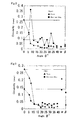
- Fig. 8 shows the circularity measurement result for the aluminum alloy object of 10mm thickness and the brass object of 10mm thickness.
- the horizontal axis represents the angle ⁇ between the extended line of the line connecting both ends of one cutting edge and the extended line of the line connecting both ends of another cutting edge.
- the vertical axis represents the circularity.
- ⁇ represents the result for the single edged drill and " ⁇ ” represents the result for the short chisel drill.
- the value of the circularity is small and it is close to a perfect circle especially in case of ⁇ ⁇ 10° .
- Fig. 9 shows the circularity measurement result for the aluminum alloy object of 1mm thickness and the brass object of 1mm thickness.
- the horizontal axis represents the angle ⁇ between the extended line of the line connecting both ends of one cutting edge and the extended line of the line connecting both ends of another cutting edge.
- the vertical axis represents the circularity.
- ⁇ represents the result for the single edged drill and " ⁇ ” represents the result for the short chisel drill.
- the value of the circularity becomes better in both cases of aluminum alloy and brass as the angle ⁇ becomes larger in comparison with a normal drill as a reference.
- the value of the circularity is small and it is close to a perfect circle especially in case of ⁇ ⁇ 10° .
- the short chisel drill produced a hole with the circularity that is equivalent to that for a normal drill in case of drilling the aluminum alloy object and produced a hole with a circularity that is similar to the case of drilling the brass object.
- the axial asymmetric edge drill with convex curved cutting edges shown in Fig. 10 and the axial asymmetric edge drill with reentrant curved cutting edges shown in Fig. 11 were made by processing a NACHI STANDARD twist drill with 10mm diameter.
- Figs. 14 and 15 show the circularity measurement result for the through hole made by an automatic process using a NC fries on a brass object of 1mm thickness at the programmed revolution of 500rpm and feed speed of 30mm/min.
- Fig. 14 shows a result for the case of using an axial asymmetric edge drill of 0° ⁇ ⁇ ⁇ 40° mentioned above.
- the drill having a convex V-shape cutting edge 9 shown in 13 was made by removing one cutting edge from a NACHI STANDARD twin drill with the diameter of 10mm.
- the angle ⁇ 1 between the cutting edge portion D and the cutting edge portion E of the convex V-shape cutting edge 9 was set to 138° .
- the angle ⁇ 2 between the extended line 3 of the line connecting both ends of the cutting edge portion E of the convex V-shape cutting edge and the extended line 3 of the line connecting both ends of another cutting edge 1 was set to 42° .
- the angle ⁇ 3 between the extended line 3 of the line connecting both ends of the convex V-shape cutting edge 9 and the extended line 3 of the line connecting both ends of another cutting edge 1 was set to larger than 5° and smaller than 175° .
- Fig. 16 shows a circularity measurement result for drilled holes in a 1mm thick brass plate by the convex V-shape edged drill and the short chisel drill.
- the numerals on the horizontal axis represent the angle between the extended line of the line connecting both ends of one cutting edge and the extended line of the line connecting both ends of another cutting edge, and the vertical axis represents the circularity.
- the inlet shape of the drilled hole is close to a perfect circle when the angle ⁇ between the axial asymmetric edges of a drill is in the range of 5° ⁇ ⁇ ⁇ 175° .
- the "Walking Phenomenon" can be improved by setting the angle ⁇ between the extended line of the line connecting both ends of one cutting edge and the extended line of the line connecting both ends of another cutting edge to 40° ⁇ ⁇ ⁇ 158° because the circularity of the drilled hole was improved by the axial asymmetric edge arrangement.
- the number of the cutting edges is not limited to two. It is also considered that a similar result can be obtained by a drill having two or more cutting edges that includes at least one axial asymmetric cutting edge.
- the circularity is improved by misalignment of one of two cutting edge of a drill, e.g. a twist drill, a reamer drill.
- a drill e.g. a twist drill, a reamer drill.
Landscapes
- Engineering & Computer Science (AREA)
- Mechanical Engineering (AREA)
- Drilling Tools (AREA)
Applications Claiming Priority (2)
| Application Number | Priority Date | Filing Date | Title |
|---|---|---|---|
| JP2006046694 | 2006-02-23 | ||
| PCT/JP2007/053992 WO2007097474A1 (ja) | 2006-02-23 | 2007-02-23 | 非軸対称刃ドリル |
Publications (2)
| Publication Number | Publication Date |
|---|---|
| EP1992437A1 true EP1992437A1 (de) | 2008-11-19 |
| EP1992437A4 EP1992437A4 (de) | 2011-07-06 |
Family
ID=38437506
Family Applications (1)
| Application Number | Title | Priority Date | Filing Date |
|---|---|---|---|
| EP07715142A Withdrawn EP1992437A4 (de) | 2006-02-23 | 2007-02-23 | Bohrer mit nicht achssymmetrischem blatt |
Country Status (6)
| Country | Link |
|---|---|
| US (1) | US20090010728A1 (de) |
| EP (1) | EP1992437A4 (de) |
| JP (1) | JPWO2007097474A1 (de) |
| KR (1) | KR20080104333A (de) |
| CN (1) | CN101389432B (de) |
| WO (1) | WO2007097474A1 (de) |
Cited By (2)
| Publication number | Priority date | Publication date | Assignee | Title |
|---|---|---|---|---|
| WO2010102705A1 (de) * | 2009-03-11 | 2010-09-16 | Kennametal Inc. | Bohrerspitze sowie bohrwerkzeug mit einer bohrerspitze |
| EP2942135A1 (de) * | 2014-05-07 | 2015-11-11 | European Aeronautic Defence and Space Company - EADS France | Verfahren zum Bohren eines Materialstapels, entsprechender Bohrer und Bohrvorrichtung |
Families Citing this family (10)
| Publication number | Priority date | Publication date | Assignee | Title |
|---|---|---|---|---|
| JP2009255251A (ja) * | 2008-04-18 | 2009-11-05 | Tokyo Univ Of Agriculture & Technology | ツイストドリル |
| CN103357939A (zh) * | 2012-04-03 | 2013-10-23 | 鸿富锦精密工业(深圳)有限公司 | 铣刀 |
| JP2016041464A (ja) * | 2014-08-18 | 2016-03-31 | 株式会社アストロテック | ドライアイス粉末噴射型冷却方法および冷却装置 |
| CN105868455B (zh) * | 2016-03-25 | 2019-01-22 | 哈尔滨理工大学 | 刀具左右切削刃分层切削差异性分析方法 |
| CN107639245A (zh) * | 2017-10-30 | 2018-01-30 | 舟山飞达工具有限公司 | 一种多功能合金刀片 |
| WO2020250499A1 (ja) * | 2019-06-13 | 2020-12-17 | 住友電工ハードメタル株式会社 | 切削工具 |
| JP6714248B1 (ja) * | 2019-11-06 | 2020-06-24 | 株式会社ジーベックテクノロジー | 面取りカッターおよびワークの面取り方法 |
| CN112809055B (zh) * | 2021-02-02 | 2026-03-27 | 苏州沃钛工业技术有限公司 | 单孔限位可换钻尖 |
| CN115319158B (zh) * | 2022-08-25 | 2025-08-29 | 广东鼎泰高科技术股份有限公司 | 钻孔工具及盲孔加工方法 |
| CN121315306A (zh) * | 2024-02-18 | 2026-01-13 | 上海钰工工具有限公司 | 用于孔加工工具的钻削部和孔加工工具 |
Family Cites Families (28)
| Publication number | Priority date | Publication date | Assignee | Title |
|---|---|---|---|---|
| US1407546A (en) * | 1919-10-15 | 1922-02-21 | Joseph Felix Alexander | Twist drill |
| US2795979A (en) * | 1954-07-14 | 1957-06-18 | Gen Motors Corp | Chatterless countersink cutter |
| SE411310B (sv) * | 1976-11-17 | 1979-12-17 | Sandvik Ab | Borr, foretredesvis med vendsker |
| JPS5555312U (de) * | 1978-10-11 | 1980-04-15 | ||
| JPS5555312A (en) * | 1978-10-20 | 1980-04-23 | Ricoh Co Ltd | Simultaneous multibeam light modulating system |
| JPS63114808A (ja) * | 1986-10-31 | 1988-05-19 | Izumo Sangyo Kk | ドリル |
| JPH0767646B2 (ja) * | 1986-11-05 | 1995-07-26 | 三菱マテリアル株式会社 | ドリル |
| CH670968A5 (de) * | 1986-11-25 | 1989-07-31 | Sphinxwerke Mueller Ag | |
| US4756650A (en) * | 1986-11-26 | 1988-07-12 | Kabushiki Kaisha Kobe Seiko Sho | Twist drill |
| DE3805729A1 (de) * | 1988-02-24 | 1989-08-31 | Krauss Helmut | Bohr- oder reibwerkzeug |
| JP2603993B2 (ja) * | 1988-03-11 | 1997-04-23 | 俊明 細井 | ドリル |
| JPH02198707A (ja) * | 1989-01-24 | 1990-08-07 | Masao Kubota | ドリル |
| DE3930225A1 (de) * | 1989-09-11 | 1991-03-14 | Maier Kg Andreas | Bohrer und verwendung eines bohrers |
| JPH0451318A (ja) * | 1990-06-20 | 1992-02-19 | Canon Inc | 画像処理装置 |
| JPH0451318U (de) * | 1990-08-31 | 1992-04-30 | ||
| JP2981055B2 (ja) | 1992-04-28 | 1999-11-22 | 富士精工株式会社 | バニシングドリル |
| JPH08155715A (ja) | 1994-12-06 | 1996-06-18 | Taishi Seiko Kk | ドリルリーマ |
| WO1997004908A1 (en) * | 1995-07-27 | 1997-02-13 | Mays Ralph C | Drill bit |
| DE19726984A1 (de) * | 1997-06-25 | 1999-01-07 | Kennametal Inc | Bohrer zum Trockenbohren |
| US6283682B1 (en) * | 1997-09-30 | 2001-09-04 | Jerald D. Plummer | Helically fluted twist drill device |
| SE517946C2 (sv) * | 1999-07-14 | 2002-08-06 | Seco Tools Ab | Borrenhet med tre skär samt kylkanal |
| DE10021879A1 (de) * | 2000-05-05 | 2001-11-08 | Komet Stahlhalter Werkzeuge | Vollbohrer für Werkzeugmaschinen |
| JP2002361509A (ja) | 2001-06-05 | 2002-12-18 | Koyo Giken Kk | リーマ付ドリル |
| JP2005246577A (ja) | 2004-03-08 | 2005-09-15 | Hitachi Tool Engineering Ltd | バリ除去ドリル |
| KR100929018B1 (ko) * | 2005-03-07 | 2009-11-27 | 가부시키 가이샤 미야나가 | 드릴 비트 |
| DE102006025294B4 (de) * | 2006-05-31 | 2010-07-22 | Kennametal Inc. | Bohrwerkzeug |
| JP2008062620A (ja) * | 2006-09-11 | 2008-03-21 | Miyanaga:Kk | ドリルビット |
| DE102007050050A1 (de) * | 2007-10-17 | 2009-04-23 | Kennametal Inc. | Rundlaufwerkzeug, insbesondere Bohrer |
-
2007
- 2007-02-23 JP JP2008501792A patent/JPWO2007097474A1/ja active Pending
- 2007-02-23 EP EP07715142A patent/EP1992437A4/de not_active Withdrawn
- 2007-02-23 US US12/224,301 patent/US20090010728A1/en not_active Abandoned
- 2007-02-23 CN CN200780006436XA patent/CN101389432B/zh not_active Expired - Fee Related
- 2007-02-23 KR KR1020087023160A patent/KR20080104333A/ko not_active Ceased
- 2007-02-23 WO PCT/JP2007/053992 patent/WO2007097474A1/ja not_active Ceased
Cited By (4)
| Publication number | Priority date | Publication date | Assignee | Title |
|---|---|---|---|---|
| WO2010102705A1 (de) * | 2009-03-11 | 2010-09-16 | Kennametal Inc. | Bohrerspitze sowie bohrwerkzeug mit einer bohrerspitze |
| US10086444B2 (en) | 2009-03-11 | 2018-10-02 | Kennametal Inc. | Drill tip and drilling tool having a drill tip |
| EP2942135A1 (de) * | 2014-05-07 | 2015-11-11 | European Aeronautic Defence and Space Company - EADS France | Verfahren zum Bohren eines Materialstapels, entsprechender Bohrer und Bohrvorrichtung |
| US9649699B2 (en) | 2014-05-07 | 2017-05-16 | Airbus Group Sas | Method for drilling a stack of materials, drill bit and drilling device |
Also Published As
| Publication number | Publication date |
|---|---|
| EP1992437A4 (de) | 2011-07-06 |
| JPWO2007097474A1 (ja) | 2009-07-16 |
| CN101389432B (zh) | 2011-08-31 |
| CN101389432A (zh) | 2009-03-18 |
| KR20080104333A (ko) | 2008-12-02 |
| WO2007097474A1 (ja) | 2007-08-30 |
| US20090010728A1 (en) | 2009-01-08 |
Similar Documents
| Publication | Publication Date | Title |
|---|---|---|
| EP1992437A1 (de) | Bohrer mit nicht achssymmetrischem blatt | |
| EP2098319B1 (de) | Verfahren zur anordnung von schneideinsätzen in einem bohrer | |
| WO2010143595A1 (ja) | 穴あけ工具 | |
| CN101511513B (zh) | 模块式钻孔工具及其制造方法 | |
| US10695846B2 (en) | Interpolated milling methods | |
| EP2298477A1 (de) | Bohrer, schneideinsatz und verfahren zur herstellung eines geschnittenen objekts | |
| US7278806B1 (en) | Two edge deburring tool | |
| US10926344B2 (en) | Taper reamer | |
| EP2952277A1 (de) | Verfahren zur herstellung eines zerspanungswerkzeugs sowie zerspanungswerkzeug | |
| US20160346846A1 (en) | Drill and method of drilling a hole | |
| JP2011073129A (ja) | 穴あけ用ドリル | |
| US20100104386A1 (en) | Grooving work method and grooving work apparatus | |
| CA2879928A1 (en) | Cutting tool and corresponding assembly | |
| KR20220110591A (ko) | 계단식 커팅 팁을 갖는 트위스트 드릴 비트 | |
| US8366359B2 (en) | Method for machining crankshafts and device for carrying out this method | |
| JP6458851B1 (ja) | リーマ | |
| JPH09117914A (ja) | 切り屑排出用の溝を有するドリルの刃 | |
| US20060099042A1 (en) | Method for producing elements from phase change material | |
| JP3474549B2 (ja) | エンドミルによる溝加工方法 | |
| JP2016147328A (ja) | ドリル | |
| RU68394U1 (ru) | Сверло со сменными многогранными пластинами | |
| JP2022171044A (ja) | 切削工具 | |
| JP2002263902A (ja) | 切削加工方法 | |
| JP2010036295A (ja) | ドリル及びドリルの製造方法 | |
| JP2002028810A (ja) | 小型ドリル |
Legal Events
| Date | Code | Title | Description |
|---|---|---|---|
| PUAI | Public reference made under article 153(3) epc to a published international application that has entered the european phase |
Free format text: ORIGINAL CODE: 0009012 |
|
| 17P | Request for examination filed |
Effective date: 20080919 |
|
| AK | Designated contracting states |
Kind code of ref document: A1 Designated state(s): DE IT |
|
| RBV | Designated contracting states (corrected) |
Designated state(s): DE IT |
|
| RAP1 | Party data changed (applicant data changed or rights of an application transferred) |
Owner name: TOKYO UNIVERSITY OF AGRICULTURE AND TECHNOLOGY TLO |
|
| A4 | Supplementary search report drawn up and despatched |
Effective date: 20110607 |
|
| DAX | Request for extension of the european patent (deleted) | ||
| 17Q | First examination report despatched |
Effective date: 20130905 |
|
| STAA | Information on the status of an ep patent application or granted ep patent |
Free format text: STATUS: THE APPLICATION IS DEEMED TO BE WITHDRAWN |
|
| 18D | Application deemed to be withdrawn |
Effective date: 20130903 |