EP1992541A2 - Dispositif de surveillance pour les essieux de véhicules sur rail - Google Patents
Dispositif de surveillance pour les essieux de véhicules sur rail Download PDFInfo
- Publication number
- EP1992541A2 EP1992541A2 EP08008542A EP08008542A EP1992541A2 EP 1992541 A2 EP1992541 A2 EP 1992541A2 EP 08008542 A EP08008542 A EP 08008542A EP 08008542 A EP08008542 A EP 08008542A EP 1992541 A2 EP1992541 A2 EP 1992541A2
- Authority
- EP
- European Patent Office
- Prior art keywords
- rail
- threshold
- microphones
- reaction force
- sensors
- Prior art date
- Legal status (The legal status is an assumption and is not a legal conclusion. Google has not performed a legal analysis and makes no representation as to the accuracy of the status listed.)
- Withdrawn
Links
- 238000012806 monitoring device Methods 0.000 title description 8
- 238000001514 detection method Methods 0.000 claims abstract description 6
- 238000011156 evaluation Methods 0.000 claims description 15
- 238000012544 monitoring process Methods 0.000 claims description 5
- 241001669679 Eleotris Species 0.000 abstract description 2
- 239000000835 fiber Substances 0.000 description 5
- 230000003137 locomotive effect Effects 0.000 description 4
- 238000005259 measurement Methods 0.000 description 4
- 230000002950 deficient Effects 0.000 description 2
- 230000002411 adverse Effects 0.000 description 1
- 238000012937 correction Methods 0.000 description 1
- 230000001419 dependent effect Effects 0.000 description 1
- 238000013461 design Methods 0.000 description 1
- 230000006870 function Effects 0.000 description 1
- 238000012986 modification Methods 0.000 description 1
- 230000004048 modification Effects 0.000 description 1
- 238000005096 rolling process Methods 0.000 description 1
- 230000001960 triggered effect Effects 0.000 description 1
Images
Classifications
-
- B—PERFORMING OPERATIONS; TRANSPORTING
- B61—RAILWAYS
- B61K—AUXILIARY EQUIPMENT SPECIALLY ADAPTED FOR RAILWAYS, NOT OTHERWISE PROVIDED FOR
- B61K9/00—Railway vehicle profile gauges; Detecting or indicating overheating of components; Apparatus on locomotives or cars to indicate bad track sections; General design of track recording vehicles
- B61K9/12—Measuring or surveying wheel-rims
-
- B—PERFORMING OPERATIONS; TRANSPORTING
- B61—RAILWAYS
- B61K—AUXILIARY EQUIPMENT SPECIALLY ADAPTED FOR RAILWAYS, NOT OTHERWISE PROVIDED FOR
- B61K9/00—Railway vehicle profile gauges; Detecting or indicating overheating of components; Apparatus on locomotives or cars to indicate bad track sections; General design of track recording vehicles
- B61K9/04—Detectors for indicating the overheating of axle bearings and the like, e.g. associated with the brake system for applying the brakes in case of a fault
- B61K9/06—Detectors for indicating the overheating of axle bearings and the like, e.g. associated with the brake system for applying the brakes in case of a fault by detecting or indicating heat radiation from overheated axles
Definitions
- the invention relates to a device for monitoring the wheelsets of passing rail vehicles, consisting of at least one within a limited by rail contacts measuring section below each rail of a rail track used in a threshold and connected to an evaluation unit IR receiving unit.
- IR measuring systems are used with at least one IR receiving unit, which are housed below the rail track in a hollow sleeper or a specially trained measuring threshold. In most cases, however, four IR receiving units are provided in such a threshold, via which the temperatures of all wheelset bearings of a wheelset can be detected.
- the values determined in this case are usually compared with the values or infrared signal patterns which are stored in an evaluation unit, for example a computer. In case of impermissible deviations, an alarm signal is emitted.
- the invention is therefore based on the object of further developing a known device for monitoring the wheelsets of passing rail vehicles so that the danger emanating from hot rotors on wheelset bearings on rail vehicles is further reduced.
- a particular advantage of the device according to the invention results when each rail of a rail track is assigned a respective camera.
- the device according to the invention can be completed in a particularly simple manner if the same is assigned to a so-called flat-point locating device, which is formed from a plurality of threshold reaction force sensors, each of which is always associated with a threshold.
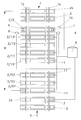
- a system for monitoring the wheelsets of passing rail vehicles in particular a railway train, is shown systemically, which shows a plan view of a rail track 1, which consists of two rails 1a and 1b, which in turn are mounted on a plurality of sleepers 2.
- thresholds 2a and 2b in the region of the drawing include a measuring range M, which is delimited at both ends by at least one rail contact 3, 4.
- These rail contacts 3, 4 are advantageously designed as fiber optic sensors and serve to turn on or off the monitoring device located within the measuring section M.
- a train not shown, moves in the direction of an arrow 5, so that the rail contact 3, the monitoring device turns on while it is switched off again via the switching contact 4.
- the monitoring device consists first of the measuring section M of an evaluation unit with a computer and a data memory, which are housed together in a kind of switching house S and advantageously linked together with other monitoring devices and connected to a supra-local monitoring center.
- two IR receiving units 6, 7 are connected to this evaluation unit, which are each located in a housing, which are advantageously used via attenuators in a threshold 2/2.
- This threshold 2/2 is designed as a measuring or hollow threshold.
- the mentioned attenuators have the task of precluding the inevitably occurring during the crossing of a train over the threshold 2/2 vibrations in a disturbing manner to the housing and accommodated therein and sensitive to vibration components, in particular the IR receiving units 6, 7 arrive and can bring adverse consequences here.
- the IR receiving units 6, 7 By means of these IR receiving units 6, 7, the temperatures of the wheelset bearings of the vehicles rolling over them are measured and compared with predetermined values and / or infrared signal patterns stored in the evaluation unit. In case of impermissible deviations, an alarm signal is emitted.
- the threshold 2/2 on each side outside the rail track or outside of the track bed a microphone 8, 9 assigned, which are advantageously designed as a particularly sensitive directional microphones.
- the running noise of the individual wheels of the wheelsets of each rail vehicle are detected and also supplied to the evaluation unit.
- the detected noises are compared with advantageously stored acoustic patterns.
- an alarm signal is also triggered.
- a comparison is also made with the values which the IR receiving units 6, 7 have detected. With such a comparison, it is already possible to determine very early on whether any damage to the wheel bearing sets could possibly be announced.
- the threshold 2/2 for example, outside of the track bed or side of the rail 1b also associated with a detection unit 10 formed by a camera.
- this detection unit 10 the nature of the individual parts, such as the locomotive and wagons, the rail vehicle is detected very accurately. This makes it possible to assign the determined noises of the individual wheel bearings to the different locomotive and wagon types and to associate the corresponding locomotive and wagon types in a particularly good manner with the corresponding acoustic patterns of acoustic patterns and for future measurements save.
- the monitoring device according to the invention is also capable of learning due to its design.
- the monitoring device is supplemented by a flat-point location unit.
- a flat-point location unit This extends in the present embodiment, for example, thirteen thresholds 2/01 to 2/13, but not all of which are shown.
- a threshold reaction sensor 11 is located below each rail 1a and 1b in the area of each threshold 2/01 to 2/13.
- These threshold-reaction sensors 11 are also advantageously designed as fiber-optic sensors.
- the threshold reaction sensors 11 are advantageously accommodated between a support plate carrying the rail 1a, 1b and the threshold 2/01 to 2/13.
- the values determined here are also fed to the evaluation unit and stored there. Deviations from predefined values also trigger an alarm signal here.
- fiber optic sensors When using fiber optic sensors as threshold reaction sensors 11, it is expedient to assign a temperature sensor in the region of each rail to at least one of the thresholds 2/01 to 2/13. Namely, fiber optic sensors have the peculiarity that the measurement results change with the same force or the same weight of an impeller as a function of the temperature or ambient temperature of the fiber optic sensors, which influences the measurement results. The measurement results of the temperature sensors are also fed to the evaluation unit and used there for the correction of the determined values of the fiber optic sensors.
- the distance between the threshold 2/01 and the threshold 2/13 has advantageously twice the length as the circumference of the largest, the rail track moving impeller. This length is about 7.80 m. Such a long length has the advantage that each impeller can be checked twice for any existing flats.
- the distance between the threshold 2a carrying the rail contacts 3 and the first threshold 2/01 with the threshold reaction sensors 3 may be about 30m to 80m. The same applies to the distance between the threshold 2/2 with the IR receiving units 6,7 and the threshold 2b with the rail contacts. 4
- the microphones 8, 9 and / or the recognition unit 10 can also be arranged in the area of other thresholds 2.
- the rail contacts 3,4 and / or the threshold reaction sensors 11 may also be designed differently.
- the order of the individual parts - except the rail contacts 3,4 - the monitoring device can also be chosen differently.
Landscapes
- Engineering & Computer Science (AREA)
- Mechanical Engineering (AREA)
- Measurement Of Mechanical Vibrations Or Ultrasonic Waves (AREA)
- Rolling Contact Bearings (AREA)
- Radiation Pyrometers (AREA)
Applications Claiming Priority (1)
| Application Number | Priority Date | Filing Date | Title |
|---|---|---|---|
| DE200720006904 DE202007006904U1 (de) | 2007-05-14 | 2007-05-14 | Überwachungsvorrichtung für die Radsätze von Schienenfahrzeuge |
Publications (2)
| Publication Number | Publication Date |
|---|---|
| EP1992541A2 true EP1992541A2 (fr) | 2008-11-19 |
| EP1992541A3 EP1992541A3 (fr) | 2009-08-19 |
Family
ID=38289383
Family Applications (1)
| Application Number | Title | Priority Date | Filing Date |
|---|---|---|---|
| EP08008542A Withdrawn EP1992541A3 (fr) | 2007-05-14 | 2008-05-07 | Dispositif de surveillance pour les essieux de véhicules sur rail |
Country Status (2)
| Country | Link |
|---|---|
| EP (1) | EP1992541A3 (fr) |
| DE (1) | DE202007006904U1 (fr) |
Cited By (2)
| Publication number | Priority date | Publication date | Assignee | Title |
|---|---|---|---|---|
| CN109532938A (zh) * | 2019-01-11 | 2019-03-29 | 北京铁道工程机电技术研究所股份有限公司 | 一种救援悬轮监控装置 |
| DE102022114034A1 (de) | 2022-06-02 | 2023-12-07 | Deutsche Bahn Aktiengesellschaft | Überwachungseinheit und überwachungseinrichtung |
Families Citing this family (2)
| Publication number | Priority date | Publication date | Assignee | Title |
|---|---|---|---|---|
| DE102009018036B4 (de) | 2009-04-18 | 2014-02-06 | Iakov Fridman | Vorrichtung zur Vorbeugung von Zugkatastrophen aufgrund beschädigter Eisenbahnwagenradsätze sowie Verwendung dieser Vorrichtung |
| DE102020127311A1 (de) * | 2020-10-16 | 2022-04-21 | BEN-INNOVA Systemtechnik GmbH | Vorrichtung zur Festbrems- und/oder Heißläuferortung bei Schienenfahrzeugen und System mit einer Vorrichtung zur Festbrems- und/oder Heißläuferortung und zumindest einer Schwelle zur Auflage von Schienen |
Citations (1)
| Publication number | Priority date | Publication date | Assignee | Title |
|---|---|---|---|---|
| DE202005015790U1 (de) | 2005-10-07 | 2005-12-29 | Neuroth, Bernd | Temperatur-Überwachungsvorrichtung für Radsatzlager |
Family Cites Families (5)
| Publication number | Priority date | Publication date | Assignee | Title |
|---|---|---|---|---|
| US4790190A (en) * | 1987-10-02 | 1988-12-13 | Servo Corporation Of America | On-line acoustic detection of bearing defects |
| GB2367365B (en) * | 2000-10-02 | 2002-08-14 | Strainstall Engineering Servic | Measuring train parameters |
| DE10122183B4 (de) * | 2001-05-08 | 2004-02-26 | Rolf Käufer | Unfall-/Brandschutz bei Fahrzeugen |
| DE10305470A1 (de) * | 2003-02-13 | 2004-08-26 | Schenck Process Gmbh | Meßstrecke zur Erfassung unterschiedlicher physikalischer Größen schienengebundener Fahrzeuge |
| DE202006005190U1 (de) * | 2006-03-31 | 2006-06-22 | Neuroth, Bernd, Tres Cantos | Anordnung zur Überprüfung der Laufräder von Schienenfahrzeugen |
-
2007
- 2007-05-14 DE DE200720006904 patent/DE202007006904U1/de not_active Expired - Lifetime
-
2008
- 2008-05-07 EP EP08008542A patent/EP1992541A3/fr not_active Withdrawn
Patent Citations (1)
| Publication number | Priority date | Publication date | Assignee | Title |
|---|---|---|---|---|
| DE202005015790U1 (de) | 2005-10-07 | 2005-12-29 | Neuroth, Bernd | Temperatur-Überwachungsvorrichtung für Radsatzlager |
Cited By (2)
| Publication number | Priority date | Publication date | Assignee | Title |
|---|---|---|---|---|
| CN109532938A (zh) * | 2019-01-11 | 2019-03-29 | 北京铁道工程机电技术研究所股份有限公司 | 一种救援悬轮监控装置 |
| DE102022114034A1 (de) | 2022-06-02 | 2023-12-07 | Deutsche Bahn Aktiengesellschaft | Überwachungseinheit und überwachungseinrichtung |
Also Published As
| Publication number | Publication date |
|---|---|
| EP1992541A3 (fr) | 2009-08-19 |
| DE202007006904U1 (de) | 2007-07-19 |
Similar Documents
| Publication | Publication Date | Title |
|---|---|---|
| DE69717763T2 (de) | Verfahren und Vorrichtung zur Initialisierung eines automatisierten Zugsteuerungssystems | |
| DE10260816B4 (de) | Messeinrichtung zum Messen der Rundheit eines Eisenbahnrades | |
| EP3116762B1 (fr) | Dispositif de detection d'obstacles pour véhicules ferroviaires | |
| EP1839990B1 (fr) | Dispositif pour la vérification des roues d'un véhicule ferroviaire | |
| DE102016108273A1 (de) | Verfahren zur Auswertung von Signalen wenigstens eines Vibrationssensors | |
| EP3310637B1 (fr) | Dispositif de contrôle et procédé de contrôle d'un profil défini d'un convoi composé de véhicules, notamment de véhicules ferroviaires | |
| EP1992541A2 (fr) | Dispositif de surveillance pour les essieux de véhicules sur rail | |
| EP0265538B1 (fr) | Dispositif pour la mesure sans contact des températures des freins de voitures de chemin de fer qui passent | |
| EP2647543B1 (fr) | Système de détection de caractéristiques de véhicules ferroviaires passant | |
| EP2542870B1 (fr) | Traverse pour la pose de rails | |
| DE4432329C2 (de) | Vorrichtung zur Zuglaufüberwachung und Fahrwegüberwachung | |
| DE202008012250U1 (de) | Temperatur-Überwachungsvorrichtung für Radlager von Schienenfahrzeugen | |
| WO2008006803A1 (fr) | Système, en particulier système de trafic ferroviaire à petite distance, et procédé pour la détection du trajet côté véhicule pour un tel système | |
| EP1772342B1 (fr) | Dispositif de surveillance de la température de boîtes d'essieux | |
| DE102008008578B3 (de) | Ermittlung der dynamischen Radkraft eines Eisenbahnfahrzeugs auf das Herzstück einer Weiche | |
| WO2019057421A1 (fr) | Détection et optimisation de la précision de point d'arrêt d'un véhicule | |
| EP2522966A2 (fr) | Dispositif et procédé de détermination dýun seuil d'émissions sonores | |
| AT14280U1 (de) | Vorrichtung zum Messen der Lage von Schienen eines Gleises | |
| DE19851931A1 (de) | Anordnung zur Erkennung von Schienenbrüchen und Eisenbahnschiene | |
| EP1227023B1 (fr) | Procédé pour produire un signal d'alarme en relation avec un endommagement d'un palier d'arbre | |
| EP1447679B1 (fr) | Dispositif et procédé pour mesurer la distance entre deux points d'un objet, en particulier pour mesurer le diamètre d'une roue d'un véhicule ferroviaire | |
| EP2870048B1 (fr) | Localisation de véhicule ferroviaire | |
| DE202008010664U1 (de) | Prüfstand zur Prüfung von Stromabnehmern | |
| DE102007044796A1 (de) | Messverfahren zur Bestimmung von Emissionen | |
| DE102006033210A1 (de) | System und Verfahren zur Bestimmung der momentanen Ortsposition von Fahrzeugen, insbesondere von Zügen |
Legal Events
| Date | Code | Title | Description |
|---|---|---|---|
| PUAI | Public reference made under article 153(3) epc to a published international application that has entered the european phase |
Free format text: ORIGINAL CODE: 0009012 |
|
| AK | Designated contracting states |
Kind code of ref document: A2 Designated state(s): AT BE BG CH CY CZ DE DK EE ES FI FR GB GR HR HU IE IS IT LI LT LU LV MC MT NL NO PL PT RO SE SI SK TR |
|
| AX | Request for extension of the european patent |
Extension state: AL BA MK RS |
|
| PUAL | Search report despatched |
Free format text: ORIGINAL CODE: 0009013 |
|
| AK | Designated contracting states |
Kind code of ref document: A3 Designated state(s): AT BE BG CH CY CZ DE DK EE ES FI FR GB GR HR HU IE IS IT LI LT LU LV MC MT NL NO PL PT RO SE SI SK TR |
|
| AX | Request for extension of the european patent |
Extension state: AL BA MK RS |
|
| AKX | Designation fees paid |
Designated state(s): AT BE BG CH CY CZ DE DK EE ES FI FR GB GR HR HU IE IS IT LI LT LU LV MC MT NL NO PL PT RO SE SI SK TR |
|
| STAA | Information on the status of an ep patent application or granted ep patent |
Free format text: STATUS: THE APPLICATION IS DEEMED TO BE WITHDRAWN |
|
| 18D | Application deemed to be withdrawn |
Effective date: 20100220 |