EP1993864B1 - Kühlkanal für eine hlk-gebläseanordnung für fahrzeuge - Google Patents
Kühlkanal für eine hlk-gebläseanordnung für fahrzeuge Download PDFInfo
- Publication number
- EP1993864B1 EP1993864B1 EP07717277A EP07717277A EP1993864B1 EP 1993864 B1 EP1993864 B1 EP 1993864B1 EP 07717277 A EP07717277 A EP 07717277A EP 07717277 A EP07717277 A EP 07717277A EP 1993864 B1 EP1993864 B1 EP 1993864B1
- Authority
- EP
- European Patent Office
- Prior art keywords
- motor
- blower
- cooling air
- air path
- inlet
- Prior art date
- Legal status (The legal status is an assumption and is not a legal conclusion. Google has not performed a legal analysis and makes no representation as to the accuracy of the status listed.)
- Not-in-force
Links
Images




Classifications
-
- B—PERFORMING OPERATIONS; TRANSPORTING
- B60—VEHICLES IN GENERAL
- B60H—ARRANGEMENTS OF HEATING, COOLING, VENTILATING OR OTHER AIR-TREATING DEVICES SPECIALLY ADAPTED FOR PASSENGER OR GOODS SPACES OF VEHICLES
- B60H1/00—Heating, cooling or ventilating devices
-
- B—PERFORMING OPERATIONS; TRANSPORTING
- B60—VEHICLES IN GENERAL
- B60H—ARRANGEMENTS OF HEATING, COOLING, VENTILATING OR OTHER AIR-TREATING DEVICES SPECIALLY ADAPTED FOR PASSENGER OR GOODS SPACES OF VEHICLES
- B60H1/00—Heating, cooling or ventilating devices
- B60H1/00457—Ventilation unit, e.g. combined with a radiator
- B60H1/00471—The ventilator being of the radial type, i.e. with radial expulsion of the air
-
- B—PERFORMING OPERATIONS; TRANSPORTING
- B60—VEHICLES IN GENERAL
- B60H—ARRANGEMENTS OF HEATING, COOLING, VENTILATING OR OTHER AIR-TREATING DEVICES SPECIALLY ADAPTED FOR PASSENGER OR GOODS SPACES OF VEHICLES
- B60H1/00—Heating, cooling or ventilating devices
- B60H1/32—Cooling devices
-
- F—MECHANICAL ENGINEERING; LIGHTING; HEATING; WEAPONS; BLASTING
- F04—POSITIVE - DISPLACEMENT MACHINES FOR LIQUIDS; PUMPS FOR LIQUIDS OR ELASTIC FLUIDS
- F04D—NON-POSITIVE-DISPLACEMENT PUMPS
- F04D25/00—Pumping installations or systems
- F04D25/02—Units comprising pumps and their driving means
- F04D25/08—Units comprising pumps and their driving means the working fluid being air, e.g. for ventilation
- F04D25/082—Units comprising pumps and their driving means the working fluid being air, e.g. for ventilation the unit having provision for cooling the motor
-
- F—MECHANICAL ENGINEERING; LIGHTING; HEATING; WEAPONS; BLASTING
- F04—POSITIVE - DISPLACEMENT MACHINES FOR LIQUIDS; PUMPS FOR LIQUIDS OR ELASTIC FLUIDS
- F04D—NON-POSITIVE-DISPLACEMENT PUMPS
- F04D29/00—Details, component parts, or accessories
- F04D29/58—Cooling; Heating; Diminishing heat transfer
- F04D29/5806—Cooling the drive system
-
- F—MECHANICAL ENGINEERING; LIGHTING; HEATING; WEAPONS; BLASTING
- F04—POSITIVE - DISPLACEMENT MACHINES FOR LIQUIDS; PUMPS FOR LIQUIDS OR ELASTIC FLUIDS
- F04D—NON-POSITIVE-DISPLACEMENT PUMPS
- F04D29/00—Details, component parts, or accessories
- F04D29/70—Suction grids; Strainers; Dust separation; Cleaning
- F04D29/701—Suction grids; Strainers; Dust separation; Cleaning especially adapted for elastic fluid pumps
- F04D29/706—Humidity separation
Definitions
- This invention relates generally to centrifugal blowers, and more particularly to centrifugal blowers for use in automotive climate control systems.
- Centrifugal blowers typically include impellers having a plurality of blades that redirect an incoming airflow toward a radial direction as the airflow moves from the impeller inlet to the impeller outlet.
- the blades are typically attached to a hub for rotation therewith.
- An electric motor rotates the impeller at the required speed. The electric motor requires cooling and therefore has an airflow path through the motor.
- the present invention provides a motor cooling air path that prevents water from entering the motor, even if the assembly is tilted up to twenty-five degrees from its installed position. This is achieved by designing the air path with an incline or change in elevation that prevents water from traveling over the top of the incline and into the motor.
- the pressure differential between the cooling path inlet in the volute and outlet at the drive end of the motor drive the air over the incline and through the motor.
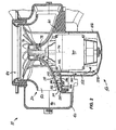
- the motor flange 60 is connected to the blower housing 40 and cooperates with the blower housing to form the volute, as described above.
- the motor flange 60 has a generally bell-shaped surface 110 that forms part of the volute and that is in closely-spaced, facing relationship with the lower edges of the fan blades.
- the motor flange 60 also has a generally cylindrical surface 114 that extends generally parallel to, or is centered on, the axis 74, and that extends downwardly from the lower end of the bell-shaped surface 110.
- the blower 10 also includes a cooling air path (indicated by the arrows in FIG. 2 ) defined in the illustrated construction by the motor flange 60 and by the cover 106. It will be understood by those skilled in the art that the cooling air path could be defined by other parts of the blower.
- the cooling air path has an inlet 124 located in the surface 114 of the motor flange 60, so that the inlet 124 communicates with the interior space 90 of the volute.
- the inlet 124 is located near the upper edge of the surface 114.
- the inlet can be located near the lower edge of the surface 114, or somewhere in between.
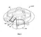
- FIG. 5 shows the inlet 124 near the lower edge of the surface
- FIG. 14 shows another construction with the inlet 124 near the upper edge of the surface.
- the cooling air path also has a downstream portion 152 that extends axially or downwardly from the radially inward end of the upstream portion 132, and that extends substantially the entire length of motor 30.
- the downstream portion 152 is defined on the outside by the cover 106 and on the inside by the cylindrical portion 102 of the flange 60 and by the motor 30.
- the cover 106 includes an axial portion 162 that extends upwardly and over the cylindrical portion 102 of the motor flange 60. Extending outwardly and downwardly from the upper end of the axial portion 162 is an angled portion 166 that includes the ramped surface 136.
- the cooling air path substantially prevents water from entering the motor 30, even if the blower 10 is tilted up to twenty-five degrees (in any direction) from its installed position.
- FIGS. 3 through 5 partially illustrate another embodiment of the invention. Common elements have been given the same reference numerals, although the construction of the common elements may differ somewhat.
- a blower assembly 200 includes two parts, a motor flange 60 and an end cover or cap 106. These two parts are assembled to form an enclosed cooling air path from the volute to the end of the motor 30 opposite the drive shaft.
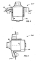
- FIG. 3 shows the direction of the cooling airflow.
- FIG. 3 shows the cover 106 forming an inclined surface 136 which starts at a low elevation at the inlet end 124 of the cooling channel and which then progresses to a higher elevation before turning again towards the "bottom" of the motor. The direction of gravity is downward in FIG 3 .
- FIG. 3 Many automotive HVAC blower assemblies are oriented as in FIG. 3 , with the motor shaft vertical. Others are oriented with the motor shaft horizontal as in FIG. 4 .
- the cooling hole or inlet 124 is positioned facing downward, but can in fact be positioned in any direction when the axis 74 is horizontal.
- water must enter through the fan inlet 94. The water then falls down towards the outer wall of the volute and away from the inner wall of the volute where the motor cooling hole is located.
- the blower is positioned with the axis 74 other than horizontal or vertical, it is preferable to have the inlet 124 directly below the axis 74, or in its lowermost possible position.
- This lowermost position can also be described as having the inlet 124 below the axis 74 and in a vertical plane (e.g., the plane of the paper in FIG. 4 ) including the axis 74. Putting the inlet 124 in this lowermost position minimizes the likelihood of water entering the inlet 124, because any water that has entered the blower inlet 94 will tend to flow away from the cooling air path inlet 124, which in its lowermost position faces at least somewhat downwardly.
- the inlet 124 can be located in a second plane including the axis 74, with the angle between the second plane and the vertical plane of the axis 74 being less than about fifteen degrees. In other words, the blower can be rotated about the axis 74 up to about fifteen degrees in either direction.
- FIG. 6 shows an alternative blower 300. Common elements again have the same reference numerals.
- the blower 300 has a cooling air path (indicated by arrows) including a water reservoir 304 adjacent the cooling air path inlet 124.
- the water reservoir 304 collects water that may enter the inlet to further prevent water from passing through the cooling air path.
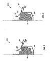
- FIG. 9 shows an alternative blower 600.
- the upstream portion 132 of the cooling air path has a ramped surface 136, a dam 148 and a wall 144.
- FIG. 10 shows an alternative blower 700.
- the "roof" of the upstream portion 132 is generally horizontal, resulting in a longer wall 144.
- the inlet 124 is located near the bottom of the surface 114. This type of flange construction is especially well suited for use with a forward curved fan.
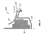
- FIG. 11 shows another alternative blower 800.
- the flange 60 of the blower 800 has a portion 804 that extends locally over the inlet 124 of the cooling air path 132 to reduce ingestion of water in the cooling air path.
- This portion 804 extends a distance D farther than in other embodiments.
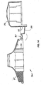
- FIGS. 12 and 13 show another alternative blower 900.
- the flange 60 of the blower 900 has an air scoop 904 adjacent the inlet 124 of the cooling air path.
- the scoop 904 will take advantage of the movement of the air and direct the air into the cooling air path to provide adequate air flow.
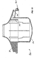
- FIGS. 14 and 15 partially illustrate another alternative blower 960.
- the motor housing 50 including the cover 106
- the cover 106 is integral with the flange 60.
- the cover 106 is formed integrally with the flange 60, including the cylindrical portion 102, such as by injection molding.
- the cover 106 is connected to the flange 60 by a living hinge 964, and the cover is movable relative to the cylindrical portion 102 between an open position ( FIG. 14 ) and a closed position ( FIG. 15 ).
- the flange 60 is formed or molded with the cover 106 in its open position, which facilitates the molding process, as will be understood by those skilled in the art.
- the cover is moved to its closed position to enclose the motor 30 in the motor housing.
- a suitable fastening means such as a snap-fit arrangement (not shown) between the cover 106 and the cylindrical portion 102, can be used to secure the cover in its closed position.
- the cover 106 includes the axial portion 162 and the angled portion 166
Landscapes
- Engineering & Computer Science (AREA)
- Mechanical Engineering (AREA)
- Physics & Mathematics (AREA)
- Thermal Sciences (AREA)
- General Engineering & Computer Science (AREA)
- Structures Of Non-Positive Displacement Pumps (AREA)
- Motor Or Generator Cooling System (AREA)
- Supercharger (AREA)
- Air-Conditioning For Vehicles (AREA)
Claims (28)
- Radialgebläse (10), das umfasst:einen Radiallüfter (20), der eine Nabe, die für eine Drehung um eine Mittelachse (74) ausgelegt ist, undmehrere Schaufeln (82), die mit der Nabe (70) drehfest gekoppelt sind, enthält;einen Motor, der ein Antriebsende und ein gegenüberliegendes Ende besitzt, wobei der Motor eine Antriebswelle (86), die mit der Nabe (70) des Radiallüfters (20) antriebstechnisch verbunden ist, enthält, wobei sich die Antriebswelle (86) von dem Antriebsende des Motors (30) erstreckt und wobei durch den Motor (30) ein Motorluftströmungsweg verläuft, um den Motor (30) zu kühlen, wobei derMotorluftströmungsweg einen Einlass in der Nähe des gegenüberliegenden Endes des Motors (30) besitzt; undeine Gehäusestruktur, miteinem Gebläsegehäuseabschnitt (40), der wenigstens teilweise einen Raum (90) definiert, in dem der Lüfter (20) im Wesentlichen eingeschlossen ist, wobei der Raum (90) einen Einlass (94) und einen Auslass (98) besitzt;einem Motorgehäuseabschnitt, der den Motor (30) unterstützt;einem Flanschabschnitt (60), der denMotorgehäuseabschnitt an dem Gebläsegehäuseabschnitt (40) wenigstens teilweise unterstützt; undeinem Kühlungsluftweg, der einen direkt mit dem Raum (90) kommunizierenden Einlass (124) und einen mit dem Einlass des Motorluftströmungswegs kommunizierenden Auslass (128) besitzt, dadurch gekennzeichnet, dass der Kühlungsluftweg einen stromaufseitigen Abschnitt (132), der sich von dem Kühlungsluftweg-Einlass axial in Richtung von dem gegenüberliegenden Ende des Motors (30) zu dem Antriebsende des Motors (30) erstreckt, besitzt, wobei der Kühlungsluftweg einen stromabseitigen Abschnitt (152) besitzt, der sich axial in Richtung von dem Antriebsende des Motors (30) zu dem gegenüberliegenden Ende des Motors (30) erstreckt,wobei wenigstens ein Abschnitt des stromabseitigen Abschnitts des Kühlungsluftwegs durch den Flanschabschnitt (60) und den Motorgehäuseabschnitt (50) definiert ist.
- Gebläse (10) nach Anspruch 1, wobei einer oder mehrere der Gehäusestrukturabschnitte getrennt von den anderen Abschnitten ausgebildet sind.
- Gebläse (10) nach Anspruch 1, wobei der Flanschabschnitt (60) eine Oberfläche aufweist, die in einer eng beabstandeten, zugewandten Beziehung mit wenigstens einem Abschnitt der Schaufeln (82) steht.
- Gebläse (10) nach Anspruch 1, wobei wenigstens ein Teil des Motorgehäuseabschnitts (50) von dem Flanschabschnitt (60) getrennt ist.
- Gebläse (10) nach Anspruch 1, wobei der Motorluftströmungsweg einen Auslass in der Nähe des Antriebsende des Motors (30) besitzt, wobei der Flanschabschnitt (60) und die Nabe (70) zwischen sich einen axialen Spalt (78) definieren und wobei die Gehäusestruktur einen zweiten Kühlungsluftweg aufweist, der zwischen dem Auslass des Motorluftströmungswegs und dem axialen Spalt (78) kommuniziert.
- Gebläse (10) nach Anspruch 1, wobei der Motor (30) eine axiale Länge besitzt und wobei sich der stromabseitige Abschnitt (152) des Kühlungsluftwegs im Wesentlichen über die gesamte Länge des Motors (30) erstreckt.
- Gebläse (10) nach Anspruch 1, wobei sich der stromaufseitige Abschnitt (132) des Kühlungsluftwegs außerdem radial einwärts erstreckt.
- Gebläse (10) nach Anspruch 1, wobei die Gehäusestrukturabschnitte einteilig ausgebildet sind.
- Gebläse (10) nach Anspruch 1, wobei der Kühlungsluftweg in der Nähe des Kühlungsluftweg-Einlasses (124) einen Wasservorratsbehälter (304) aufweist.
- Gebläse (10) nach Anspruch 1, wobei der stromaufseitige Abschnitt (132) des Kühlungsluftwegs teilweise durch eine Rampenoberfläche (136) aufweist.
- Gebläse (10) nach Anspruch 10, wobei sich die Rampenoberfläche (136) am Motorgehäuseabschnitt (50) befindet.
- Gebläse (10) nach Anspruch 11, wobei der Motorgehäuseabschnitt (50) zum Teil durch eine Struktur einteilig mit dem Flanschabschnitt (60) und zum Teil durch eine getrennte Abdeckung (106), die sich zum Teil über das gegenüberliegende Ende des Motors (30) erstreckt, gebildet ist und wobei sich die Rampenoberfläche (136) an der Abdeckung (106) befindet.
- Gebläse (10) nach Anspruch 1, wobei der stromaufseitige Abschnitt (132) des Kühlungsluftwegs eine erhöhte Sperre (148) aufweist, der der stromabseitigen Wasserströmung in dem Kühlungsluftweg einen Widerstand entgegensetzt.
- Gebläse (10) nach Anspruch 1, wobei der stromaufseitige Abschnitt (132) des Kühlungsluftwegs eine Wand (144) aufweist, die sich im Allgemeinen axial in Richtung von dem Antriebsende des Motors (30) zu dem gegenüberliegenden Ende des Motors (30) erstreckt und einer stromabseitigen Wasserströmung in dem Kühlungsluftweg einen Widerstand entgegensetzt.
- Gebläse (10) nach Anspruch 14, wobei der stromaufseitige Abschnitt (132) des Kühlungsluftwegs eine erhöhte Sperre (148) aufweist, die einer stromabseitigen Wasserströmung in dem Kühlungsluftweg einen Widerstand entgegensetzt.
- Gebläse (10) nach Anspruch 15, wobei der stromaufseitige Abschnitt (132) des Kühlungsluftwegs zum Teil durch eine Rampenoberfläche (136) definiert ist, wobei sich die Sperre (148) von der Rampenoberfläche (136) nach oben erstreckt und wobei sich die Wand (144) zu einem von der Rampenoberfläche (136) beabstandeten Punkt erstreckt und dort endet.
- Gebläse (10) nach Anspruch 1, wobei sich die Gehäusestruktur lokal über den Einlass (124) des Kühlungsluftwegs erstreckt, um die Aufnahme von Wasser in dem Kühlungsluftweg zu verringern.
- Gebläse (10) nach Anspruch 1, wobei die Gehäusestruktur benachbart zu dem Einlass (124) des Kühlungsluftwegs einen Luftstutzen (904) bildet.
- Gebläse (10) nach Anspruch 1, wobei die Gehäusestruktur eine Oberfläche aufweist, die sich im Allgemeinen parallel zu der Achse (74) erstreckt, und wobei der Kühlungsluftweg-Einlass (124) in der Oberfläche vorhanden ist.
- Gebläse (10) nach Anspruch 1, wobei der stromaufseitige Abschnitt (132) des Kühlungsluftwegs eine Labyrinthstruktur aufweist, die einer stromabseitigen Wasserströmung in dem Kühlungsluftweg einen Widerstand entgegensetzt.
- Gebläse (10) nach Anspruch 1, wobei dann, wenn die Achse (74) vertikal ist, der stromaufseitige Abschnitt (132) des Kühlungsluftwegs einen unteren Punkt in der Nähe des Einlasses und einen oberen Punkt benachbart zu dem stromabseitigen Ende des stromaufseitigen Abschnitts (132) besitzt und wobei eine Linie von dem unteren Punkt zu dem oberen Punkt einen Winkel in Bezug auf die Horizontale definiert, der größer als etwa zehn Grad ist.
- Gebläse (10) nach Anspruch 1, wobei dann, wenn die Achse (74) vertikal ist, der stromaufseitige Abschnitt (132) des Kühlungsluftwegs einen unteren Punkt in der Nähe des Einlasses und einen oberen Punkt in der Nähe des stromabseitigen Endes des stromaufseitigen Abschnitts (132) besitzt und wobei eine Linie von dem unteren Punkt zu dem oberen Punkt einen Winkel in Bezug auf die Horizontale definiert, der größer als etwa fünfundzwanzig Grad ist.
- Gebläse (10) nach Anspruch 1, wobei der
Motorgehäuseabschnitt (50) zum Teil durch eine Struktur einteilig mit dem Flanschabschnitt (60) und zum Teil durch eine getrennte Abdeckung (106), die sich zum Teil über das gegenüberliegende Ende des Motors (30) erstreckt, gebildet ist und wobei der Kühlungsluftweg durch den Flanschabschnitt (60) und durch die getrennte Abdeckung (106) definiert ist. - Gebläse (10) nach Anspruch 1, wobei der Motorgehäuseabschnitt (50) einteilig mit dem Flanschabschnitt (60) ausgebildet ist und eine Abdeckung aufweist, die sich über das gegenüberliegende Ende des Motors (30) erstreckt, und wobei der Kühlungsluftweg durch den Flanschabschnitt (60) definiert ist.
- Gebläse (10) nach Anspruch 24, wobei der Flanschabschnitt (60) einen zylindrischen Abschnitt, der den Motor (30) teilweise umgibt, aufweist und wobei die Abdeckung einteilig mit dem zylindrischen Abschnitt ausgebildet ist und mit dem zylindrischen Abschnitt durch ein Überbauscharnier verbunden ist, so dass die Abdeckung relativ zu dem zylindrischen Abschnitt zwischen einer geöffneten und einer geschlossenen Position beweglich ist.
- Gebläse (10) nach Anspruch 1, wobei der stromabseitige Abschnitt (152) des Kühlungsluftwegs zu dem stromaufseitigen Abschnitt (132) benachbart ist, wobei sich kein Abschnitt des stromabseitigen Abschnitts (152) des Kühlungsluftwegs in einer radialen Richtung erstreckt und wobei sich der stromaufseitige Abschnitt (132) und der stromabseitige Abschnitt (152) des Kühlungsluftwegs unter den Schaufeln (82) des Radiallüfters (20) befinden.
- Gebläse (10) nach Anspruch 1, wobei der Flanschabschnitt (60) eine glockenförmige Oberfläche (110) aufweist, die zu den Schaufeln (82) in einer zugewandten Beziehung steht.
- Verfahren zum Montieren eines Radialgebläses (10) in einem Fahrzeug, wobei das Verfahren umfasst:Vorsehen eines Radialgebläses (10), das enthält:einen Radiallüfter (20) mit einer Nabe (70), die für eine Drehung um eine Mittelachse (74) ausgelegt ist, und mehreren Schaufeln (82), die für eine Drehung mit der Nabe (70) gekoppelt sind;einen Motor (30) mit einem Antriebsende und einem gegenüberliegenden Ende, wobei der Motor (30) eine Antriebswelle (86), die mit der Nabe (70) des Radiallüfters (20) antriebstechnisch verbunden ist, enthält, wobei sich die Antriebswelle (86) von dem Antriebsende des Motors (30) erstreckt und wobei durch den Motor (30) ein Luftströmungsweg zum Kühlen des Motors (30) verläuft, wobei der Luftströmungsweg einen Einlass in der Nähe des gegenüberliegenden Endes des Motors (30) besitzt; undeine Gehäusestruktur, miteinem Gebläsegehäuseabschnitt (40), der wenigstens teilweise einen Raum (90) definiert, in dem der Lüfter (20) im Wesentlichen umschlossen ist, wobei der Raum (90) einen Einlass (94) und einen Auslass (98) besitzt;einem Motorgehäuseabschnitt (50), der den Motor (30) unterstützt;einem Flanschabschnitt (60), der den Motorgehäuseabschnitt (50) am Gebläsegehäuseabschnitt (40) wenigstens teilweise unterstützt, und dadurch gekennzeichnet, dassein Kühlungsluftweg vorgesehen ist, der einen Einlass (124), der direkt mit dem Raum (90) kommuniziert, und einen Auslass (128), der mit dem Einlass des Motorluftströmungswegs kommuniziert, umfasst, wobei der Kühlungsluftweg ein stromaufseitiges Ende (132) aufweist, das sich von dem Kühlungsluftweg-Einlass axial in Richtung von dem gegenüberliegenden Ende des Motors (30) zu dem Antriebsende des Motors (30) erstreckt, und der Kühlungsluftweg einen stromabseitigen Abschnitt (152) aufweist, der sich axial in Richtung von dem Antriebsende des Motors (30) zu dem gegenüberliegenden Ende des Motors (30) erstreckt,wobei wenigstens ein Abschnitt des stromabseitigen Abschnitts des Kühlungsluftwegs durch den Flanschabschnitt (60) und den Motorgehäuseabschnitt definiert ist, undMontieren des Gebläses (10) in einem Fahrzeug, derart, dass sich die Mittelachse (74) weder vertikal noch horizontal erstreckt, und derart, dass der Einlass (124) des Kühlungsluftwegs im Wesentlichen direkt unter der Achse (74) vorhanden ist.
Applications Claiming Priority (2)
| Application Number | Priority Date | Filing Date | Title |
|---|---|---|---|
| US11/345,478 US7699587B2 (en) | 2006-02-01 | 2006-02-01 | Cooling channel for automotive HVAC blower assembly |
| PCT/US2007/060439 WO2007089964A1 (en) | 2006-02-01 | 2007-01-12 | Cooling channel for automotive hvac blower assembly |
Publications (2)
| Publication Number | Publication Date |
|---|---|
| EP1993864A1 EP1993864A1 (de) | 2008-11-26 |
| EP1993864B1 true EP1993864B1 (de) | 2011-03-16 |
Family
ID=38057585
Family Applications (1)
| Application Number | Title | Priority Date | Filing Date |
|---|---|---|---|
| EP07717277A Not-in-force EP1993864B1 (de) | 2006-02-01 | 2007-01-12 | Kühlkanal für eine hlk-gebläseanordnung für fahrzeuge |
Country Status (10)
| Country | Link |
|---|---|
| US (1) | US7699587B2 (de) |
| EP (1) | EP1993864B1 (de) |
| JP (1) | JP5237118B2 (de) |
| KR (1) | KR101040844B1 (de) |
| CN (1) | CN101378922B (de) |
| AT (1) | ATE501877T1 (de) |
| BR (1) | BRPI0706797A2 (de) |
| DE (1) | DE602007013186D1 (de) |
| EA (1) | EA014033B1 (de) |
| WO (1) | WO2007089964A1 (de) |
Cited By (1)
| Publication number | Priority date | Publication date | Assignee | Title |
|---|---|---|---|---|
| WO2023144060A1 (de) * | 2022-01-26 | 2023-08-03 | BSH Hausgeräte GmbH | Ventilator für dunstabzugsvorrichtung und dunstabzugsvorrichtung |
Families Citing this family (28)
| Publication number | Priority date | Publication date | Assignee | Title |
|---|---|---|---|---|
| FR2899654B1 (fr) * | 2006-04-10 | 2008-07-04 | Valeo Systemes Thermiques | Canal de refroidissement pour un moteur de ventilateur d'un systeme de ventilation, chauffage et/ou de climatisation |
| US8292572B2 (en) * | 2008-01-15 | 2012-10-23 | GM Global Technology Operations LLC | Blower motor flange diverter |
| FR2944394B1 (fr) * | 2009-04-08 | 2015-11-13 | Valeo Systemes Thermiques | Support moteur pour un moteur d'entrainement d'un groupe moto-ventilateur d'un appareil de chauffage, de ventilation et/ou de climatisation, d'un vehicule automobile |
| DE102009028196A1 (de) * | 2009-08-04 | 2011-02-10 | Robert Bosch Gmbh | Luftspulenwicklung für HVAC-Gebläse |
| JP5501015B2 (ja) * | 2010-02-08 | 2014-05-21 | 山洋電気株式会社 | 電動ファン |
| DE102010002658A1 (de) | 2010-03-08 | 2011-09-08 | Robert Bosch Gmbh | Gebläsemodul |
| DE102010012910B4 (de) * | 2010-03-15 | 2021-12-30 | Valeo Klimasysteme Gmbh | Gebläsemotorkühlung |
| DE102010031303A1 (de) * | 2010-07-14 | 2012-01-19 | Robert Bosch Gmbh | Gebläsemodul |
| JP5556689B2 (ja) * | 2011-02-14 | 2014-07-23 | 株式会社デンソー | 送風機ユニット |
| DE102011105604B4 (de) | 2011-06-27 | 2023-03-16 | Valeo Klimasysteme Gmbh | Gebläsevorrichtung |
| JP5888494B2 (ja) * | 2011-12-15 | 2016-03-22 | 日本電産株式会社 | 遠心ファン装置 |
| DE102011090066A1 (de) * | 2011-12-29 | 2013-07-04 | Robert Bosch Gmbh | Lüftermodul |
| US9121638B2 (en) | 2012-03-26 | 2015-09-01 | Dri-Eaz Products, Inc. | Surface dryers producing uniform exit velocity profiles, and associated systems and methods |
| US9989066B2 (en) | 2013-03-14 | 2018-06-05 | Mahle International Gmbh | Low power and low noise fan-scroll with multiple split incoming air-streams |
| CN103291661B (zh) * | 2013-06-17 | 2016-01-06 | 上海贝洱热系统有限公司 | 降噪汽车空调鼓风机进口防风环装置 |
| USD761950S1 (en) | 2013-07-10 | 2016-07-19 | Dri-Eaz Products, Inc. | Air dryer |
| JP6111914B2 (ja) * | 2013-07-11 | 2017-04-12 | 株式会社デンソー | 送風機 |
| CN104235955B (zh) * | 2014-09-11 | 2017-01-25 | 美的集团武汉制冷设备有限公司 | 空调室内机及空调 |
| US20160208815A1 (en) * | 2015-01-20 | 2016-07-21 | Ford Global Technologies, Llc | Blower assembly for a vehicle |
| JP6380222B2 (ja) * | 2015-04-28 | 2018-08-29 | 株式会社デンソー | 車両用空調装置 |
| FR3043180B1 (fr) * | 2015-10-29 | 2017-11-24 | Valeo Systemes Thermiques | Ensemble support moteur et installation de chauffage, de ventilation et/ou de climatisation pour vehicule automobile correspondante |
| JP6722013B2 (ja) * | 2016-03-22 | 2020-07-15 | 株式会社日本クライメイトシステムズ | 車両空調用送風装置 |
| CN105650842B (zh) * | 2016-03-28 | 2019-04-30 | 广东美的制冷设备有限公司 | 送风部件和空调室内机 |
| JP6873622B2 (ja) * | 2016-07-15 | 2021-05-19 | 三菱重工サーマルシステムズ株式会社 | 送風装置、車両用空気調和装置 |
| WO2018123111A1 (ja) * | 2016-12-27 | 2018-07-05 | 株式会社デンソー | 空調装置 |
| FR3069586B1 (fr) * | 2017-07-26 | 2021-01-01 | Valeo Systemes Thermiques | Pulseur d'air pour vehicule automobile |
| US11236759B2 (en) | 2018-10-29 | 2022-02-01 | Legend Brands, Inc. | Contoured fan blades and associated systems and methods |
| DE102024113614A1 (de) * | 2024-05-15 | 2025-11-20 | Bayerische Motoren Werke Aktiengesellschaft | Modul für eine Klimaanlage eines Kraftfahrzeugs sowie Kraftfahrzeug |
Family Cites Families (34)
| Publication number | Priority date | Publication date | Assignee | Title |
|---|---|---|---|---|
| US3878809A (en) | 1974-02-14 | 1975-04-22 | Morton Ray | Air-cooled electric outboard motor |
| SE403541B (sv) | 1976-10-06 | 1978-08-21 | Skf Ind Trading & Dev | Elmotor som vid den ena axiella endan er ansluten till ett underlago t ex en diskmaskin |
| US4186317A (en) | 1976-10-07 | 1980-01-29 | Sisk Hollis D | Endplate with cast-in baffle |
| JPS6177512A (ja) | 1984-09-25 | 1986-04-21 | Hitachi Ltd | 自動車用ブロア装置 |
| JPS61143212A (ja) * | 1984-12-17 | 1986-06-30 | Nissan Motor Co Ltd | 自動車用ブロア装置 |
| US4958988A (en) * | 1985-09-26 | 1990-09-25 | Ormat Turbines, Ltd. | Motor driven pump for pumping viscous solutions |
| JPS6336100A (ja) * | 1986-07-30 | 1988-02-16 | Nippon Radiator Co Ltd | モ−タ冷却装置とその製造方法 |
| US4856971A (en) | 1988-09-16 | 1989-08-15 | Koble Jr Robert L | Evaporative cooler pump apparatus |
| JPH02151519A (ja) | 1988-12-02 | 1990-06-11 | Hitachi Ltd | 車両用空調機の送風装置 |
| JPH04113142A (ja) * | 1990-09-03 | 1992-04-14 | Deitsukusu Kk | ダクト用換気装置 |
| DE4041424C2 (de) | 1990-12-21 | 1995-03-30 | Lescha Maschf Gmbh | Mischer |
| DE4143383C2 (de) * | 1991-07-03 | 1995-03-30 | Licentia Gmbh | Axialgebläse, insbesondere zur Kühlung eines dem Kühler eines Fahrzeugs vorgeordneten Kondensators einer Klimaanlage |
| JP2755317B2 (ja) * | 1991-11-13 | 1998-05-20 | 株式会社デンソー | 送風機 |
| DE4220669C1 (en) | 1992-06-24 | 1993-07-22 | Mercedes-Benz Aktiengesellschaft, 7000 Stuttgart, De | Radial fan esp. for air conditioning and ventilation inside vehicles - has electric motor driving fan impeller with both housed in volute casing having axial suction opening and pressure volute ending in tangential air outlet opening. |
| JP3545846B2 (ja) | 1995-06-14 | 2004-07-21 | 株式会社ミツバ | ファンモータの水抜き構造 |
| JP3426151B2 (ja) * | 1998-03-16 | 2003-07-14 | アスモ株式会社 | ブラシレスモータ |
| DE19909507C1 (de) * | 1999-03-04 | 2000-11-16 | Temic Auto Electr Motors Gmbh | Radialgebläse, insbesondere für Heizungs- und Klimaanlagen |
| JP4421083B2 (ja) * | 2000-06-12 | 2010-02-24 | アスモ株式会社 | ブラシレスモータ |
| JP4185654B2 (ja) * | 2000-08-04 | 2008-11-26 | カルソニックカンセイ株式会社 | 遠心式の多翼送風機 |
| US6755615B2 (en) * | 2000-12-04 | 2004-06-29 | Robert Bosch Corporation | High efficiency one-piece centrifugal blower |
| US6563240B2 (en) | 2001-04-24 | 2003-05-13 | A. O. Smith Corporation | Electric motor having a rain baffle |
| US6703730B2 (en) | 2001-05-24 | 2004-03-09 | Asmo Co., Ltd. | Electric motor cooling having air-communication restrain between intake duct and exhaust duct, and having cooling fan received in yoke |
| US6717299B2 (en) | 2001-10-30 | 2004-04-06 | Robert Bosch Corporation | Isolation system for a motor |
| GB0202835D0 (en) * | 2002-02-07 | 2002-03-27 | Johnson Electric Sa | Blower motor |
| KR100651684B1 (ko) * | 2002-05-10 | 2006-11-30 | 한라공조주식회사 | 송풍기 모우터의 냉각장치 |
| US6802699B2 (en) * | 2002-06-06 | 2004-10-12 | Calsonic Kansei Corporation | Motor mounting structure |
| JP2004092594A (ja) * | 2002-09-03 | 2004-03-25 | Denso Corp | 遠心式送風機および車両用空調装置 |
| US6831435B2 (en) * | 2002-10-02 | 2004-12-14 | Asmo Co., Ltd. | Vehicle blower motor device and holder for blower motor device |
| JP2004237838A (ja) * | 2003-02-05 | 2004-08-26 | Denso Corp | ブロワ装置用ケーシング |
| DE10313054B4 (de) * | 2003-03-24 | 2012-10-04 | Motoren Ventilatoren Landshut Gmbh | Radialgebläse |
| JP2004343914A (ja) * | 2003-05-16 | 2004-12-02 | Matsushita Electric Ind Co Ltd | 電動送風機 |
| FR2856852B1 (fr) | 2003-06-27 | 2006-09-29 | Asmo Co Ltd | Ensemble moteur pour climatiseur pour vehicules |
| US6831382B1 (en) | 2004-03-17 | 2004-12-14 | Emerson Electric Co. | Cover for electric motor |
| JP4337669B2 (ja) * | 2004-07-13 | 2009-09-30 | 株式会社デンソー | 車両用電動送風ファン装置 |
-
2006
- 2006-02-01 US US11/345,478 patent/US7699587B2/en not_active Expired - Fee Related
-
2007
- 2007-01-12 AT AT07717277T patent/ATE501877T1/de not_active IP Right Cessation
- 2007-01-12 DE DE602007013186T patent/DE602007013186D1/de active Active
- 2007-01-12 WO PCT/US2007/060439 patent/WO2007089964A1/en not_active Ceased
- 2007-01-12 BR BRPI0706797-6A patent/BRPI0706797A2/pt not_active IP Right Cessation
- 2007-01-12 EA EA200801787A patent/EA014033B1/ru not_active IP Right Cessation
- 2007-01-12 EP EP07717277A patent/EP1993864B1/de not_active Not-in-force
- 2007-01-12 JP JP2008553434A patent/JP5237118B2/ja active Active
- 2007-01-12 KR KR1020087021191A patent/KR101040844B1/ko not_active Expired - Fee Related
- 2007-01-12 CN CN2007800043151A patent/CN101378922B/zh not_active Expired - Fee Related
Cited By (1)
| Publication number | Priority date | Publication date | Assignee | Title |
|---|---|---|---|---|
| WO2023144060A1 (de) * | 2022-01-26 | 2023-08-03 | BSH Hausgeräte GmbH | Ventilator für dunstabzugsvorrichtung und dunstabzugsvorrichtung |
Also Published As
| Publication number | Publication date |
|---|---|
| CN101378922B (zh) | 2011-12-14 |
| KR20080098050A (ko) | 2008-11-06 |
| BRPI0706797A2 (pt) | 2011-07-26 |
| CN101378922A (zh) | 2009-03-04 |
| EA200801787A1 (ru) | 2008-12-30 |
| JP5237118B2 (ja) | 2013-07-17 |
| EP1993864A1 (de) | 2008-11-26 |
| DE602007013186D1 (de) | 2011-04-28 |
| US7699587B2 (en) | 2010-04-20 |
| US20070177996A1 (en) | 2007-08-02 |
| WO2007089964A1 (en) | 2007-08-09 |
| ATE501877T1 (de) | 2011-04-15 |
| EA014033B1 (ru) | 2010-08-30 |
| JP2009525434A (ja) | 2009-07-09 |
| KR101040844B1 (ko) | 2011-06-14 |
Similar Documents
| Publication | Publication Date | Title |
|---|---|---|
| US7699587B2 (en) | Cooling channel for automotive HVAC blower assembly | |
| JP5012736B2 (ja) | 遠心式送風機 | |
| JP4337669B2 (ja) | 車両用電動送風ファン装置 | |
| CN1182643C (zh) | 带轴向入口的通风用鼓风机叶轮 | |
| US6893218B2 (en) | Centrifugal blower unit | |
| JP2009525434A5 (de) | ||
| KR20120123440A (ko) | 원심 송풍기 | |
| CN102971541A (zh) | 风扇组件的电机环和防溅罩装置 | |
| JP2006200525A (ja) | 遠心式多翼送風機 | |
| CN106080095A (zh) | 尤其用于机动车辆的通风单元 | |
| US8167550B2 (en) | Blower unit | |
| US10655636B2 (en) | Centrifugal air blower | |
| JP5217626B2 (ja) | 車両用空調装置のブロワユニット | |
| JP4116359B2 (ja) | 遠心送風機 | |
| CN102562627B (zh) | 风扇装置 | |
| JP7716234B2 (ja) | 車両空調装置用送風機 | |
| JP2011230589A (ja) | 車両用空調装置の送風ユニット | |
| JP2011252478A (ja) | 多翼遠心ファンおよびそれを用いた車両用空調装置 | |
| JP3785758B2 (ja) | 送風ユニット | |
| US8292572B2 (en) | Blower motor flange diverter | |
| JP2004190535A (ja) | 遠心式送風機及び空調装置用の送風機 | |
| JP6340225B2 (ja) | 遠心ファン | |
| US7473078B2 (en) | Centrifugal blower | |
| KR102121971B1 (ko) | 차량의 공기조화장치용 인테이크 시스템 | |
| JP4862809B2 (ja) | 遠心式送風機 |
Legal Events
| Date | Code | Title | Description |
|---|---|---|---|
| PUAI | Public reference made under article 153(3) epc to a published international application that has entered the european phase |
Free format text: ORIGINAL CODE: 0009012 |
|
| 17P | Request for examination filed |
Effective date: 20080901 |
|
| AK | Designated contracting states |
Kind code of ref document: A1 Designated state(s): AT BE BG CH CY CZ DE DK EE ES FI FR GB GR HU IE IS IT LI LT LU LV MC NL PL PT RO SE SI SK TR |
|
| 17Q | First examination report despatched |
Effective date: 20090216 |
|
| GRAP | Despatch of communication of intention to grant a patent |
Free format text: ORIGINAL CODE: EPIDOSNIGR1 |
|
| DAX | Request for extension of the european patent (deleted) | ||
| GRAS | Grant fee paid |
Free format text: ORIGINAL CODE: EPIDOSNIGR3 |
|
| GRAA | (expected) grant |
Free format text: ORIGINAL CODE: 0009210 |
|
| AK | Designated contracting states |
Kind code of ref document: B1 Designated state(s): AT BE BG CH CY CZ DE DK EE ES FI FR GB GR HU IE IS IT LI LT LU LV MC NL PL PT RO SE SI SK TR |
|
| REG | Reference to a national code |
Ref country code: GB Ref legal event code: FG4D |
|
| REG | Reference to a national code |
Ref country code: CH Ref legal event code: EP |
|
| REG | Reference to a national code |
Ref country code: IE Ref legal event code: FG4D |
|
| REF | Corresponds to: |
Ref document number: 602007013186 Country of ref document: DE Date of ref document: 20110428 Kind code of ref document: P |
|
| REG | Reference to a national code |
Ref country code: DE Ref legal event code: R096 Ref document number: 602007013186 Country of ref document: DE Effective date: 20110428 |
|
| REG | Reference to a national code |
Ref country code: NL Ref legal event code: VDEP Effective date: 20110316 |
|
| PG25 | Lapsed in a contracting state [announced via postgrant information from national office to epo] |
Ref country code: SE Free format text: LAPSE BECAUSE OF FAILURE TO SUBMIT A TRANSLATION OF THE DESCRIPTION OR TO PAY THE FEE WITHIN THE PRESCRIBED TIME-LIMIT Effective date: 20110316 Ref country code: LV Free format text: LAPSE BECAUSE OF FAILURE TO SUBMIT A TRANSLATION OF THE DESCRIPTION OR TO PAY THE FEE WITHIN THE PRESCRIBED TIME-LIMIT Effective date: 20110316 Ref country code: ES Free format text: LAPSE BECAUSE OF FAILURE TO SUBMIT A TRANSLATION OF THE DESCRIPTION OR TO PAY THE FEE WITHIN THE PRESCRIBED TIME-LIMIT Effective date: 20110627 Ref country code: LT Free format text: LAPSE BECAUSE OF FAILURE TO SUBMIT A TRANSLATION OF THE DESCRIPTION OR TO PAY THE FEE WITHIN THE PRESCRIBED TIME-LIMIT Effective date: 20110316 Ref country code: GR Free format text: LAPSE BECAUSE OF FAILURE TO SUBMIT A TRANSLATION OF THE DESCRIPTION OR TO PAY THE FEE WITHIN THE PRESCRIBED TIME-LIMIT Effective date: 20110617 |
|
| LTIE | Lt: invalidation of european patent or patent extension |
Effective date: 20110316 |
|
| PG25 | Lapsed in a contracting state [announced via postgrant information from national office to epo] |
Ref country code: FI Free format text: LAPSE BECAUSE OF FAILURE TO SUBMIT A TRANSLATION OF THE DESCRIPTION OR TO PAY THE FEE WITHIN THE PRESCRIBED TIME-LIMIT Effective date: 20110316 Ref country code: AT Free format text: LAPSE BECAUSE OF FAILURE TO SUBMIT A TRANSLATION OF THE DESCRIPTION OR TO PAY THE FEE WITHIN THE PRESCRIBED TIME-LIMIT Effective date: 20110316 Ref country code: BG Free format text: LAPSE BECAUSE OF FAILURE TO SUBMIT A TRANSLATION OF THE DESCRIPTION OR TO PAY THE FEE WITHIN THE PRESCRIBED TIME-LIMIT Effective date: 20110616 Ref country code: CY Free format text: LAPSE BECAUSE OF FAILURE TO SUBMIT A TRANSLATION OF THE DESCRIPTION OR TO PAY THE FEE WITHIN THE PRESCRIBED TIME-LIMIT Effective date: 20110316 Ref country code: SI Free format text: LAPSE BECAUSE OF FAILURE TO SUBMIT A TRANSLATION OF THE DESCRIPTION OR TO PAY THE FEE WITHIN THE PRESCRIBED TIME-LIMIT Effective date: 20110316 |
|
| PG25 | Lapsed in a contracting state [announced via postgrant information from national office to epo] |
Ref country code: BE Free format text: LAPSE BECAUSE OF FAILURE TO SUBMIT A TRANSLATION OF THE DESCRIPTION OR TO PAY THE FEE WITHIN THE PRESCRIBED TIME-LIMIT Effective date: 20110316 |
|
| PG25 | Lapsed in a contracting state [announced via postgrant information from national office to epo] |
Ref country code: PT Free format text: LAPSE BECAUSE OF FAILURE TO SUBMIT A TRANSLATION OF THE DESCRIPTION OR TO PAY THE FEE WITHIN THE PRESCRIBED TIME-LIMIT Effective date: 20110718 Ref country code: EE Free format text: LAPSE BECAUSE OF FAILURE TO SUBMIT A TRANSLATION OF THE DESCRIPTION OR TO PAY THE FEE WITHIN THE PRESCRIBED TIME-LIMIT Effective date: 20110316 |
|
| PG25 | Lapsed in a contracting state [announced via postgrant information from national office to epo] |
Ref country code: RO Free format text: LAPSE BECAUSE OF FAILURE TO SUBMIT A TRANSLATION OF THE DESCRIPTION OR TO PAY THE FEE WITHIN THE PRESCRIBED TIME-LIMIT Effective date: 20110316 Ref country code: SK Free format text: LAPSE BECAUSE OF FAILURE TO SUBMIT A TRANSLATION OF THE DESCRIPTION OR TO PAY THE FEE WITHIN THE PRESCRIBED TIME-LIMIT Effective date: 20110316 Ref country code: CZ Free format text: LAPSE BECAUSE OF FAILURE TO SUBMIT A TRANSLATION OF THE DESCRIPTION OR TO PAY THE FEE WITHIN THE PRESCRIBED TIME-LIMIT Effective date: 20110316 Ref country code: IS Free format text: LAPSE BECAUSE OF FAILURE TO SUBMIT A TRANSLATION OF THE DESCRIPTION OR TO PAY THE FEE WITHIN THE PRESCRIBED TIME-LIMIT Effective date: 20110716 |
|
| PG25 | Lapsed in a contracting state [announced via postgrant information from national office to epo] |
Ref country code: NL Free format text: LAPSE BECAUSE OF FAILURE TO SUBMIT A TRANSLATION OF THE DESCRIPTION OR TO PAY THE FEE WITHIN THE PRESCRIBED TIME-LIMIT Effective date: 20110316 |
|
| PLBE | No opposition filed within time limit |
Free format text: ORIGINAL CODE: 0009261 |
|
| STAA | Information on the status of an ep patent application or granted ep patent |
Free format text: STATUS: NO OPPOSITION FILED WITHIN TIME LIMIT |
|
| 26N | No opposition filed |
Effective date: 20111219 |
|
| PG25 | Lapsed in a contracting state [announced via postgrant information from national office to epo] |
Ref country code: DK Free format text: LAPSE BECAUSE OF FAILURE TO SUBMIT A TRANSLATION OF THE DESCRIPTION OR TO PAY THE FEE WITHIN THE PRESCRIBED TIME-LIMIT Effective date: 20110316 Ref country code: PL Free format text: LAPSE BECAUSE OF FAILURE TO SUBMIT A TRANSLATION OF THE DESCRIPTION OR TO PAY THE FEE WITHIN THE PRESCRIBED TIME-LIMIT Effective date: 20110316 |
|
| REG | Reference to a national code |
Ref country code: DE Ref legal event code: R097 Ref document number: 602007013186 Country of ref document: DE Effective date: 20111219 |
|
| PG25 | Lapsed in a contracting state [announced via postgrant information from national office to epo] |
Ref country code: IT Free format text: LAPSE BECAUSE OF FAILURE TO SUBMIT A TRANSLATION OF THE DESCRIPTION OR TO PAY THE FEE WITHIN THE PRESCRIBED TIME-LIMIT Effective date: 20110316 |
|
| PG25 | Lapsed in a contracting state [announced via postgrant information from national office to epo] |
Ref country code: MC Free format text: LAPSE BECAUSE OF NON-PAYMENT OF DUE FEES Effective date: 20120131 |
|
| REG | Reference to a national code |
Ref country code: CH Ref legal event code: PL |
|
| REG | Reference to a national code |
Ref country code: IE Ref legal event code: MM4A |
|
| PG25 | Lapsed in a contracting state [announced via postgrant information from national office to epo] |
Ref country code: LI Free format text: LAPSE BECAUSE OF NON-PAYMENT OF DUE FEES Effective date: 20120131 Ref country code: CH Free format text: LAPSE BECAUSE OF NON-PAYMENT OF DUE FEES Effective date: 20120131 |
|
| PG25 | Lapsed in a contracting state [announced via postgrant information from national office to epo] |
Ref country code: IE Free format text: LAPSE BECAUSE OF NON-PAYMENT OF DUE FEES Effective date: 20120112 |
|
| PG25 | Lapsed in a contracting state [announced via postgrant information from national office to epo] |
Ref country code: TR Free format text: LAPSE BECAUSE OF FAILURE TO SUBMIT A TRANSLATION OF THE DESCRIPTION OR TO PAY THE FEE WITHIN THE PRESCRIBED TIME-LIMIT Effective date: 20110316 |
|
| PG25 | Lapsed in a contracting state [announced via postgrant information from national office to epo] |
Ref country code: LU Free format text: LAPSE BECAUSE OF NON-PAYMENT OF DUE FEES Effective date: 20120112 |
|
| PG25 | Lapsed in a contracting state [announced via postgrant information from national office to epo] |
Ref country code: HU Free format text: LAPSE BECAUSE OF FAILURE TO SUBMIT A TRANSLATION OF THE DESCRIPTION OR TO PAY THE FEE WITHIN THE PRESCRIBED TIME-LIMIT Effective date: 20070112 |
|
| REG | Reference to a national code |
Ref country code: FR Ref legal event code: PLFP Year of fee payment: 10 |
|
| PGFP | Annual fee paid to national office [announced via postgrant information from national office to epo] |
Ref country code: GB Payment date: 20160122 Year of fee payment: 10 Ref country code: FR Payment date: 20160121 Year of fee payment: 10 |
|
| GBPC | Gb: european patent ceased through non-payment of renewal fee |
Effective date: 20170112 |
|
| REG | Reference to a national code |
Ref country code: FR Ref legal event code: ST Effective date: 20170929 |
|
| PG25 | Lapsed in a contracting state [announced via postgrant information from national office to epo] |
Ref country code: FR Free format text: LAPSE BECAUSE OF NON-PAYMENT OF DUE FEES Effective date: 20170131 |
|
| PG25 | Lapsed in a contracting state [announced via postgrant information from national office to epo] |
Ref country code: GB Free format text: LAPSE BECAUSE OF NON-PAYMENT OF DUE FEES Effective date: 20170112 |
|
| PGFP | Annual fee paid to national office [announced via postgrant information from national office to epo] |
Ref country code: DE Payment date: 20190326 Year of fee payment: 13 |
|
| REG | Reference to a national code |
Ref country code: DE Ref legal event code: R119 Ref document number: 602007013186 Country of ref document: DE |
|
| PG25 | Lapsed in a contracting state [announced via postgrant information from national office to epo] |
Ref country code: DE Free format text: LAPSE BECAUSE OF NON-PAYMENT OF DUE FEES Effective date: 20200801 |