EP1995233A2 - Procédé de fabrication de carbonates de diaryle ou d'arylalkyle à partir de carbonates de dialkyle - Google Patents
Procédé de fabrication de carbonates de diaryle ou d'arylalkyle à partir de carbonates de dialkyle Download PDFInfo
- Publication number
- EP1995233A2 EP1995233A2 EP08008796A EP08008796A EP1995233A2 EP 1995233 A2 EP1995233 A2 EP 1995233A2 EP 08008796 A EP08008796 A EP 08008796A EP 08008796 A EP08008796 A EP 08008796A EP 1995233 A2 EP1995233 A2 EP 1995233A2
- Authority
- EP
- European Patent Office
- Prior art keywords
- column
- carbonate
- transesterification
- reaction zone
- condenser
- Prior art date
- Legal status (The legal status is an assumption and is not a legal conclusion. Google has not performed a legal analysis and makes no representation as to the accuracy of the status listed.)
- Withdrawn
Links
Images


Classifications
-
- C—CHEMISTRY; METALLURGY
- C07—ORGANIC CHEMISTRY
- C07C—ACYCLIC OR CARBOCYCLIC COMPOUNDS
- C07C68/00—Preparation of esters of carbonic or haloformic acids
- C07C68/06—Preparation of esters of carbonic or haloformic acids from organic carbonates
-
- B—PERFORMING OPERATIONS; TRANSPORTING
- B01—PHYSICAL OR CHEMICAL PROCESSES OR APPARATUS IN GENERAL
- B01D—SEPARATION
- B01D3/00—Distillation or related exchange processes in which liquids are contacted with gaseous media, e.g. stripping
- B01D3/009—Distillation or related exchange processes in which liquids are contacted with gaseous media, e.g. stripping in combination with chemical reactions
-
- C—CHEMISTRY; METALLURGY
- C07—ORGANIC CHEMISTRY
- C07C—ACYCLIC OR CARBOCYCLIC COMPOUNDS
- C07C68/00—Preparation of esters of carbonic or haloformic acids
- C07C68/08—Purification; Separation; Stabilisation
-
- C—CHEMISTRY; METALLURGY
- C07—ORGANIC CHEMISTRY
- C07C—ACYCLIC OR CARBOCYCLIC COMPOUNDS
- C07C69/00—Esters of carboxylic acids; Esters of carbonic or haloformic acids
- C07C69/96—Esters of carbonic or haloformic acids
-
- Y—GENERAL TAGGING OF NEW TECHNOLOGICAL DEVELOPMENTS; GENERAL TAGGING OF CROSS-SECTIONAL TECHNOLOGIES SPANNING OVER SEVERAL SECTIONS OF THE IPC; TECHNICAL SUBJECTS COVERED BY FORMER USPC CROSS-REFERENCE ART COLLECTIONS [XRACs] AND DIGESTS
- Y02—TECHNOLOGIES OR APPLICATIONS FOR MITIGATION OR ADAPTATION AGAINST CLIMATE CHANGE
- Y02P—CLIMATE CHANGE MITIGATION TECHNOLOGIES IN THE PRODUCTION OR PROCESSING OF GOODS
- Y02P20/00—Technologies relating to chemical industry
- Y02P20/10—Process efficiency
-
- Y—GENERAL TAGGING OF NEW TECHNOLOGICAL DEVELOPMENTS; GENERAL TAGGING OF CROSS-SECTIONAL TECHNOLOGIES SPANNING OVER SEVERAL SECTIONS OF THE IPC; TECHNICAL SUBJECTS COVERED BY FORMER USPC CROSS-REFERENCE ART COLLECTIONS [XRACs] AND DIGESTS
- Y10—TECHNICAL SUBJECTS COVERED BY FORMER USPC
- Y10S—TECHNICAL SUBJECTS COVERED BY FORMER USPC CROSS-REFERENCE ART COLLECTIONS [XRACs] AND DIGESTS
- Y10S203/00—Distillation: processes, separatory
Definitions
- the invention relates to a process for the preparation of diaryl carbonates and / or alkylaryl carbonates from dialkyl carbonates and aromatic hydroxy compounds using at least one reaction column with one or more intermediate condensers to improve the heat integration.
- the transesterification is also preferably carried out continuously in the sense of a countercurrent transesterification in one or more reaction columns.
- EP-A 0 461 274 describes a continuous transesterification process for the preparation of aromatic carbonates in one or more series-connected multistage columns, wherein dialkyl or alkylaryl are reacted with phenols and at the top of the columns the volatile products, namely the reaction alcohols and dialkyl and at the bottom of the columns, the high-boiling products , such as diaryl carbonates are removed.
- special process measures which permit a more advantageous transesterification by adapting the apparatuses and procedures to the specific problems of this transesterification mentioned above are not described.
- the person skilled in the art receives no indication as to whether the column used for transesterification is preferably carried out with or without a reinforcing part.
- the vapor mixture taken off at the top of the column essentially contains the excess used in the reaction Dialkyl carbonate and the corresponding resulting in the reaction of alcohol and the condensation of the mixture is carried out at a temperature which is below the vaporization temperature of the dialkyl carbonate at the pressure present in the reaction, with the result that the heat of condensation compared to the temperature in the reaction zone can be dissipated only at a low temperature level. If the transesterification column is carried out without a reinforcing part, the vapor mixture taken off at the top of the column and thus also the distillate of the column contains not insignificant amounts of the aromatic hydroxy compounds used for the reaction and optionally also heavier components.
- DE-A 42 26 756 describes a two-step process for the preparation of diaryl carbonates in which, in a first step, an aromatic hydroxy compound is reacted with a dialkyl carbonate in a countercurrent transesterification using a countercurrent transesterification column which can be carried out both with and without a reinforcing part.
- the temperature level in the condensation is relatively low, so that the resulting heat of condensation can not be used economically for operating other process sections.
- the distillate additionally contains a high proportion of the aromatic hydroxy compound in addition to the dialkyl carbonate and the alcohol formed upon reaction. This results in the recovery of the dialkyl carbonate to an elevated temperature level in the region of the column bottom, which makes it difficult to supply energy at this point.
- DE-A 42 26 755 describes a process for the preparation of diaryl carbonates in two energetically and materially coupled reaction columns, wherein in the first stage an aromatic hydroxy compounds and a dialkyl carbonate are reacted and the resulting alkylaryl carbonate in the second stage either by transesterification with the aromatic hydroxy compound or by Disproportionation is converted to diaryl carbonate.
- the problem here is, however, that the reaction conditions for the formation of the alkylaryl or diaryl carbonate can not be optimally selected by the material and energetic integration of the process, since these are determined by the present in both steps and almost identical pressure. The method described therefore provides no advantages in terms of energy integration.
- the EP-A 781 760 describes a continuous process for preparing aromatic carbonates by reacting a dialkyl carbonate with an aromatic hydroxy compound in the presence of a catalyst, continuously removing the aromatic carbonate resulting from the reaction, the alcoholic by-products, the dialkyl carbonate and the hydroxy aromatic compound, the dialkyl carbonate and the hydroxy aromatic compound again be attributed to the reaction.
- the method steps described are effective with respect to the reaction in terms of a high space-time yield and the workup in the sense of the most efficient separation sequence, but the process shows no possibilities for an energetic integration of the reaction and work-up steps.
- WO-A 2006/001256 describes a process in which an aromatic hydroxy compound is reacted with a dialkyl carbonate in the presence of a catalyst and a technical device suitable for this purpose. Again, no clues are given for energetic integration.
- WO-A 2004/016577 describes a process for the preparation of aromatic carbonates from dialkyl carbonate and an aromatic hydroxy compound in the presence of a catalyst in a plurality of separate and series reaction zones of a reactor arrangement, wherein the resulting heat of condensation in the condensation of the vapor stream of the last reaction zone for heating the liquid stream introduced into the first reaction zone is used.
- a disadvantage of this method is the complex reactor arrangement.
- the energy integration of this process is in need of improvement.
- the object on which the invention was based was therefore to provide a process for the preparation of aromatic carbonates, ie diaryl and / or alkylaryl carbonates, preferably diaryl carbonates, in which over known processes a Energy integration is possible in an efficient manner or an improved energy integration can be achieved.
- This object has been achieved according to the invention by the appropriate use of one or more intermediate condensers in a process for the preparation of aromatic carbonates, i. Diaryl and / or alkylaryl, from dialkyl carbonates and aromatic hydroxy compounds energy integration can be significantly improved with simple process control.
- Diaryl carbonates prepared in the context of the invention are preferably those of the general formula (I) where R, R 'and R "independently of one another are H, linear or branched, optionally substituted C 1 -C 34 -alkyl, preferably C 1 -C 6 -alkyl, particularly preferably C 1 -C 4 -alkyl, C 1 -C 34 Alkoxy, preferably C 1 -C 6 -alkoxy, more preferably C 1 -C 4 -alkoxy, C 5 -C 34 -cycloalkyl, C 7 -C 34 -alkylaryl, C 6 -C 34 -aryl or a halogen radical represent a chlorine radical and R, R 'and R "may be the same or different on both sides of the formula (I).
- R can also be -COO-R '", where R"' is H, optionally branched C 1 -C 34 -alkyl, preferably C 1 -C 6 -alkyl, particularly preferably C 1 -C 4 -alkyl, C 1 -C 34 -alkoxy, preferably C 1 -C 6 -alkoxy, particularly preferably C 1 -C 4 -alkoxy, C 5 -C 34 -cycloalkyl, C 7 -C 34 Alkylaryl or C 6 -C 34 -aryl.
- R, R 'and R are preferably the same on both sides of the formula (I).
- R, R' and R" are very particularly preferably H.
- Diarylcarbonates of the general formula (I) are, for example: diphenyl carbonate, methylphenylphenyl carbonates and di (methylphenyl) carbonates, also as a mixture, where the position of the methyl group on the phenyl rings may be arbitrary, and dimethylphenyl-phenyl-carbonates and di ( dimethylphenyl) carbonates, also as a mixture, wherein the position of the methyl groups on the phenyl rings may be arbitrary, chlorophenyl-phenyl-carbonates and di (chlorophenyl) carbonates, wherein the position of the methyl group on the phenyl rings may be arbitrary, 4-ethylphenyl phenyl carbonate, di- (4-ethylphenyl) carbonate, 4-n-propylphenyl phenyl carbonate, di- (4-n-propylphenyl) carbonate, 4-iso-propylphenyl phenyl carbonate, di- ( 4-iso-
- Preferred diaryl carbonates are: diphenyl carbonate, 4-tert-butylphenyl phenyl carbonate, di (4-tert-butylphenyl) carbonate, biphenyl-4-yl phenyl carbonate, di (biphenyl-4-yl) carbonate, 4- (1-methyl-1-phenylethyl) -phenyl-phenyl-carbonate and di- [4- (1-methyl-1-phenylethyl) -phenyl] -carbonate.
- diphenyl carbonate is particularly preferred.
- Dialkyl carbonates preferably used in the context of the invention are those of the formula (II) wherein R 1 and R 2 independently of one another are linear or branched, optionally substituted C 1 -C 34 -alkyl, preferably C 1 -C 6 -alkyl, more preferably C 1 -C 4 -alkyl.
- R 1 and R 2 may be the same or different.
- R 1 and R 2 are the same.
- C 1 -C 4 -alkyl is, for example, methyl, ethyl, n-propyl, isopropyl, n-butyl, sec-butyl, tert-butyl, C 1 -C 6 -alkyl, moreover, for example for n-pentyl, 1-methylbutyl, 2-methylbutyl, 3-methylbutyl, neo-pentyl, 1-ethylpropyl, cyclohexyl, cyclopentyl, n-hexyl, 1,1-dimethylpropyl, 1,2-dimethylpropyl, 1-methylpentyl, 2 Methylpentyl, 3-methylpentyl, 4-methylpentyl, 1,1-dimethylbutyl, 1,2-dimethylbutyl, 1,3-dimethylbutyl, 2,2-dimethylbutyl, 2,3-dimethylbutyl, 3,3-di
- Alkylene radicals in the corresponding hydroxyalkyl or aralkyl or alkylaryl radicals are, for example, the alkylene radicals corresponding to the preceding alkyl radicals.
- Aryl represents a carbocyclic aromatic radical having 6 to 34 skeleton carbon atoms.
- aromatic part of an arylalkyl radical also called aralkyl radical
- aryl constituents of more complex groups such as e.g. Arylcarbonyl.
- Arylalkyl or aralkyl each independently a straight-chain, cyclic, branched or unbranched alkyl radical as defined above which is simple, can be substituted by aryl radicals as defined above, multiply or fully.
- Preferred dialkyl carbonates are dimethyl carbonate, diethyl carbonate, di (n-propyl) carbonate, di (iso-propyl) carbonate, di (n-butyl) carbonate, di (sec-butyl) carbonate, di (tert-butyl) carbonate or dihexyl carbonate. Particularly preferred are dimethyl carbonate or diethyl carbonate. Very particular preference is given to dimethyl carbonate.
- suitable aromatic hydroxy compounds are preferably those of the general formula (III) wherein R, R 'and R "independently of one another may have the meaning given for the general formula (I).
- aromatic hydroxy compounds are, for example: phenol, o-, m- or p-cresol, also as a mixture of cresols, dimethylphenol, also as a mixture, wherein the position of the methyl groups on the phenol ring may be arbitrary, e.g.
- Preferred diaryl compounds are phenol, 4-tert-butylphenol, biphenyl-4-ol and 4- (1-methyl-1-phenylethyl) phenol.
- Particularly preferred is phenol.
- Alkylaryl carbonates prepared in the context of the invention are preferably those of the general formula (IV) wherein R, R 'and R "for the general formula (I) and R 1 may have the meaning given for the general formula (II).
- Preferred alkylaryl carbonates are methyl phenyl carbonate, ethyl phenyl carbonate, propyl phenyl carbonate, butyl phenyl carbonate and hexyl phenyl carbonate, methyl (o-cresyl) carbonate, methyl (p-cresyl) carbonate , Ethyl (o-cresyl) carbonate, ethyl (p-cresyl) carbonate, methyl or ethyl (p-chlorophenyl) carbonate.
- Particularly preferred alkylaryl carbonates are methyl phenyl carbonate and ethyl phenyl carbonate. Very particular preference is given to methylphenyl carbonate.
- dialkyl carbonates which are suitable for the process according to the invention and the aromatic hydroxy compounds are known to the person skilled in the art and are commercially available or can be prepared by processes which are likewise known to the person skilled in the art.
- the aromatic hydroxy compound (s) and the dialkyl carbonate (s) are preferably in a molar ratio of from 1: 0.1 to 1:10, more preferably from 1: 0.2 to 1: 5, most preferably from 1: 0.5 to 1: 3 used.
- the stated molar ratio does not take into account the recycling of aromatic hydroxy compound or dialkyl carbonate into the transesterification column via one or more top condenser (s) (see under (b)) or one or more optional bottom evaporators.
- the process according to the invention is carried out in a transesterification column.
- the liquid stream taken off at the bottom of this transesterification column can, if appropriate after concentration, be subjected to disproportionation, further transesterification and / or purification in one or more further steps.
- individual or all such further steps can take place in one or more further columns.
- transesterification column or optionally second or further column (s) known to those skilled in columns come into question.
- these are, for example, distillation or rectification columns, preferably reactive distillation columns or reactive rectification columns.
- the transesterification column contains at least one enrichment section in the upper part of the column and at least one reaction zone below the reinforcement section, which has at least two sections, wherein at least one reinforcement section of the transesterification column is equipped with at least one intermediate condenser.
- Each of the two sections independently of one another preferably has 0 to 20, preferably 0.1 to 20 theoretical steps each.
- the intermediate capacitor is preferably mounted between the two sections of the reinforcing member. In this case, the reinforcing member is divided into upper and lower reinforcing members.
- the transesterification column is preferably operated in countercurrent, wherein preferably in at least one reaction zone of this column, the aromatic hydroxy compound is passed liquid from the head to the bottom and the dialkyl carbonate is passed in gaseous form this liquid stream.
- the transesterification column is preferably operated so that at least one reaction zone, preferably in the upper third of the reaction zone, one or more, the aromatic hydroxy compound and optionally dissolved transesterification catalyst containing streams, preferably with the prevailing at this point of the column temperature, liquid or metered with only a small proportion of gas, the gas fraction is preferably less than 20 wt .-%.
- the dialkyl carbonate-containing streams in the reaction zone preferably in the lower third of this reaction zone, slides, wherein the metered addition is preferably carried out in gaseous or superheated.
- the superheat of the vapor stream may be 0 to 50 ° C.
- the dew point temperature preferably depends on the pressure present in the reaction zone at the metering point of the respective dialkyl carbonate.
- reaction alcohol After passing through the reaction zone (s), the reaction alcohol is removed, after passing through the or the reinforcing parts, at the top of the transesterification column.
- the reaction alcohol is the alcohol released during the transesterification, preferably R 1 -OH or R 2 -OH, where R 1 and R 2 have the meaning given for the general formula (II).
- the stream taken off at the top of the transesterification column generally contains, in addition to the reaction alcohol, excess or unreacted dialkyl carbonate. Due to the existing reinforcing part (s), this stream contains only small amounts of higher-boiling components, such as the aromatic hydroxy compound.
- the reinforcing member serves to separate the higher-boiling components coevaporated in the reaction zone, such as, for example, the aromatic hydroxy compound or alkylaryl carbonate from the low-boiling reaction alcohols or dialkyl carbonates. This has the advantage that the separation of the reaction alcohols from the dialkyl carbonates can be carried out at a low temperature level.
- the transesterification column is operated under reflux conditions in preferred embodiments.
- Reflux conditions are to be understood as such a procedure in which the vapor stream is partially or completely condensed at the upper end of the reinforcing part (see under (b)) and the resulting condensate is partly or completely returned to the upper end of the reinforcing part as reflux.
- the reflux ratio is preferably 0.1 to 20, particularly preferably 0.1 to 10 and very particularly preferably 0.1 to 3, wherein the reflux ratio in the context of the invention, the weight ratio of condensate returned to the column to withdrawn at the top of the column steam without recycled condensate corresponds.
- the transesterification column has at least one stripping section below a reaction zone.
- the transesterification column can furthermore preferably be equipped with one or more bottom evaporator (s).
- a bottom evaporator which evaporates the effluent from the stripping section liquid completely or partially. This completely or partially vaporized liquid flow is wholly or partly recycled back into the transesterification column.
- the liquid leaving the reaction zone is completely or partially evaporated in an optionally used bottoms evaporator and completely or partially recirculated to the transesterification column.
- the reinforcing part of the transesterification column equipped with at least one intermediate condenser is divided into lower and upper reinforcing parts (two sections), of which the lower reinforcing part is below the intermediate condenser and the upper reinforcing part is above the intermediate condenser.
- the reinforcing part (s) with at least one intermediate condenser can in preferred embodiments be accommodated together with the reaction part (s) and optionally at least one stripping part in the transesterification column.
- the vaporous mixture coming from the reaction zone (s) is directed from below into a lower section of the reinforcing part or, if appropriate, the lower reinforcing part, with depletion of the aromatic hydroxy compound taking place.
- the coming from this lower section or optionally the lower reinforcing member vapor mixture is passed into an intermediate condenser, where this partially condensed out and the resulting condensate at the upper end of the lower section of the reinforcing member or optionally the lower reinforcing member is supplied.
- the intermediate condenser is not integrated into the transesterification column but is carried out as a separate intermediate condenser outside the transesterification column.
- the intermediate condenser and the upper section of the reinforcing part are not integrated into the transesterification column but are accommodated separately outside the transesterification column.
- an optional stripping section a mixture containing alkylaryl carbonate, excess or unreacted phenol, diaryl, transesterification, dialkyl, reaction and obtained in the reaction or already contained in the educts high-boiling compounds .
- the content low-boiling compounds such as dialkyl carbonate and reaction alcohol reduced, wherein in the presence of the transesterification under certain circumstances further alkylaryl carbonate and / or diaryl carbonate be formed.
- the energy required for this purpose is preferably supplied by one or more evaporators.
- Packings or ordered packings can be used both in the boosting and, if appropriate, stripping section and in the reaction zone.
- the fillers or ordered packings to be used are those which are customary for distillations, as described, for example, in Ullmann's Encyclopadie der Technischen Chemie, 4th ed., Vol. 2, page 528 et seq ..
- Examples of random packings are Raschig or palladium.
- column bottoms such as sieve, bell, valve, tunnel bottoms are suitable.
- column trays with high residence times with good mass transfer for example bubble-cap trays, valve or tunnel trays with high overflow weirs, are particularly preferred.
- the theoretical plate number of the reaction zone is preferably 3 to 50, more preferably 10 to 50 and most preferably 10 to 40.
- the liquid hold-up is preferably 1 to 80%, more preferably 5 to 70% and most preferably 7 to 60 % of the column internal volume of the reaction zone.
- the more precise design of the reaction zone (s), the optionally used stripping section and the or the amplifier part (s) can be made by a person skilled in the art.
- the temperature of the reaction zone (s) is preferably in the range of 100 to 300 ° C, more preferably from 120 to 250 ° C, most preferably from 150 to 240 ° C.
- an optimum reaction temperature is set in the reaction zone on the one hand by the choice of operating conditions and on the other hand by additional heat in the range of one or more reaction trays.
- the heat supply to the reaction trays can be done either by heat exchangers or via reaction trays with possibility for heat input. It is advantageous to carry out the transesterification according to the invention not only at atmospheric pressure but also at elevated or reduced pressure.
- the pressure of the reaction zone is therefore preferably in the range from 0.5 to 20 bar, more preferably from 0.8 to 15 bar, most preferably from 0.9 to 10 bar. In the preceding and following Unless otherwise explicitly stated, the pressure values listed are absolute pressures.
- transesterification catalysts known from the literature can be used. These are known from the literature transesterification catalysts for the dialkyl carbonate-phenol transesterification, such as.
- alkali and alkaline earth metals such as lithium, sodium, potassium, rubidium, cesium, magnesium and calcium, preferably lithium, sodium, potassium, magnesium and calcium, and particularly preferably lithium , Sodium and potassium (cf., eg US Pat. No. 3,642,858 . US 3,803,201 or EP-A 1082 ).
- Salts of the alkali and alkaline earth metals may also be those of organic or inorganic acids, such as acetic acid, propionic acid, butyric acid, benzoic acid, stearic acid, carbonic acid (carbonates or bicarbonates), phosphoric acid, hydrocyanic acid, hydroxydic acid, boric acid, stannic acid, C 14 -Stannonklaren or antimony acid.
- Preferred compounds of the alkali metals and alkaline earth metals are the oxides, hydroxides, alcoholates, acetates, propionates, benzoates, carbonates and bicarbonates, particularly preferably hydroxides, alcoholates, acetates, benzoates or carbonates.
- the alkali metal or alkaline earth metal compounds mentioned are preferably used in amounts of from 0.001 to 2% by weight, preferably from 0.005 to 0.9% by weight and more preferably from 0.01 to 0.5% by weight, based on the weight of the reaction mixture to be reacted.
- Further catalysts which can be used according to the invention are metal compounds such as AlX 3 , TiX 3 , UX 4 , TiX 4 , VOX 3 , VX 5 , ZnX 2 , FeX 3 , PbX 2 and SnX 4 , in which X represents halogen, acetoxy, alkoxy or aryloxy radicals stands ( DE-OS 2 58 412 ).
- metal compounds TiX 4 are metal compounds such as AlX 3 , TiX 4 , PbX 2 and SnX 4 , for example titanium tetrachloride, titanium tetramethoxide, titanium tetraoxide, titanium tetraethoxide, titanium tetraisopropylate, titanium tetradodecylate, tin tetraisooctylate and aluminum triisopropylate.
- metal compounds TiX 4 are TiX 4 .
- the stated metal compounds are preferably used in amounts of 0.001 to 5 wt .-%, preferably from 0.005 to 5 wt .-% and particularly preferably from 0.01 to 5 wt .-%, based on the weight of the reaction mixture to be reacted.
- Halogen means in the context of the invention fluorine, chlorine or bromine, preferably fluorine or chlorine, more preferably chlorine.
- organotin compounds of the general formula (R 11 ) 4-X- Sn (Y) X in which Y is a radical OCOR 12 , OH or OR, where R 12 is C 1 -C 12 -alkyl, C 6 -C 12 -aryl or C 7 -C 13 -alkylaryl, R 11 is independently of R 12 the Meaning of R 12 and x is an integer from 1 to 3, dialkyltin compounds having 1 to 12 C atoms in the alkyl radical or bis (trialkyltin) compounds, for example trimethyltin acetate, triethyltin benzoate, tributyltin acetate, triphenyltin acetate, dibutyltin diacetate, dibutyltin dilaurate, dioctyltin dilaurate, dibutyltin adipinate , Dibutyldimethoxytin, dimethyltin glyco
- tin compounds which can be used according to the invention are Sn (II) oxides of the general formula XR 2 Sn-OR 2 Sn-Y, in which X and Y are, independently of one another, OH, SCN, OR 13 , OCOR 13 or halogen and R is alkyl, aryl, in which R 13 has the meaning given above for R 12 ( EP 0 338 760 ).
- catalysts are lead compounds, optionally together with triorganophosphanes, a chelate compound or an alkali metal, for example Pb (OH) 2 -2PbCO 3, Pb (OCO-CH 3) 2, Pb (OCO-CH 3) 2 ⁇ 2LiC1, Pb (OCO-CH 3 ) 2 .2PPh 3 in amounts of from 0.001 to 1, preferably from 0.005 to 0.25, moles per mole of dialkyl carbonate ( JP 57/176932 .
- a chelate compound or an alkali metal for example Pb (OH) 2 -2PbCO 3, Pb (OCO-CH 3) 2, Pb (OCO-CH 3) 2 ⁇ 2LiC1, Pb (OCO-CH 3 ) 2 .2PPh 3 in amounts of from 0.001 to 1, preferably from 0.005 to 0.25, moles per mole of dialkyl carbonate ( JP 57/176932 .
- JP 01/093580 As well as other lead (II) and lead (IV) compounds, such as PbO, PbO 2 , Mennige, Plumbite, and Plumbate ( JP 01/093560 ), Iron (III) acetate ( JP 61/1 72 852 ), copper salts and / or metal complexes, for example of alkali, zinc, titanium and iron ( JP 89/005588 ).
- lead (II) and lead (IV) compounds such as PbO, PbO 2 , Mennige, Plumbite, and Plumbate ( JP 01/093560 ), Iron (III) acetate ( JP 61/1 72 852 ), copper salts and / or metal complexes, for example of alkali, zinc, titanium and iron ( JP 89/005588 ).
- heterogeneous catalyst systems can be used in the process according to the invention.
- Such are, for example, mixed oxides of silicon and titanium, which are obtainable by joint hydrolysis of silicon and titanium halides ( JP 54/125617 ) or titanium dioxides with a high BET surface area> 20 m 2 / g ( DE-OS 40 36 594 )).
- Preferred catalysts for the process according to the invention are the abovementioned metal compounds AlX 3 , TiX 3 , UX 4 , TiX 4 , VOX 3 , VX 5 , ZnX 2 , FeX 3 , PbX 2 and SnX 4 .
- AlX 3 , TiX 4 , PbX 2 and SnX 4 examples of which include titanium tetrachloride, titanium tetramethoxide, titanium tetraphenoxide, titanium tetraethoxide, titanium tetraisopropylate, titanium tetradodecylate, tin tetraisooctylate and aluminum triisopropoxide.
- metal compounds TiX 4 Particularly preferred are titanium tetramethoxide, titanium tetraphenoxide and titanium tetraethoxide.
- the catalyst is preferably introduced into the transesterification column together with the stream containing the aromatic hydroxy compound (s) in dissolved or suspended form.
- the catalyst can also be added separately, for example, in the reaction alcohol or a suitable inert solvent.
- heterogeneous catalysts these can be used in admixture with the mentioned packing, in suitable form instead of packing or as a bed of any built-in tray.
- the energy required for the reaction in the transesterification column can be determined on the one hand via internal or external devices, such as e.g. Heat exchanger, evaporator and / or heated column bottoms, produced and / or on the other hand both with the liquid stream containing the aromatic (s) hydroxy compound (s) and with the gaseously metered, dialkyl carbonate-containing stream are introduced.
- internal or external devices such as e.g. Heat exchanger, evaporator and / or heated column bottoms, produced and / or on the other hand both with the liquid stream containing the aromatic (s) hydroxy compound (s) and with the gaseously metered, dialkyl carbonate-containing stream are introduced.
- a supply of heat can take place in this way.
- this heat in the region of the reaction zone (s) is supplied in whole or in part by means of evaporators or heated column trays.
- the energy required for the reaction in the transesterification column is present at least partially both with the liquid stream containing the aromatic hydroxy compound (s) and with the gaseously metered, dialkyl carbonate-containing stream into the transesterification column and additionally through internal and external / or introduce external heat exchangers.
- the condensation heat obtained by condensation in the intermediate condenser (s) is, according to the invention, recycled directly or indirectly back into the process.
- this heat of condensation is recycled without intervening heating medium in the process, for example, for heating either one of the transesterification column or an optionally second column supplied stream or to heat one or more column sections.
- This can be done for example in a heat exchanger.
- either such a heat exchanger is combined with the intermediate condenser.
- the heat of condensation initially generated a heating medium which serves to return the heat of condensation in the process.
- heating medium for example, one of the transesterification column or an optionally second column supplied stream or one or more column sections can be heated.
- Particularly preferred heating media are water or steam.
- the heat of condensation obtained in the intermediate condenser is used directly or indirectly, completely or partially for the evaporation of the dialkyl carbonate introduced into the transesterification column.
- the process according to the invention can be carried out continuously or batchwise. Preferred is a continuous driving style.
- the heat of condensation obtained in the condensation can be dissipated at a significantly higher temperature level and therefore be used more efficiently.
- heating and cooling capacity can be reduced to the same extent.
- a significant advantage of the method according to the invention over the prior art methods is therefore the significant reduction in energy consumption in the production of diaryl carbonates or alkylaryl carbonates.
- the process can be carried out with a simple outlay in terms of apparatus since, due to the use of column arrangements, no complex reactor arrangement with a plurality of separate reaction series connected in series is required.
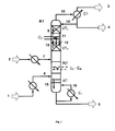
- the inventive method is partially with the help of Fig. 1 to 3 exemplified.
- the Fig. 1 to 3 show the inventive method without any subsequent steps such as disproportionation, further transesterification or purification in any other columns.
- An embodiment of the return of the recovered heat of condensation is only in Fig. 2 shown.
- Fig. 1 describes a reactive rectification in the transesterification column with intermediate condenser in general.
- Fig. 2 describes a reactive rectification with external arrangement of the intermediate condenser and combination with the evaporation of the dialkyl carbonate for the return of the resulting heat of condensation.
- Fig. 3 describes a reactive rectification with external arrangement of the intermediate capacitor and external arrangement of the upper reinforcing member in a separate column.
- Fig. 1 shows a transesterification column K1, in which the two reactant streams, ie containing the aromatic hydroxy compound stream 2 and the dialkyl carbonate containing stream 1 in the region of a reaction zone RZ in the sense of a Jacobstromumesttechnik against each other and reacted to alkylaryl and small amounts of diaryl carbonates.
- the dialkyl carbonate-containing stream 1 can - in particular in continuous process - in addition to the dialkyl also parts of the aromatic hydroxy compound, obtained in the reaction aliphatic hydroxy compound R 1 -OH and / or R 2 -OH (reaction alcohol), very small amounts of at the transesterification incurred Alkylarylcarbonats and / or diaryl carbonate and in the reaction resulting undesirable minor components.
- the stream 1 containing the dialkyl carbonate can be, for example, 0 to 5% by weight, preferably 0.05 to 3% by weight and more preferably 0.05 to 2% by weight of the reaction alcohol, 0 to 40% by weight, preferably 0 to 10% by weight.
- the stream containing the dialkyl carbonate preferably contains from 50 to 100% by weight of dialkyl carbonate, based on the total weight of the dialkyl carbonate-containing stream, with the proportions of the individual abovementioned components adding to 100% by weight.
- the current containing the aromatic hydroxy compound stream 2 can - in particular in continuous process - in addition to the aromatic hydroxy compound and parts of the dialkyl carbonate obtained in the transesterification Alkylarylcarbonat and / or diaryl carbonate, in very small amounts of the reaction alcohol and undesired by-products formed in the reaction.
- the stream 2 containing the aromatic hydroxy compound can be used to feed the catalyst into the transesterification column.
- the content of catalyst preferably 0 to 5 wt .-%, based on the total weight of the aromatic hydroxy compound-containing stream.
- the stream containing the aromatic hydroxy compound preferably contains from 50 to 100% by weight of aromatic hydroxy compound, based on the total weight of the stream containing the aromatic hydroxy compound, the proportions of the individual abovementioned components adding up to 100% by weight.
- the stream 1 containing the dialkyl carbonate is evaporated before introduction into the column K1 and possibly superheated.
- the stream 2 containing the aromatic hydroxy compound is heated before being introduced into the column K1.
- the educt streams 7 and 8, in each case after evaporation and optionally overheating or after heating, are conducted in the reaction zone RZ in countercurrent to each other, ie the containing the aromatic hydroxy compound stream 7 is at the upper end of the reaction zone RZ in heated, liquid form and the Dialkyl carbonate-containing stream 8 is supplied at the lower end of the reaction zone in gaseous or optionally slightly superheated.
- the resulting in the reaction aliphatic hydroxy compound R 1 -OH and / or R 2 -OH is withdrawn in vapor form together with not yet reacted dialkyl carbonate at the top of the column (13) and the less volatile alkylaryl carbonate together with not yet reacted amounts of the aromatic hydroxy compound, diaryl carbonate and optionally further low-volatility compounds taken as a liquid stream at the bottom of the column K1 (5).
- the energy required to set the desired temperature profile can be effected, inter alia, at the bottom of the column by one or more evaporators E 1 .
- the liquid mixture (15) flowing out of the stripping section or, if the stripping section is not present, out of the reaction zone is partially evaporated.
- stream 16 only steam or a vapor-liquid mixture (stream 16) is obtained at the outlet of the evaporator.
- the steam contained in the stream 16 is supplied to the stripping section (AT) from below or, if no stripping section is present, to the reaction zone from below.
- heat can be supplied by additional intermediate evaporators E 2 -E N.
- the alkylaryl carbonate formed and the diaryl carbonate are concentrated, the disproportionation reaction of alkylaryl carbonate and diaryl carbonate being already used to a greater extent in this part of the column K1 as a result of the depletion of dialkyl carbonate.
- the concentration of the aliphatic hydroxy compound formed in the reaction and of the excess dialkyl carbonate takes place.
- a content of aromatic hydroxy compound (s) in the distillate 4 from 0 to 40 wt .-%, preferably 0 to 10 wt .-%, particularly preferably from 0 to 5 wt .-%, based on the total weight of the distillate 4, can be adjusted .
- the reinforcement part is divided into at least two sections, the upper and the lower reinforcing member, with an intermediate capacitor C 2 between the upper reinforcing member VT 2 and the lower reinforcing member VT 1 .
- This intermediate capacitor C 2 condenses a part of the vapors 10 rising from the lower enrichment part VT 1.
- the vaporous mixture 10 entering the intermediate capacitor C 2 preferably contains 10 to 70% by weight of aromatic hydroxy compound.
- the condensation temperature in the intermediate capacitor C 2 is therefore significantly higher due to relatively high amounts of aromatic hydroxy compound compared to the condensation temperature in the top condenser C1.
- the condensation temperature in the intermediate condenser may preferably be in the range from 100 to 300 ° C., more preferably from 120 to 250 ° C., very preferably from 150 to 240 ° C. and preferably in the range from 0 to 250 in the top condenser ° C, more preferably from 40 to 200 ° C.
- the resulting in the intermediate capacitor C 2 condensate 12 and the effluent from the overlying upper reinforcing member VT 2 liquid 11 is passed to the lower reinforcing member VT 1 .
- the vaporous mixture after the intermediate condenser enters the upper reinforcing part VT 2 .
- the steam 13 coming from the upper enrichment part VT 2 is condensed as far as possible in the condenser C1, the condensate being partially returned as reflux to the upper enrichment part VT 2 (14) and partly taken off as distillate flow 4.
- the distillate stream 4 contains essentially the dialkyl carbonate used in excess and the corresponding resulting in the reaction aliphatic hydroxy compound R 1 -OH and / or R 2 -OH and optionally small amounts of the aromatic hydroxy compound.
- the remaining vapor mixture from the condenser C1 is removed as vapor stream 3.
- the heat of condensation liberated in the intermediate capacitor C 2 can be returned directly or indirectly to the process as described above for the process according to the invention (In Fig. 1 Not shown).
- Fig. 2 shows a particularly preferred embodiment of the method according to the invention, in which the intermediate capacitor is carried out separately outside the column and used in the condensation of the stream 10 in the intermediate capacitor C 2 condensation heat for the evaporation of used in symbolsstromumesttechnik in the transesterification column K1, containing dialkyl carbonate stream 1 used becomes.
- the stream 1 containing the dialkyl carbonate is fed to an evaporation unit C 2 , completely or partially evaporated and optionally still superheated.
- the vaporous mixture 10 of the lower amplifying part VT 1 is passed to the intermediate capacitor C 2 , where it partially condenses.
- Fig. 3 shows a further particularly preferred embodiment of the method according to the invention, in which the intermediate capacitor C 2 and the upper reinforcing member VT 2 are not integrated into the transesterification column K1 but are designed separately outside the column K1.
- the vaporous mixture 10 coming from the lower enrichment part VT 1 is fed to the intermediate condenser C 2 and partially condensed there.
- the remaining steam is supplied to the upper enrichment part VT 2 , which is housed in a separate column K2.
- the liquid 11 coming from the upper reinforcing part VT 2 is supplied to the lower reinforcing part together with the condensate 12 from the intermediate capacitor C 2 (FIG. 12 a).
- the steam 13 coming from the upper enrichment part VT 2 is condensed as far as possible, the condensate being partially returned as reflux to the upper enrichment part VT 2 (14) and partly taken off as distillate stream 4.
- the distillate stream 4 contains essentially the dialkyl carbonate used in excess and the corresponding resulting in the reaction aliphatic hydroxy compound R 1 -OH and / or R 2 -OH and optionally small amounts of the aromatic hydroxy compound.
- the remaining vapor mixture from the condenser C1 is removed as vapor stream 3. Otherwise, this corresponds to Fig. 3 shown method in Fig. 1 shown.
- the preceding explanations for Fig. 1 therefore apply analogously.
- the transesterification column according to the invention preferably has a diameter D RZ of 400 to 20,000 mm in the region of the reaction zone and the reaction zone has a length L RZ of 5,000 to 60,000 mm. Further preferably, the transesterification column according to the invention has a number of theoretical stages n Rz of from 5 to 50 in the reaction zone .
- the reaction zone can also have a number of reheaters n E.
- the ratio of the number of reheater n E in the reaction zone to the number of theoretical stages n RZ is preferably 0 to 2.
- the transesterification column according to the invention in the region of the optional stripping section has a diameter D AT of 100 to 20,000 mm and the stripping section has a length L AT of 100 to 20,000 mm.
- the transesterification column according to the invention preferably has a number of theoretical stages n AT of from 0 to 20 in the stripping section.
- the reinforcing part of the transesterification column according to the invention preferably has a diameter D VT of 200 to 10,000 mm and the entire region of the reinforcing part - including optionally present upper and lower reinforcing part and intermediate condenser - a length L VT of 100 to 30,000 mm, preferably 500 to 30,000 mm. Further preferably, reinforcing member has a total of a number of theoretical stages n VT of 2 to 20.
- the lower reinforcing part of the transesterification column according to the invention has a diameter D VT1 of 200 to 10,000 mm and a length L VT1 of 200 to 10,000 mm
- the upper reinforcing part of the transesterification column according to the invention has a diameter D VT2 of 200 to 10,000 mm and a length L VT2 from 200 to 10,000 mm.
- the ratio of the diameter of the lower reinforcing member to the column diameter in the reaction zone D VT1 : D RZ is preferably 0.3 to 1
- the ratio of the diameter of the upper reinforcing member to column diameter in the reaction zone D VT2 : D RZ is preferably 0.1 to 1 ,
- the intermediate condenser of the transesterification column according to the invention has a length L C2 of 100 to 10,000 mm and the ratio of diameter of the intermediate condenser to column diameter in the reaction zone D C2 : D Rz is preferably from 0.1 to 1.
- Intermediate capacitor has a heat transfer area A C2 of 1 to 5000 m 2 .
- the intermediate condenser can be integrated into the column or designed as a separate intermediate condenser outside the transesterification column. Furthermore, the intermediate condenser and the upper section of the reinforcing part can not be integrated into the transesterification column, but can also be accommodated separately outside the transesterification column.
- the intermediate capacitor various constructions are possible according to the invention, e.g. Plate heat exchanger or tube bundle heat exchanger. Such constructions are known to the person skilled in the art.
- the above-mentioned dimensions and characteristics of the transesterification column according to the invention are preferably for a product amount of more than 100 kg / h, wherein the product amount is to be understood as meaning the sum of the alkylaryl carbonate and / or diaryl carbonate contained in the bottom product.
- a conversion of the given dimensions to smaller amounts of product is familiar to the expert. Also from such conversions resulting transesterification columns are the subject of the present invention.
- Exemplary and also particularly preferred embodiments of the column according to the invention are the Fig. 1 to 3 refer to.
- the transesterification column is operated at a top pressure (above VT 2 ) of 3.6 bar and a reflux ratio of 1.15.
- a temperature of 230 ° C and in the reaction zone, a mean reaction temperature of 215 ° C is set in the bottom of the column.
- a sump evaporator E 1 and intermediate evaporator E 2 -E 4 in the reaction zone are operated with heating steam at a vapor pressure of 35 bar, wherein a natural circulation evaporator is used as bottom evaporator E 1 and used as an intermediate evaporator on the reaction trays integrated heating coil.
- the inlet temperature into the intermediate condenser is 205 ° C, the outlet temperature 193 ° C and the cooling capacity 57 kW.
- the heat of condensation produced during the intermediate condensation can be used to generate heating steam with a heating steam pressure of 8 bar (taut temperature: 170.4 ° C.).
- the required heating power for the evaporation of the dimethyl carbonate-containing stream is 52 kW.
- the evaporation and overheating of the dimethyl carbonate is carried out at a temperature of 135 to 152 ° C, to which the steam used in the intermediate condenser can be used easily.
- the transesterification column is operated at a top pressure (above VT 2 ) of 2 bar and a reflux ratio of 1.15.
- the phenol content in the distillate was 2% by weight.
- a temperature of 227 ° C and in the reaction zone, a mean reaction temperature of 200 ° C is set in the bottom of the column.
- a sump evaporator E 1 is operated with heating steam at a vapor pressure of 35 bar, wherein a natural circulation evaporator is used as bottom evaporator.
- the inlet temperature into the intermediate condenser is 190 ° C, the outlet temperature 183 ° C and the cooling capacity 46 kW.
- the heat of condensation produced during the intermediate condensation can be used to generate heating steam with a heating steam pressure of 8 bar (taut temperature: 170.4 ° C.).
- the vaporization and overheating of the dimethyl carbonate is carried out at a temperature of 122 to 153 ° C, to which the steam used in the intermediate condenser can be used easily.
- the required heating power for the evaporation of the dimethyl carbonate-containing stream is 46 kW.
- the transesterification column was operated without intermediate condenser. To achieve a phenol content of 2% by weight in the distillate, the reflux ratio had to be increased to 2.
- the cooling capacity of the top condenser C1 was 190 kW, that of the evaporator 144 kW.
- the condensation in the top condenser C1 was carried out at temperatures between 125 and 97 ° C.
- the material flow in the column energy is removed at a higher temperature level than the top condenser, so that the energy for the evaporation of a column of the supplied stream can be used. This is associated with saving considerable amounts of energy.
Landscapes
- Chemical & Material Sciences (AREA)
- Organic Chemistry (AREA)
- Chemical Kinetics & Catalysis (AREA)
- Organic Low-Molecular-Weight Compounds And Preparation Thereof (AREA)
- Low-Molecular Organic Synthesis Reactions Using Catalysts (AREA)
- Vaporization, Distillation, Condensation, Sublimation, And Cold Traps (AREA)
Applications Claiming Priority (1)
| Application Number | Priority Date | Filing Date | Title |
|---|---|---|---|
| DE102007024574 | 2007-05-25 |
Publications (2)
| Publication Number | Publication Date |
|---|---|
| EP1995233A2 true EP1995233A2 (fr) | 2008-11-26 |
| EP1995233A3 EP1995233A3 (fr) | 2010-06-02 |
Family
ID=39731483
Family Applications (1)
| Application Number | Title | Priority Date | Filing Date |
|---|---|---|---|
| EP08008796A Withdrawn EP1995233A3 (fr) | 2007-05-25 | 2008-05-10 | Procédé de fabrication de carbonates de diaryle ou d'arylalkyle à partir de carbonates de dialkyle |
Country Status (8)
| Country | Link |
|---|---|
| US (2) | US8003817B2 (fr) |
| EP (1) | EP1995233A3 (fr) |
| JP (1) | JP5580970B2 (fr) |
| KR (1) | KR20080103924A (fr) |
| CN (1) | CN101311161A (fr) |
| RU (1) | RU2480448C2 (fr) |
| SG (1) | SG148127A1 (fr) |
| TW (1) | TWI412516B (fr) |
Families Citing this family (4)
| Publication number | Priority date | Publication date | Assignee | Title |
|---|---|---|---|---|
| DE102008029514A1 (de) * | 2008-06-21 | 2009-12-24 | Bayer Materialscience Ag | Verfahren zur Herstellung von Diarylcarbonaten aus Dialkylcarbonaten |
| DE102009053370A1 (de) * | 2009-11-14 | 2011-05-19 | Bayer Materialscience Ag | Verfahren zur Reinigung von Dialkylcarbonaten |
| SG11201402165VA (en) * | 2011-12-07 | 2014-09-26 | Shell Int Research | A process for producing aromatic carbonates |
| EP2711353B1 (fr) | 2012-09-20 | 2018-10-31 | SABIC Global Technologies B.V. | Procédé pour la fabrication en continu de carbonate d'alkyle aryle et de carbonate de diaryle par recompression de vapeur |
Citations (25)
| Publication number | Priority date | Publication date | Assignee | Title |
|---|---|---|---|---|
| US3642858A (en) | 1969-02-12 | 1972-02-15 | Dow Chemical Co | Carbonate synthesis from alkylene carbonates |
| GB1310514A (en) * | 1969-07-02 | 1973-03-21 | Bligh B R | Process of contunuous distillation |
| US3803201A (en) | 1971-02-22 | 1974-04-09 | Dow Chemical Co | Synthesis of dimethyl carbonate |
| EP0001082A1 (fr) | 1977-09-07 | 1979-03-21 | Bayer Ag | Procédé de préparation de dialkylcarbonates |
| JPS5463023A (en) | 1977-10-26 | 1979-05-21 | Mitsubishi Chem Ind Ltd | Ester exchange of carbonate |
| JPS54125617A (en) | 1978-03-20 | 1979-09-29 | Mitsubishi Chem Ind Ltd | Ester interchange of carbonate |
| EP0039452A2 (fr) | 1980-05-07 | 1981-11-11 | Bayer Ag | Procédé de préparation de polycarbonates aromatiques |
| JPS57176932A (en) | 1981-04-24 | 1982-10-30 | Asahi Chem Ind Co Ltd | Preparation of carbonic acid ester |
| DE3445552A1 (de) | 1983-12-27 | 1985-07-04 | General Electric Co., Schenectady, N.Y. | Verbessertes verfahren zur herstellung von aromatischen carbonaten |
| DE3445555A1 (de) | 1983-12-27 | 1985-07-04 | General Electric Co., Schenectady, N.Y. | Verbessertes verfahren zur herstellung von aromatischen carbonaten |
| JPS61172852A (ja) | 1985-01-29 | 1986-08-04 | Daicel Chem Ind Ltd | 炭酸ジフエニルの製造方法 |
| DD258412A1 (de) | 1987-03-12 | 1988-07-20 | Harzer Gipswerke Rottleberode | Verfluessiger fuer hydrophobe gipsmischungen |
| JPS645588A (en) | 1987-06-26 | 1989-01-10 | Juki Kk | Up-and-down feed quantity control apparatus of sewing machine |
| JPH0193560A (ja) | 1987-10-05 | 1989-04-12 | Asahi Chem Ind Co Ltd | ジアリールカーボネートの製造法 |
| JPH0193580A (ja) | 1987-10-02 | 1989-04-12 | Sagami Chem Res Center | 14−フルオロアントラサイクリン誘導体 |
| DE3809417A1 (de) | 1988-03-21 | 1989-10-12 | Henkel Kgaa | Verfahren zur kontinuierlichen veresterung von fettsaeuren |
| EP0338760A2 (fr) | 1988-04-16 | 1989-10-25 | Mitsui Petrochemical Industries, Ltd. | Procédé de préparation de carbonates aromatiques |
| DE4006520A1 (de) | 1990-03-02 | 1991-09-05 | Bayer Ag | Verfahren zur herstellung von mindestens eine aromatische estergruppe enthaltenden kohlensaeurediestern |
| EP0461274A1 (fr) | 1989-12-28 | 1991-12-18 | Asahi Kasei Kogyo Kabushiki Kaisha | Procede de production en continu de carbonate aromatique |
| DE4036594A1 (de) | 1990-11-16 | 1992-05-21 | Bayer Ag | Verfahren zur herstellung von aromatischen kohlensaeurediestern |
| EP0582931A2 (fr) * | 1992-08-13 | 1994-02-16 | Bayer Ag | Procédé pour la préparation en continue de diarylcarbonates à partir de dialkylcarbonates |
| DE4226756A1 (de) | 1992-08-13 | 1994-02-17 | Bayer Ag | Verfahren zur Herstellung von Dicarbonaten |
| EP0781760A1 (fr) | 1995-12-27 | 1997-07-02 | General Electric Company | Méthode de fabrication continue de carbonates aromatiques |
| WO2004016577A1 (fr) | 2002-08-12 | 2004-02-26 | Mitsubishi Chemical Corporation | Procédé de production de carbonate aromatique |
| WO2006001256A1 (fr) | 2004-06-25 | 2006-01-05 | Asahi Kasei Chemicals Corporation | Procédé servant à produire un carbonate aromatique à l'échelle industrielle |
Family Cites Families (19)
| Publication number | Priority date | Publication date | Assignee | Title |
|---|---|---|---|---|
| DE258412C (fr) | 1911-11-14 | |||
| DE2736062A1 (de) | 1977-08-10 | 1979-02-22 | Bayer Ag | Verfahren zur herstellung aromatischer kohlensaeureester |
| DE2736063A1 (de) | 1977-08-10 | 1979-02-22 | Bayer Ag | Verfahren zur herstellung aromatischer kohlensaeureester |
| DE4006420C5 (de) | 1990-03-01 | 2004-02-05 | Robert Bosch Gmbh | Vorrichtung zum optischen Erfassen von Fremdkörpern oder eines Belags auf der Oberfläche einer optisch transparenten Scheibe |
| JPH07304713A (ja) * | 1994-05-10 | 1995-11-21 | Nippon Shokubai Co Ltd | 芳香族炭酸エステルの製造方法 |
| JP3571761B2 (ja) * | 1994-06-09 | 2004-09-29 | 出光石油化学株式会社 | ジフェニルカーボネートの製造方法 |
| US5731453A (en) * | 1996-03-12 | 1998-03-24 | Ube Industries, Ltd. | Process for producing a diaryl carbonate |
| CN2314840Y (zh) * | 1997-07-15 | 1999-04-21 | 清华大学 | 一种新型的催化精馏塔 |
| US6093842A (en) * | 1998-09-25 | 2000-07-25 | General Electric Company | Process for continuous production of carbonate esters |
| JP2001093560A (ja) | 1999-09-27 | 2001-04-06 | Kashimakita Kyodo Hatsuden Kk | レドックスフロー電池 |
| US6294684B1 (en) * | 1999-12-08 | 2001-09-25 | General Electric Company | Method and apparatus for the continuous production of diaryl carbonates |
| US6515187B1 (en) * | 2001-10-03 | 2003-02-04 | Atofina Chemicals, Inc. | Process for recovering acrolein or propionaldehyde from dilute aqueous streams |
| AU2003206228A1 (en) * | 2002-02-05 | 2003-09-02 | Lg Chem, Ltd. | Continuous method for preparing aromatic carbonate using a heterogeneous catalyst and a reaction apparatus for the same |
| JP2004063023A (ja) | 2002-07-30 | 2004-02-26 | Renesas Technology Corp | 半導体記憶装置 |
| CN1247289C (zh) * | 2002-08-27 | 2006-03-29 | 中国石油化工股份有限公司 | 催化精馏中间采出新工艺 |
| RU2329250C2 (ru) * | 2003-06-27 | 2008-07-20 | Асахи Касеи Кемикалз Корпорейшн | Способ получения ароматического карбоната |
| CN1247520C (zh) * | 2004-03-25 | 2006-03-29 | 华中科技大学 | 催化精馏合成二芳基碳酸酯的工艺和装置 |
| BRPI0514936A (pt) | 2004-09-27 | 2008-07-01 | Asahi Kasei Chemicals Corp | aperfeiçoamento em um processo industrial para a produção de um carbonato aromático |
| US7288668B2 (en) * | 2005-11-17 | 2007-10-30 | Catalytic Distillation Technologies | Process for making diaryl carbonate |
-
2008
- 2008-05-10 EP EP08008796A patent/EP1995233A3/fr not_active Withdrawn
- 2008-05-16 US US12/121,873 patent/US8003817B2/en not_active Expired - Fee Related
- 2008-05-22 SG SG200803860-6A patent/SG148127A1/en unknown
- 2008-05-22 CN CNA2008100985756A patent/CN101311161A/zh active Pending
- 2008-05-23 RU RU2008120393/04A patent/RU2480448C2/ru not_active IP Right Cessation
- 2008-05-23 JP JP2008135361A patent/JP5580970B2/ja not_active Expired - Fee Related
- 2008-05-23 KR KR1020080048073A patent/KR20080103924A/ko not_active Ceased
- 2008-05-23 TW TW097118986A patent/TWI412516B/zh not_active IP Right Cessation
-
2011
- 2011-05-06 US US13/102,255 patent/US20110206568A1/en not_active Abandoned
Patent Citations (26)
| Publication number | Priority date | Publication date | Assignee | Title |
|---|---|---|---|---|
| US3642858A (en) | 1969-02-12 | 1972-02-15 | Dow Chemical Co | Carbonate synthesis from alkylene carbonates |
| GB1310514A (en) * | 1969-07-02 | 1973-03-21 | Bligh B R | Process of contunuous distillation |
| US3803201A (en) | 1971-02-22 | 1974-04-09 | Dow Chemical Co | Synthesis of dimethyl carbonate |
| EP0001082A1 (fr) | 1977-09-07 | 1979-03-21 | Bayer Ag | Procédé de préparation de dialkylcarbonates |
| JPS5463023A (en) | 1977-10-26 | 1979-05-21 | Mitsubishi Chem Ind Ltd | Ester exchange of carbonate |
| JPS54125617A (en) | 1978-03-20 | 1979-09-29 | Mitsubishi Chem Ind Ltd | Ester interchange of carbonate |
| EP0039452A2 (fr) | 1980-05-07 | 1981-11-11 | Bayer Ag | Procédé de préparation de polycarbonates aromatiques |
| JPS57176932A (en) | 1981-04-24 | 1982-10-30 | Asahi Chem Ind Co Ltd | Preparation of carbonic acid ester |
| DE3445552A1 (de) | 1983-12-27 | 1985-07-04 | General Electric Co., Schenectady, N.Y. | Verbessertes verfahren zur herstellung von aromatischen carbonaten |
| DE3445555A1 (de) | 1983-12-27 | 1985-07-04 | General Electric Co., Schenectady, N.Y. | Verbessertes verfahren zur herstellung von aromatischen carbonaten |
| JPS61172852A (ja) | 1985-01-29 | 1986-08-04 | Daicel Chem Ind Ltd | 炭酸ジフエニルの製造方法 |
| DD258412A1 (de) | 1987-03-12 | 1988-07-20 | Harzer Gipswerke Rottleberode | Verfluessiger fuer hydrophobe gipsmischungen |
| JPS645588A (en) | 1987-06-26 | 1989-01-10 | Juki Kk | Up-and-down feed quantity control apparatus of sewing machine |
| JPH0193580A (ja) | 1987-10-02 | 1989-04-12 | Sagami Chem Res Center | 14−フルオロアントラサイクリン誘導体 |
| JPH0193560A (ja) | 1987-10-05 | 1989-04-12 | Asahi Chem Ind Co Ltd | ジアリールカーボネートの製造法 |
| DE3809417A1 (de) | 1988-03-21 | 1989-10-12 | Henkel Kgaa | Verfahren zur kontinuierlichen veresterung von fettsaeuren |
| EP0338760A2 (fr) | 1988-04-16 | 1989-10-25 | Mitsui Petrochemical Industries, Ltd. | Procédé de préparation de carbonates aromatiques |
| EP0461274A1 (fr) | 1989-12-28 | 1991-12-18 | Asahi Kasei Kogyo Kabushiki Kaisha | Procede de production en continu de carbonate aromatique |
| DE4006520A1 (de) | 1990-03-02 | 1991-09-05 | Bayer Ag | Verfahren zur herstellung von mindestens eine aromatische estergruppe enthaltenden kohlensaeurediestern |
| DE4036594A1 (de) | 1990-11-16 | 1992-05-21 | Bayer Ag | Verfahren zur herstellung von aromatischen kohlensaeurediestern |
| EP0582931A2 (fr) * | 1992-08-13 | 1994-02-16 | Bayer Ag | Procédé pour la préparation en continue de diarylcarbonates à partir de dialkylcarbonates |
| DE4226755A1 (de) | 1992-08-13 | 1994-02-17 | Bayer Ag | Verfahren zur kontinuierlichen Herstellung von Diarylcarbonaten aus Dialkylcarbonaten |
| DE4226756A1 (de) | 1992-08-13 | 1994-02-17 | Bayer Ag | Verfahren zur Herstellung von Dicarbonaten |
| EP0781760A1 (fr) | 1995-12-27 | 1997-07-02 | General Electric Company | Méthode de fabrication continue de carbonates aromatiques |
| WO2004016577A1 (fr) | 2002-08-12 | 2004-02-26 | Mitsubishi Chemical Corporation | Procédé de production de carbonate aromatique |
| WO2006001256A1 (fr) | 2004-06-25 | 2006-01-05 | Asahi Kasei Chemicals Corporation | Procédé servant à produire un carbonate aromatique à l'échelle industrielle |
Non-Patent Citations (6)
| Title |
|---|
| "Ullmann's Encyclopädie der Technischen Chemie", vol. 2, pages: 528 |
| "Ullmans Encyclopädie der techn. Chemie", vol. 3, 1973, pages: 375 |
| ALAN ROSSITER: "Energy Management", KIRK-OTHMER ENCYCLOPEDIA OF CHEMICAL TECHNOLOGY, VOL. 10, 15 October 2004 (2004-10-15), pages 133 - 168, XP055071650, Retrieved from the Internet <URL:http://onlinelibrary.wiley.com/store/10.1002/0471238961.0514051819200509.a01.pub2/asset/enerstei.a01.pdf?v=1&t=hj8747wq&s=540024cc7811c119baa6374a036dbf4f7c345ee7> [retrieved on 20130717] * |
| B. SCHLEPER ET AL., CHEM.-ING.-TECHN., vol. 62, 1990, pages 226 |
| DAN STEINMEYER: "Process Energy Conservation", KIRK-OTHMER ENCYCLOPEDIA OF CHEMICAL TECHNOLOGY, 4 December 2000 (2000-12-04), pages 1 - 27, XP055039951, Retrieved from the Internet <URL:http://onlinelibrary.wiley.com/store/10.1002/0471238961.1618150319200509.a01/asset/procstei.a01.pdf?v=1&t=h7uicrsj&s=228ec4f849b1daa8f83d5cc75953fa5cb52f6061> [retrieved on 20121003] * |
| U. BLOCK, CHEM.-ING. TECHN., vol. 49, 1977, pages 151 |
Also Published As
| Publication number | Publication date |
|---|---|
| US20110206568A1 (en) | 2011-08-25 |
| RU2008120393A (ru) | 2009-11-27 |
| CN101311161A (zh) | 2008-11-26 |
| JP2009051814A (ja) | 2009-03-12 |
| EP1995233A3 (fr) | 2010-06-02 |
| US20080293960A1 (en) | 2008-11-27 |
| TWI412516B (zh) | 2013-10-21 |
| KR20080103924A (ko) | 2008-11-28 |
| RU2480448C2 (ru) | 2013-04-27 |
| TW200911750A (en) | 2009-03-16 |
| US8003817B2 (en) | 2011-08-23 |
| JP5580970B2 (ja) | 2014-08-27 |
| SG148127A1 (en) | 2008-12-31 |
Similar Documents
| Publication | Publication Date | Title |
|---|---|---|
| EP2036880B1 (fr) | Procédé de fabrication de carbonates de diaryle ou d'alkylaryle à partir de carbonates de dialkyle | |
| EP2135857B1 (fr) | Procédé de fabrication de diarylcarbonates à partir de dialkylcarbonates | |
| EP0582931B1 (fr) | Procédé pour la préparation en continue de diarylcarbonates à partir de dialkylcarbonates | |
| EP2322261B1 (fr) | Procédé destiné au nettoyage de carbonates de dialkyle | |
| EP2239249B1 (fr) | Procédé de fabrication de carbonates de diaryle ou d'alkylaryle à partir de carbonates de dialkyle | |
| EP2062868B1 (fr) | Procédé de purification de carbonates de diaryle | |
| JP4292210B2 (ja) | 高純度ジフェニルカーボネートの工業的製造方法 | |
| EP0572870B1 (fr) | Procédé de fabrication de carbonates organiques avec au moins un groupe ester aromatique | |
| EP2457891B1 (fr) | Procédé de fabrication de diarylcarbonates à partir de dialkylcarbonates | |
| EP2354115B1 (fr) | Procédé destiné à la fabrication de carbonates de dialkyle | |
| DE102009030680A1 (de) | Verfahren zur Herstellung von Dialkylcarbonaten aus Alkylencarbonaten und Alkoholen | |
| EP1995233A2 (fr) | Procédé de fabrication de carbonates de diaryle ou d'arylalkyle à partir de carbonates de dialkyle | |
| EP2922810B1 (fr) | Procédé de préparation de carbonates de dialkyle | |
| EP2447244A1 (fr) | Procédé destiné à la fabrication continue de carbonate de dialkyle | |
| EP2447246B1 (fr) | Procédé destiné à la fabrication continue de carbonate de dialkyle | |
| HK1133867A (en) | Processes for purifying diaryl carbonates |
Legal Events
| Date | Code | Title | Description |
|---|---|---|---|
| PUAI | Public reference made under article 153(3) epc to a published international application that has entered the european phase |
Free format text: ORIGINAL CODE: 0009012 |
|
| AK | Designated contracting states |
Kind code of ref document: A2 Designated state(s): AT BE BG CH CY CZ DE DK EE ES FI FR GB GR HR HU IE IS IT LI LT LU LV MC MT NL NO PL PT RO SE SI SK TR |
|
| AX | Request for extension of the european patent |
Extension state: AL BA MK RS |
|
| PUAL | Search report despatched |
Free format text: ORIGINAL CODE: 0009013 |
|
| AK | Designated contracting states |
Kind code of ref document: A3 Designated state(s): AT BE BG CH CY CZ DE DK EE ES FI FR GB GR HR HU IE IS IT LI LT LU LV MC MT NL NO PL PT RO SE SI SK TR |
|
| AX | Request for extension of the european patent |
Extension state: AL BA MK RS |
|
| 17P | Request for examination filed |
Effective date: 20101202 |
|
| AKX | Designation fees paid |
Designated state(s): AT BE BG CH CY CZ DE DK EE ES FI FR GB GR HR HU IE IS IT LI LT LU LV MC MT NL NO PL PT RO SE SI SK TR |
|
| 17Q | First examination report despatched |
Effective date: 20110817 |
|
| RAP1 | Party data changed (applicant data changed or rights of an application transferred) |
Owner name: BAYER INTELLECTUAL PROPERTY GMBH |
|
| STAA | Information on the status of an ep patent application or granted ep patent |
Free format text: STATUS: THE APPLICATION IS DEEMED TO BE WITHDRAWN |
|
| 18D | Application deemed to be withdrawn |
Effective date: 20140930 |