EP1996469B1 - Dispositif pour transporter des groupes de cigarettes ou d'autres objets - Google Patents
Dispositif pour transporter des groupes de cigarettes ou d'autres objets Download PDFInfo
- Publication number
- EP1996469B1 EP1996469B1 EP07723271A EP07723271A EP1996469B1 EP 1996469 B1 EP1996469 B1 EP 1996469B1 EP 07723271 A EP07723271 A EP 07723271A EP 07723271 A EP07723271 A EP 07723271A EP 1996469 B1 EP1996469 B1 EP 1996469B1
- Authority
- EP
- European Patent Office
- Prior art keywords
- deflecting
- turret
- deflection
- region
- movements
- Prior art date
- Legal status (The legal status is an assumption and is not a legal conclusion. Google has not performed a legal analysis and makes no representation as to the accuracy of the status listed.)
- Ceased
Links
- 235000019504 cigarettes Nutrition 0.000 title claims abstract description 59
- 230000033001 locomotion Effects 0.000 claims abstract description 111
- 238000006073 displacement reaction Methods 0.000 claims abstract description 3
- 230000000694 effects Effects 0.000 claims description 28
- 238000004806 packaging method and process Methods 0.000 claims description 14
- 125000004122 cyclic group Chemical group 0.000 claims description 4
- 238000007599 discharging Methods 0.000 claims 2
- 238000011144 upstream manufacturing Methods 0.000 claims 1
- 238000000034 method Methods 0.000 abstract description 6
- 230000001360 synchronised effect Effects 0.000 abstract 1
- 238000012546 transfer Methods 0.000 description 46
- 230000005540 biological transmission Effects 0.000 description 13
- 238000003780 insertion Methods 0.000 description 7
- 230000037431 insertion Effects 0.000 description 7
- 238000010586 diagram Methods 0.000 description 6
- 238000013461 design Methods 0.000 description 4
- 238000004519 manufacturing process Methods 0.000 description 3
- 230000001133 acceleration Effects 0.000 description 2
- 238000001035 drying Methods 0.000 description 2
- 238000012856 packing Methods 0.000 description 2
- 241000208125 Nicotiana Species 0.000 description 1
- 235000002637 Nicotiana tabacum Nutrition 0.000 description 1
- 230000003750 conditioning effect Effects 0.000 description 1
- 230000006735 deficit Effects 0.000 description 1
- 239000003292 glue Substances 0.000 description 1
- 230000005484 gravity Effects 0.000 description 1
- 238000009434 installation Methods 0.000 description 1
- 238000012423 maintenance Methods 0.000 description 1
- 210000000056 organ Anatomy 0.000 description 1
- 230000000737 periodic effect Effects 0.000 description 1
- 238000005096 rolling process Methods 0.000 description 1
- 230000000087 stabilizing effect Effects 0.000 description 1
- 230000032258 transport Effects 0.000 description 1
Images




Classifications
-
- B—PERFORMING OPERATIONS; TRANSPORTING
- B65—CONVEYING; PACKING; STORING; HANDLING THIN OR FILAMENTARY MATERIAL
- B65B—MACHINES, APPARATUS OR DEVICES FOR, OR METHODS OF, PACKAGING ARTICLES OR MATERIALS; UNPACKING
- B65B19/00—Packaging rod-shaped or tubular articles susceptible to damage by abrasion or pressure, e.g. cigarettes, cigars, macaroni, spaghetti, drinking straws or welding electrodes
- B65B19/02—Packaging cigarettes
- B65B19/22—Wrapping the cigarettes; Packaging the cigarettes in containers formed by folding wrapping material around formers
- B65B19/223—Wrapping the cigarettes; Packaging the cigarettes in containers formed by folding wrapping material around formers in a curved path; in a combination of straight and curved paths, e.g. on rotary tables or other endless conveyors
- B65B19/225—Wrapping the cigarettes; Packaging the cigarettes in containers formed by folding wrapping material around formers in a curved path; in a combination of straight and curved paths, e.g. on rotary tables or other endless conveyors the conveyors having continuous movement
-
- B—PERFORMING OPERATIONS; TRANSPORTING
- B65—CONVEYING; PACKING; STORING; HANDLING THIN OR FILAMENTARY MATERIAL
- B65B—MACHINES, APPARATUS OR DEVICES FOR, OR METHODS OF, PACKAGING ARTICLES OR MATERIALS; UNPACKING
- B65B19/00—Packaging rod-shaped or tubular articles susceptible to damage by abrasion or pressure, e.g. cigarettes, cigars, macaroni, spaghetti, drinking straws or welding electrodes
- B65B19/02—Packaging cigarettes
- B65B19/04—Arranging, feeding, or orientating the cigarettes
-
- B—PERFORMING OPERATIONS; TRANSPORTING
- B65—CONVEYING; PACKING; STORING; HANDLING THIN OR FILAMENTARY MATERIAL
- B65B—MACHINES, APPARATUS OR DEVICES FOR, OR METHODS OF, PACKAGING ARTICLES OR MATERIALS; UNPACKING
- B65B19/00—Packaging rod-shaped or tubular articles susceptible to damage by abrasion or pressure, e.g. cigarettes, cigars, macaroni, spaghetti, drinking straws or welding electrodes
- B65B19/02—Packaging cigarettes
- B65B19/04—Arranging, feeding, or orientating the cigarettes
- B65B19/10—Arranging cigarettes in layers each comprising a predetermined number
-
- B—PERFORMING OPERATIONS; TRANSPORTING
- B65—CONVEYING; PACKING; STORING; HANDLING THIN OR FILAMENTARY MATERIAL
- B65B—MACHINES, APPARATUS OR DEVICES FOR, OR METHODS OF, PACKAGING ARTICLES OR MATERIALS; UNPACKING
- B65B19/00—Packaging rod-shaped or tubular articles susceptible to damage by abrasion or pressure, e.g. cigarettes, cigars, macaroni, spaghetti, drinking straws or welding electrodes
- B65B19/02—Packaging cigarettes
- B65B19/04—Arranging, feeding, or orientating the cigarettes
- B65B19/10—Arranging cigarettes in layers each comprising a predetermined number
- B65B19/105—Arranging cigarettes in layers each comprising a predetermined number using rotary drums for withdrawal of successive layers from a hopper
-
- B—PERFORMING OPERATIONS; TRANSPORTING
- B65—CONVEYING; PACKING; STORING; HANDLING THIN OR FILAMENTARY MATERIAL
- B65B—MACHINES, APPARATUS OR DEVICES FOR, OR METHODS OF, PACKAGING ARTICLES OR MATERIALS; UNPACKING
- B65B35/00—Supplying, feeding, arranging or orientating articles to be packaged
- B65B35/30—Arranging and feeding articles in groups
- B65B35/44—Arranging and feeding articles in groups by endless belts or chains
-
- B—PERFORMING OPERATIONS; TRANSPORTING
- B65—CONVEYING; PACKING; STORING; HANDLING THIN OR FILAMENTARY MATERIAL
- B65B—MACHINES, APPARATUS OR DEVICES FOR, OR METHODS OF, PACKAGING ARTICLES OR MATERIALS; UNPACKING
- B65B35/00—Supplying, feeding, arranging or orientating articles to be packaged
- B65B35/30—Arranging and feeding articles in groups
- B65B35/46—Arranging and feeding articles in groups by rotary conveyors
-
- B—PERFORMING OPERATIONS; TRANSPORTING
- B65—CONVEYING; PACKING; STORING; HANDLING THIN OR FILAMENTARY MATERIAL
- B65G—TRANSPORT OR STORAGE DEVICES, e.g. CONVEYORS FOR LOADING OR TIPPING, SHOP CONVEYOR SYSTEMS OR PNEUMATIC TUBE CONVEYORS
- B65G47/00—Article or material-handling devices associated with conveyors; Methods employing such devices
- B65G47/02—Devices for feeding articles or materials to conveyors
- B65G47/04—Devices for feeding articles or materials to conveyors for feeding articles
- B65G47/06—Devices for feeding articles or materials to conveyors for feeding articles from a single group of articles arranged in orderly pattern, e.g. workpieces in magazines
- B65G47/08—Devices for feeding articles or materials to conveyors for feeding articles from a single group of articles arranged in orderly pattern, e.g. workpieces in magazines spacing or grouping the articles during feeding
- B65G47/082—Devices for feeding articles or materials to conveyors for feeding articles from a single group of articles arranged in orderly pattern, e.g. workpieces in magazines spacing or grouping the articles during feeding grouping articles in rows
-
- B—PERFORMING OPERATIONS; TRANSPORTING
- B65—CONVEYING; PACKING; STORING; HANDLING THIN OR FILAMENTARY MATERIAL
- B65G—TRANSPORT OR STORAGE DEVICES, e.g. CONVEYORS FOR LOADING OR TIPPING, SHOP CONVEYOR SYSTEMS OR PNEUMATIC TUBE CONVEYORS
- B65G47/00—Article or material-handling devices associated with conveyors; Methods employing such devices
- B65G47/34—Devices for discharging articles or materials from conveyor
- B65G47/46—Devices for discharging articles or materials from conveyor and distributing, e.g. automatically, to desired points
- B65G47/51—Devices for discharging articles or materials from conveyor and distributing, e.g. automatically, to desired points according to unprogrammed signals, e.g. influenced by supply situation at destination
- B65G47/5104—Devices for discharging articles or materials from conveyor and distributing, e.g. automatically, to desired points according to unprogrammed signals, e.g. influenced by supply situation at destination for articles
- B65G47/5109—Devices for discharging articles or materials from conveyor and distributing, e.g. automatically, to desired points according to unprogrammed signals, e.g. influenced by supply situation at destination for articles first In - First Out systems: FIFO
- B65G47/5113—Devices for discharging articles or materials from conveyor and distributing, e.g. automatically, to desired points according to unprogrammed signals, e.g. influenced by supply situation at destination for articles first In - First Out systems: FIFO using endless conveyors
Definitions
- the present invention relates to a device for conveying cigarette groups or other objects in or in connection with a packaging machine from a receiving station to a dispensing station, with a pocket conveyor - pocket chain - for receiving a respective cigarette group in a region of a conveyor line cyclically, in particular in the area of the receiving station, and driven in the range of another sub-conveying section by a continuously rotating turret, wherein the pocket conveyor rests in the region of the dispensing station on the circumference of the revolver with revolver pockets arranged along the circumference for receiving the cigarette groups by axially parallel displacement during the synchronization of revolver and pocket conveyor, and wherein on the pocket conveyor, a compensating the movement differences between continuous and clockwise drive, superimposed compensation drive is transferable.
- the invention further relates to a device and a method for conveying cigarette groups or other objects in or in connection with a packaging machine with a transfer device for the translational transfer of the articles from an initial position to an end position.
- the object of the present invention is to improve the devices mentioned as part of a packaging machine or the method mentioned.
- the aforementioned device for conveying cigarette groups or other objects from a receiving station to a delivery station is characterized in that the compensation drive a cyclically at least approximately in the circumferential direction of the revolver and / or Herzien exporting, leading the pocket conveyor along a curved deflection path Deflection means of a deflection device, wherein the pocket conveyor rests in the region in which it bears against the circumference of the revolver, with the side facing away from the revolver side on the reciprocating and exporting deflecting means.
- the pocket conveyor in the region in which it abuts against the circumference of the revolver the pocket conveyor is thus moved radially through the compensation drive, i. the deflection, supported or held. There is therefore no risk that the radial positions of the pockets of the pocket conveyor relative to the revolver during the synchronization of turret and pocket conveyor change.
- the inventive positioning and design of the deflection allows a particularly space-saving arrangement of turret, pocket conveyor and deflection or compensating drive.
- the pocket conveyor can easily rest on the turret circumference in a vertical, lateral area, without the fear of the pocket conveyor slipping radially out of the optimum position of installation due to gravity.
- the pocket conveyor is at the EP 0 210 544 at the bottom of the turret, with separate pressure rollers must be provided which tension the pocket conveyor and must ensure that the pocket conveyor is held in the investment area despite particular gravitational forces on the turret.
- the deflection means according to the invention simultaneously fulfills the function of the compensation drive and the function of the pressure rollers.
- such a traction means made of chain links or toothed belt teeth in a curved deflection path on a polygonal shape, but not a curved according to the deflection path shape.
- This polygon shape causes the so-called polygon effect.
- the operating speed of a transmission with such a chain is therefore severely limited.
- the polygon effect has a particularly negative effect.
- fluctuations in the overall length of the bag chain cause the respective cigarette groups have a local offset to the pockets immediately before insertion into the pockets of the bag chain. In extreme cases, this offset can prevent the exact insertion of the respective cigarette group into the pocket.
- a device for deflecting in particular as part of a packaging machine, is formed so that the Polygon effect is reduced or even completely eliminated.
- the deflection of the deflection which is designed to reduce the polygon effect such that the curvature of the deflection varies locally.
- Deflection means generally provide deflection paths with a locally constant curvature, so that the deflection path describes parts of a circle.
- This aspect of the invention is based on the finding that a deviation from this pitch circle shape of the known deflection tracks can be utilized to reduce the polygon effect.
- the deflection means is designed such that the deflection path with locally varying curvature is a function of tangentially adjoining radii of curvature, wherein the spatial course of the deflection path is chosen such that a plurality of feed movements of one before the Deflection region arranged sub-element - incoming partial element - around distances of certain lengths, in an associated sub-element after the deflection - expiring partial element - effect feed movements to stretch each identical lengths.
- the spatial course of the deflection path in the aforementioned manner can thus be achieved to significantly reduce the polygon effect or even eliminate.
- the aforementioned condition should be fulfilled for the largest possible number of feed movements, preferably for all feed movements.
- the number of different feed movements of the incoming part element, which lead to feed movements of the outgoing part element, each with identical lengths, should be greater than an assumed, locally constant curvature of the deflection path. This comparison naturally applies on the assumption that the assumed deflecting path with locally constant curvature otherwise has the same connections to the web sections of the remaining traction means guide path arranged outside the deflecting path region, along which the traction means is guided outside the deflection.
- a significant reduction of the polygon effect can also be achieved if, for a plurality of predetermined different feed movements of the incoming partial element in comparison with a locally constant curvature of the deflection path, the respective deviations of the lengths of the movement caused by the movements of the incoming partial element feed movements of the expiring element of the respective predetermined, different lengths of the incoming sub-element are smaller. Accordingly, it is determined for a plurality of advancing movements of the incoming part element, how large the deviation is between the length of the track, around which the incoming part element is moved and the track length to which - due to the advancing movement of the incoming part element - the expiring part element is moved.
- this deviation should be less than the deviation at a locally constant curvature.
- This comparison naturally also applies on the assumption that the assumed deflecting path with locally constant curvature otherwise has the same connections to the web sections of the remaining traction means guide path arranged outside the deflecting path region, along which the traction means is guided outside the deflection.
- the deflecting path region can be fixed, for example, by two fixed points of the traction means guide path, namely in relation to it on the feed direction of the traction means through a fixed point before the beginning of the curved path portion of the deflection and a fixed point after the end of the curved path portion of the deflection.
- the section of the traction means located within this firmly defined deflection track area must then have the same length within this deflection track orbit for different positions of the traction means.
- such a polygon effect reducing or ideally eliminating diverter is part of a device described above for conveying cigarette groups or other objects in or relating to a packaging machine from a receiving station to a dispensing station, in particular with a continuous revolving folding turret, with a pocket conveyor - Teschenkette - for receiving a respective cigarette group which is cyclically driven in one area of a conveyor line intermittently, in particular in the receiving station and in the field of another sub-conveyor line, wherein the pocket conveyor is guided along at least one deflection with trained to reduce the polygon effect deflection of the aforementioned type.
- a method for conveying cigarette groups or other objects in or in connection with a packaging machine, wherein the objects are translationally transferred from an initial position to an end position by means of a transfer device, and wherein the transfer device comprises a transfer part, which the articles from the initial position is pushed or pushed in the end position, is characterized in that the transfer device comprises a rotary servomotor and a transmission which translates movements of the shaft of the servomotor in one direction of rotation in a translational movement of the transfer member in the forward direction and movements of the shaft in the opposite direction of rotation in a translational return movement of the transfer part in the opposite direction, wherein the
- Servomotor is controlled such that the servo motor shaft cyclically rotates in one or in the opposite direction, so that the transfer part cyclically performs corresponding translational forward and / or backward movements.
- a corresponding device for carrying out the method has the aforementioned transfer device for translational transfer of the objects from the initial position to the end position and is characterized by the rotary servomotor and the operatively connected to the shaft of the servomotor gear, with the rotational movement of the servo motor shaft in the translational movement of the objects translating from the initial position into the final position translating, in particular abutting or pushing, transfer part is translatable.
- the transfer device dispenses with the use of elaborate gears which translate the rotational movement of a shaft in one and the same direction into a reciprocating movement of the transfer part.
- the gear used can have a low-maintenance, low-wear and relatively pollution-prone basic structure.
- the drive member of the transmission with the servo motor shaft are operatively connected and rotatable and the output member of the transmission operatively connected to the transfer part and translationally forward and / or gurbewegbar, especially in a horizontal plane.
- the transmission is preferably a four-bar linkage.
- the transfer part preferably has one or more finger-like slides or push-pulls with which the articles can be pushed or pushed from the initial position into the end position.
- Fig. 1 shows the production of cuboidal packs 10, namely cigarette packs of the type soft cups, in a packing machine. These cigarette packs 10 are used to hold cigarette groups 15 of cigarettes 13, which are produced in a production unit, not shown, and are supplied from the production unit to a cigarette magazine 11 of the packing machine.
- the cigarette magazine 11 has six Ausschub Suitee for individual cigarette groups 15. Each Ausschub Society has shaft groups 12, each formed of several merged shafts. In each slot is located in a conventional manner, a series of superimposed cigarettes 13.
- the cigarette groups 15 are transferred by slide 14 a transfer device 70 from an initial position to an end position, namely from each shaft group 12 respectively pushed out and via a horizontally extending guide plate 16 in the region of a receiving station 19 in pockets 17 as a pocket conveyor - pocket chain 18 - formed, rotating endless traction means pushed.
- the cigarette groups 15 as package contents are then transferred by the pocket chain 18 to a folding turret 24.
- the latter manufactures the packs 10 and transfers them to a transfer turret 67, which forwards the packs 10 for stabilizing glue connections to a drying turret 68.
- the finished packages 10 are finally transported away via a discharge conveyor 69.
- the transfer device 70 is formed. With this transfer device 70, the cigarette groups 15 are moved from an initial position in the shaft groups 12 into an end position within the pockets 17 of the bag chain 18.
- the transfer device 70 has a transfer part 71 with six slides 14.
- the transfer part 71 has a horizontally extending, plate-shaped base part 81, which is connected to the above the base part 81, parallel to this slide 14.
- the slides 14 are as finger-like elements formed with a front, in particular vertically extending sliding surface, with which the cigarette groups 15 are acted upon during the sliding process or at the cigarette groups 15 abut it.
- the transfer part 71 and thus the slide 14 of the shaft groups 12 of the magazine 11 perform translational or linear, namely horizontal back and / or forth movements.
- the transmission 20 is operatively connected to the shaft 22 of a rotary servomotor 21.
- the transmission 20 is designed in such a way that the rotational movements of the shaft 22 driven by the servomotor 21 are converted into translatory movements of the transfer part 71.
- the transfer part 71 assumes the function of the output member of the transmission 20th
- Rotational movements of the shaft 22 in a first direction of rotation lead to movement of the transfer part 71 - and thus the slider 14 - toward the cigarette group 15, i.e., the slider 14. in the forward direction.
- a rotational movement of the shaft 22 in the direction opposite to the first direction of rotation leads to a return movement of the transfer part 71 and the slide 14 of the cigarette group 15 away.
- the transmission 20 has three identical, in each case with the shaft 22 rotatably connected connecting parts 72, 73, 74. These connecting parts 72, 73, 74 are arranged one behind the other in the axial direction at a distance from each other.
- the connecting part 72 having the smallest axial distance to the housing 90 of the servo motor 21 is hereinafter referred to as inner connecting part
- the connecting part 74 with the largest axial distance is referred to as outer connecting part
- the connecting part 73 with a medium axial distance is referred to as a middle connecting part.
- the inner and outer connection parts 72, 74 extend in the same radial direction, while the middle connection part 73 extends in the opposite, ie offset by 180 ° radial direction.
- a rear gear lever 83 is connected via a rotary joint 82.
- the opposite, namely upper end of the gear lever 83 is connected via a rotary joint 84 with the underside of the plate-shaped base part 81 of the transfer part 71.
- the upper end of the gear lever 83 is arranged in the rear end region of the base part 81.
- the hinges 75, 76, 82 are arranged at the connecting parts 72, 73, 74 in each case with a radial distance to the shaft 22, in each case with an identical distance.
- the two front gear levers 77, 78 are each connected via approximately at half their length arranged hinges 85, 86 with further Getriebehebein 87, 88, which are rotatably mounted on respective pivot joints on a stationary housing part 89.
- the length ratios and the arrangement of the individual members and hinges of the transmission 20 are all matched to one another such that the rotational movement of the shaft 22 is converted into a translational movement of the transfer part 71.
- the sliding surfaces of the slides 14 of the transfer part 71 strike the cigarette groups 15 and move them towards the end positions in the pockets 17 of the bag chain 18.
- the speed of the shaft 22 of the servomotor 21 is preferably controlled in this way in that the transfer part 71 or the slides 14 first impinge on the cigarette groups 15 at the lowest possible speed. Subsequently, the speed of the shaft 22 is increased to move the cigarette group 15 as quickly as possible in the end position.
- This speed control makes sense, on the one hand, the pulse transfer to the individual cigarettes when hitting the sliding surfaces so small as possible, so that the cigarette tobacco is compressed as little as possible.
- the highest possible cycle speed is achieved by the subsequent acceleration.
- the cigarette groups 15 does not push into the final position, but to push through a correspondingly large momentum transfer there.
- the pocket chain 18 transports the cigarette groups 15 to a rotating revolver, namely a folding turret 24.
- a section of the pocket chain 18 abuts on the folding turret 24.
- a portion of the pocket chain 18 is in positive engagement with portions of the circumference of the turret 24 by the individual pockets 17 interconnecting toothed webs 26 positively enter recesses of the folding turret 24, namely in recesses of the turret plate 27.
- the particular continuous rotational movement of the folding turret 24 is transmitted to the bag chain 18.
- the folding turret 24 thus acts as a drive of the pocket chain 18th
- cigarette groups 15 are ejected by axially parallel shifts from the pockets 17 of the bag chain 18 and ejected and not shown in detail pockets of the folding turret 24 supplied.
- the movement characteristic of the pocket chain 18 is formed.
- the pocket chain 18 is along a closed Switzerlandstofffeld Entrysbahn or pocket chain guide track in a by the arrows in Fig. 1 specified conveying direction out.
- the bag chain 18 is moved intermittently.
- the bag chain 18 is currently still (standstill phase). This allows the insertion of the cigarette groups 15 through the slider 14 in the pockets 17 of the bag chain 18, and that transverse to the conveying direction of the bag chain 18.
- the bag chain 18 is continuously moved by the continuous rotational movement of the turret 27.
- the synchronization between turret plate 27 and pocket chain 18 in the region of the dispensing station 25 allows the cigarette groups 15 from the pockets 17 of the bag chain 18 transversely to the conveying direction into the pockets of the folding turret 24 to transfer.
- This complex movement characteristic is effected by superposing a cyclic compensating movement on the constant or continuous conveyor drive effected by the turret disk 27.
- the cyclic compensation movement generates a first deflection device 29, which has a deflection means 30 for deflecting the pocket chain 18.
- the deflection means 30 performs cyclically back and / or return movements, namely up and / or down movements in the vertical plane.
- the deflection means 30 is connected in a manner not shown with a suitable drive.
- the deflection means 30 has curved, spaced-apart, inner and outer guide surfaces 31 and 32 for guiding and / or conditioning of the pocket chain 18.
- the guide surfaces 31, 32 are approximately parallel to each other and go terminal over in this respectively connecting, also curved upper or
- the bottom chain guide surfaces 33, 34 are guided along the guide surfaces 31 - 34, wherein the upper and lower transverse guide surfaces 33, 34 for the bag chain each form approximately 180 ° deflections.
- the curvatures of the inner and outer guide surfaces 31, 32 correspond to the curvature of the turret disk 27.
- the deflection means 30 is arranged such that the inner and outer guide surfaces 31, 32 extend parallel to the circumference of the turret disk 27.
- the pocket chain 18 is in the area in which it rests against the circumference of the folding turret 24 - discharge station 25 -, with the of the folding turret 24 facing away from the curved inner guide surface 31 of the deflection means 30 at.
- the back and forth movements of the deflection means 30 are in the circumferential direction of the turret 24, in particular the turret plate 27, depending on the instantaneous phase of movement of the deflection means 30 different sections of the turret 24, i. in particular the turret plate 27, in positive engagement with the pocket chain 18th
- the amplitude of the reciprocating movements of the deflection means 30 is adjusted so that a (short) stoppage phase of the pocket chain 18 in the region of the receiving station 19 is given during a cycle of outward and / or downward movement.
- a second deflecting device 35 In the conveying direction downstream of the receiving station 19, a second deflecting device 35 is arranged.
- This second deflection device 35 has a deflecting means 36 with a curved guide surface or guide contour 37 curved in the manner of a semicircle.
- a 180 ° deflection of the pocket chain 18 is effected.
- the upper run 28 of the pocket chain 18 extending horizontally in the region of the receiving station 19 is deflected along the guide surface 37, so that the lower run 38 runs at least in regions in the horizontal direction antiparallel to the upper run 28.
- the guide surface 37 has no locally constant, but a locally varying curvature in order to reduce the so-called polygon effect.
- This polygon effect causes traction means such as the pocket chain 18 with periodic, in particular equidistantly spaced sub-elements - such as the pockets 17 which are equidistant from each other by the tooth webs 26 - speed variations of the individual sub-elements after the deflection.
- This can lead to fluctuations in the overall length of the pocket chain 18.
- these variations in the overall length of the bag chain 18 may cause in extreme cases that the respective cigarette groups 15 have a local offset to the pockets immediately before insertion into the pockets 17 of the bag chain 18. This offset can prevent the exact insertion of the respective cigarette group 15 into the pocket 17.
- Fig. 5 shows a 180 ° deflection of a trained as a flat belt 39 pulling means along a curved deflection path 40, which is part of an excerpts only endlessly shown Buchstoff Unitsbahn 51, along which the flat belt 39 is guided.
- the curved path section between the points A and B is defined as deflection path 40.
- the deflection path 40 is in straight connections of the remaining Buchstoff Unitsbahn 51 over.
- the deflecting path 40 can also be taken differently, for instance by including sections of the straight connections of the traction means guideway 51.
- the deflection path 40 has, as is customary in the prior art, a locally constant curvature, ie, the curvature has a constant value regardless of the location.
- the curvature can therefore be described by a constant radius of curvature R.
- the deflection path is effected or predetermined by a deflection means, not shown, for example, by a stationary Umlenkkontur with curved deflection surfaces along which the flat belt 39 is guided. A polygon effect does not occur.
- Arbitrary feed movements by a distance of the length X arranged in front of the deflection, any point 41 of the flat belt 39 effect each feed movements to stretching identical lengths of an associated point 42 on the flat belt 39 to the deflection.
- Fig. 6 shows a diagram describing this situation.
- the diagram represents a Cartesian coordinate system in which the respective path length of the advancing movement of the point 42 to the deflecting region is plotted as the ordinate, and the path length of the advancing movement of the point 41 in front of the deflecting region is plotted as the abscissa.
- the values entered in the coordinate system describe a straight line 48 with the increase 1, which begins at the origin.
- Each shift of the point 41 by a distance X thus causes a shift of the point 42 by an identical route length Y.
- Fig. 7 shows instead of a flat belt 39, a chain 43 of individual sub-elements, namely chain links 44 which are connected to each other at equidistant spacing by straight intermediate webs 45.
- the chain 43 is along the deflection path 40 of the Fig. 5 guided with the same, locally constant curvature.
- Fig. 6 describes the movement of a flat belt describes Fig. 8 Now, the movement of the chain 43 along the deflection path 40.
- feed movements to different lengths X are the movements caused by these movements feed distances by lengths Y of an expiring chain link 47 after the Deflection, ie after the point B, faced.
- the dashed line 50 in Fig. 8 represents the ideal course of movement, as it is caused by the flat belt 39 when it is guided along the deflection path 40 without polygon effect.
- the solid line 49 shows the movement of the link chain.
- Each movement by a distance of the length X of the incoming chain link 46 causes different, non-identical feed movements by stretching the length Y of the expiring chain link 47.
- the different lengths of line Y are caused by the polygon effect, ie by the deviating from the curvature of the deflection path 40 polygon shape of Chain 43 within the deflection.
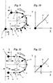
- the chain 43 does not lead along a deflection path 40 with constant curvature, but along a Deflection track 52 with locally variable curvature.
- feed movements about distances of a certain length X of the incoming chain link 46 in comparison to the prior art cause feed movements by lengths Y of the outgoing chain link 47 which are identical to the line lengths X or at least in a very narrow interval by the same value ,
- the curve 49 of the movement sequence of the link chain nestles in this case much better to the ideal course of motion 48, cf. Fig. 10 , as in the deflection with constant radius of curvature according to Fig. 7, Fig. 8 the case is.
- a corresponding, the deflection path 52 causing deflecting device such as the deflection device 35 from Fig. 1 , formed such that the deflection path 52 with locally varying curvature is a function of tangentially adjoining radii of curvature, wherein the spatial course of the deflection path 52 is selected such that at least a plurality of feed movements of the arranged before the deflection, incoming chain link 46 to certain distances Lengths X at the associated expiring chain link 47 after the deflection cause feed movements to distances Y each having identical lengths.
- a particularly good reduction of the polygon effect can be achieved if the condition is met for at least a plurality of predetermined different feed movements of the incoming chain link 46 by track lengths X, that the respective deviations of the lengths Y of the corresponding feed movements of the expiring chain link 47 of the respective predetermined lengths of the track X of the incoming chain link 46 are smaller compared to the use of the deflection path 40 with locally constant curvature. Accordingly, it is determined for a plurality of feed movements of the incoming chain link 46, how large the deviation is between the distance X, by which the incoming chain link 46 is moved and the route length Y to the - due to the advancing movement of the incoming chain link 46 - the expiring Chain link 47 is moved. For a plurality of feed movements of the incoming Chain link 46, this deviation should be less than the deviation in the locally constant curvature of the deflection path 40th
- the aforementioned condition is met by the deflection path 52: the movement curve 49 of the Fig. 10 snuggles much closer to the ideal movement curve 48 as the movement curve 49 of Fig. 8 ,
- the polygon effect can be reduced, the greater the number of advancing movements, in which the condition already mentioned above is met, after which the deflection path 52 with locally varying curvature is a function of tangentially adjoining radii of curvature and the spatial course of the deflection path 52 in such a way it is selected that at least a plurality of feed movements of the incoming chain link 46 cause feed movements for distances Y of respectively identical lengths by distances of certain lengths X at the associated outgoing chain link 47.
- this condition should be met for the largest possible number of feed movements, preferably for all feed movements.
- Fig. 11 and the associated one Fig. 12 is one opposite the Fig. 9 changed position of the chain 43 shown after a feed movement of the incoming chain link 46 by a distance of length a. This feed movement causes a feed movement of the length b of the expiring chain link 47.
- the two lengths a and b are identical, as in the in Fig. 12 can be seen shown curve.
- the curvature of the guide surface 37 of the deflection means 36 of the packaging machine is the Fig. 1 - 4th locally varying formed to reduce the polygon effect of the rotating pocket chain 18.
- the special design of the guide surface 37 already causes a sufficient reduction of the polygon effect in the present case, which, inter alia, leads to the total length of the pocket chain 18 being identical during the entire cycle of the pocket chain 18.
- one or more of the relevant guide surfaces or guide contours 31-34 of the deflection means 30 must have suitable locally varying curvatures.
- the curved guide surfaces of rails 53, 54 of the packaging machine, through which the bag chain 18 is first guided horizontally and then deflected from the horizontal up or down, can be formed in accordance with the invention in order to reduce any polygonal effects.
- the deflection means each have fixed guide surfaces or guide contours with locally varying curvature.
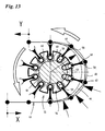
- the deflecting device 55 of Fig. 13 On the other hand, as deflecting means 56, a wheel 57 which is rotatable by means of a drive, not shown, has guide levers 58 which are displaceable in the radial direction and displaceable in radial direction. The guide levers 58 protrude radially beyond the circumference of the wheel 57. Terminally, the guide lever 58 are operatively connected to the wheel 57 side facing cam rollers 60.
- the guide levers 58 On the side facing away from the wheel 57, the guide levers 58 have, in particular, terminal concave receptacles 61 for the - temporary - guidance of, for example, link joints 62 of a chain 63.
- the individual cam rollers 60 roll during the rotation of the wheel 57 on a stationary guide surface, namely a curve contour 64 from.
- the guide lever 58 By rolling the cam rollers 60 on the cam contour 64, the guide lever 58 perform superimposed translational and rotational movements.
- the chain 63 can accordingly by the Deflection device 55 are guided along a deflection path 65, whose curvature varies locally.
- the curvature values of the deflecting path 65 can be predetermined by suitable dimensioning of the individual components of the deflecting device 55.
Landscapes
- Engineering & Computer Science (AREA)
- Mechanical Engineering (AREA)
- Wrapping Of Specific Fragile Articles (AREA)
- Specific Conveyance Elements (AREA)
Abstract
Claims (9)
- Dispositif pour transporter des groupes de cigarettes (15) ou d'autres objets dans ou en relation avec une machine d'emballage depuis un poste de réception (19) jusqu'à un poste de distribution (25), comprenant un transporteur à poches - chaîne à poche (18) - pour recevoir un groupe de cigarettes respectif (15), qui est entraîné dans une région d'une section de transport de manière cadencée, en particulier dans la région du poste de réception (19), et dans la région d'une autre section de transport partielle par une tourelle tournant en continu, le transporteur à poches (18) s'appliquant dans la région du poste de distribution (25) contre la périphérie de la tourelle (24) avec des poches de tourelle disposées le long de la périphérie pour recevoir les groupes de cigarettes (15) par déplacement d'axe parallèle pendant le fonctionnement synchronisé de la tourelle (24) et du transporteur à poches (18), et un entraînement d'équilibrage superposé, équilibrant les différences de mouvement entre l'entraînement continu et l'entraînement cadencé pouvant être transmis au transporteur à poches (18), caractérisé en ce que l'entraînement d'équilibrage est un moyen déflecteur (30) d'un dispositif déflecteur (29), effectuant des mouvements de va-et-vient cadencés au moins approximativement dans la direction périphérique de la tourelle et guidant le transporteur à poches (18) le long d'une trajectoire périphérique courbe, le transporteur à poches (18), dans la région dans laquelle il s'applique contre la périphérie de la tourelle (24), s'appliquant par son côté opposé à la tourelle (24) contre le moyen déflecteur (30) effectuant des mouvements de va-et-vient cadencés.
- Dispositif selon la revendication 1, caractérisé en ce que le transporteur à poches (18) est en prise par engagement par correspondance géométrique avec la périphérie de la tourelle (24), en particulier par le biais de nervures dentées (26) de poches (17) qui entrent par engagement par correspondance géométrique dans des renfoncements de la tourelle (24), notamment du plateau (27) de la tourelle.
- Dispositif selon l'une quelconque ou plusieurs des revendications 1 et 2, caractérisé en ce que le transporteur à poches (18), dans la région dans laquelle il s'applique contre la périphérie de la tourelle (24), notamment dans laquelle il est en engagement par correspondance géométrique avec la tourelle (24), s'applique par son côté opposé à la tourelle (24) contre le moyen déflecteur (30) effectuant des mouvements de va-et-vient, en particulier des mouvements de levage et/ou d'abaissement.
- Dispositif selon l'une quelconque ou plusieurs des revendications précédentes, caractérisé en ce qu'une portion partielle du transporteur à poches (18) associée à la tourelle (24) peut être déplacée avec une vitesse constante et un tronçon supérieur (28) ou un tronçon inférieur (38) associé au poste de réception (19) peut être déplacé de manière cadencée, à savoir avec une phase d'immobilisation.
- Dispositif selon l'une quelconque ou plusieurs des revendications précédentes, caractérisé en ce que le tronçon supérieur (28) ou le tronçon inférieur (38) du transporteur à poches (18) se déplaçant de manière cadencée subit, pendant un mouvement de levage et/ou d'abaissement du moyen déflecteur (30), une phase d'immobilisation.
- Dispositif selon l'une quelconque ou plusieurs des revendications précédentes, caractérisé en ce que le moyen déflecteur du dispositif déflecteur (29, 35) est réalisé pour réduire l'effet de polygonalité de telle sorte que la courbure de la trajectoire périphérique (52, 65) varie localement.
- Dispositif selon l'une quelconque ou plusieurs des revendications précédentes, caractérisé en ce que le moyen déflecteur (30, 36, 56) est réalisé de telle sorte que la trajectoire périphérique (52, 65) de courbure variant localement satisfasse aux conditions marginales suivantes :a) la courbure variant localement de la trajectoire périphérique (52, 65) est une fonction de rayons de courbure se raccordant tangentiellement les uns aux autres,b) l'allure spatiale de la trajectoire périphérique (52, 65) est sélectionnée de telle sorte qu'une pluralité de mouvements d'avance d'un élément partiel disposé avant la région périphérique - élément partiel entrant - effectuent sur des distances de longueurs déterminées, pour un élément partiel associé après la région de déflexion - élément partiel sortant -, des mouvements d'avance sur des distances de longueurs respectivement identiques.
- Dispositif selon l'une quelconque ou plusieurs des revendications précédentes, caractérisé en ce que le nombre de mouvements d'avance différents de l'élément partiel entrant, qui conduisent à des mouvements d'avance de l'élément partiel sortant avec des distances de longueurs identiques, est supérieur au nombre de mouvements dans le cas d'une courbure localement constante de la trajectoire périphérique (52, 65), et/ou en ce que pour une pluralité de mouvements d'avance différents de l'élément partiel entrant, les écarts respectifs des distances en longueur des mouvements d'avance de l'élément sortant provoqués par les mouvements de l'élément partiel entrant par rapport aux distances en longueur différentes respectives de l'élément partiel entrant sont inférieurs aux écarts dans le cas d'une courbure localement constante de la trajectoire périphérique (52, 65).
- Dispositif selon l'une quelconque ou plusieurs des revendications précédentes, caractérisé en ce que parmi les trajectoires périphériques théoriquement possibles pour le moyen de traction (18, 43, 63) pour la déflexion souhaitée, avec une courbure variant localement, dans lesquelles la courbure de chaque trajectoire périphérique est une fonction de rayons de courbure se raccordant tangentiellement les uns aux autres, on choisit celle pour laquelle la longueur de la pièce partielle du moyen de traction se trouvant à chaque fois à l'intérieur de la région de la trajectoire périphérique est identique pour un nombre particulièrement grand de positions différentes du moyen de traction, de préférence pour un nombre maximal de positions.
Priority Applications (1)
| Application Number | Priority Date | Filing Date | Title |
|---|---|---|---|
| EP09010785A EP2123563B1 (fr) | 2006-03-20 | 2007-03-15 | Procédé et dispositif de transport de groupes de cigarettes ou autres objets |
Applications Claiming Priority (2)
| Application Number | Priority Date | Filing Date | Title |
|---|---|---|---|
| DE200610013038 DE102006013038A1 (de) | 2006-03-20 | 2006-03-20 | Vorrichtung zur Umlenkung eines Zugmittels, insbesondere für eine Fertigungs- und/oder Verpackungsmaschine, zur Herstellung und/oder Verpackung von Zigaretten |
| PCT/EP2007/002277 WO2007107284A2 (fr) | 2006-03-20 | 2007-03-15 | Dispositif et procede pour transporter des groupes de cigarettes ou d'autres objets |
Related Child Applications (2)
| Application Number | Title | Priority Date | Filing Date |
|---|---|---|---|
| EP09010785A Division EP2123563B1 (fr) | 2006-03-20 | 2007-03-15 | Procédé et dispositif de transport de groupes de cigarettes ou autres objets |
| EP09010785.5 Division-Into | 2009-08-24 |
Publications (2)
| Publication Number | Publication Date |
|---|---|
| EP1996469A2 EP1996469A2 (fr) | 2008-12-03 |
| EP1996469B1 true EP1996469B1 (fr) | 2012-05-02 |
Family
ID=38121775
Family Applications (2)
| Application Number | Title | Priority Date | Filing Date |
|---|---|---|---|
| EP07723271A Ceased EP1996469B1 (fr) | 2006-03-20 | 2007-03-15 | Dispositif pour transporter des groupes de cigarettes ou d'autres objets |
| EP09010785A Ceased EP2123563B1 (fr) | 2006-03-20 | 2007-03-15 | Procédé et dispositif de transport de groupes de cigarettes ou autres objets |
Family Applications After (1)
| Application Number | Title | Priority Date | Filing Date |
|---|---|---|---|
| EP09010785A Ceased EP2123563B1 (fr) | 2006-03-20 | 2007-03-15 | Procédé et dispositif de transport de groupes de cigarettes ou autres objets |
Country Status (3)
| Country | Link |
|---|---|
| EP (2) | EP1996469B1 (fr) |
| DE (1) | DE102006013038A1 (fr) |
| WO (1) | WO2007107284A2 (fr) |
Families Citing this family (7)
| Publication number | Priority date | Publication date | Assignee | Title |
|---|---|---|---|---|
| EP2586718B1 (fr) * | 2011-10-31 | 2014-05-28 | Tetra Laval Holdings & Finance S.A. | Unité de pliage de production de paquets pliés de produits alimentaires pouvant être versés à partir de paquets scellés relatifs |
| DE102012104213B4 (de) | 2012-05-15 | 2020-01-09 | Taktomat Kurvengesteuerte Antriebssysteme Gmbh | Transportsystem für Behandlungsmaschinen sowie Behandlungsmaschine |
| ITUB20152457A1 (it) * | 2015-07-24 | 2017-01-24 | Elisabetta Tessari | Magazzino accumulatore temporaneo di prodotti allungati, in particolare tubolari |
| CN105857690B (zh) * | 2016-04-29 | 2017-11-17 | 温州中科包装机械有限公司 | 香烟自动装盒机 |
| CN106742276B (zh) * | 2016-12-29 | 2023-11-14 | 协养堂大健康科技(广东)股份有限公司 | 一种袋中袋高速包装方法及其装置 |
| CN106516250B (zh) * | 2016-12-29 | 2019-03-12 | 广东宏川环宇科技有限公司 | 一种袋中袋高速自动包装机 |
| DE102022104323A1 (de) | 2022-02-23 | 2023-08-24 | Multivac Sepp Haggenmüller Se & Co. Kg | Umlenkeinrichtung für Produkte |
Family Cites Families (27)
| Publication number | Priority date | Publication date | Assignee | Title |
|---|---|---|---|---|
| DE166326C (fr) * | ||||
| DE577312C (de) * | 1933-05-29 | Hermann Hellberg | Daumentreibscheibe fuer Bandfoerderer | |
| US1647265A (en) * | 1926-04-07 | 1927-11-01 | American Mach & Foundry | Feeding device for cigarette-packaging machines |
| DE662041C (de) * | 1937-06-02 | 1938-07-04 | Albert Gruenig | Kettengreiferscheibe |
| DE1050259B (de) * | 1956-09-19 | 1959-02-05 | Haum-Werke Korber S. Co K G Hamburg-Bergedorf | Zahl- und Full maschine fur Filterstabe |
| DE1152593B (de) * | 1958-08-19 | 1963-08-08 | Karlsruhe Augsburg Iweka | Mit Tragrollen versehene Blechhaltevorrichtung an Tafelscheren |
| GB926776A (en) * | 1960-01-14 | 1963-05-22 | Amf Sasib S P A | Apparatus for grouping packages delivered from pneumatic conveyors |
| BE662898A (fr) * | 1964-04-22 | |||
| GB1075827A (en) * | 1964-10-23 | 1967-07-12 | Kurt Koerber | Method and apparatus for forming cigarette blocks |
| DE2407580A1 (de) * | 1974-02-16 | 1975-08-21 | Focke Pfuhl Verpack Automat | Anlage zum herstellen und verpacken von zigaretten o.dgl. sowie verfahren zur speicherung derselben |
| DE2515898A1 (de) * | 1975-04-11 | 1976-10-21 | Hauni Werke Koerber & Co Kg | Vorrichtung zum fuellen eines behaelters mit stabfoermigen artikeln der tabakverarbeitenden industrie |
| DE2858074C2 (de) * | 1978-02-15 | 1985-08-01 | Focke & Co, 2810 Verden | Vorrichtung zur Übergabe von eingehüllten Zigarettengruppen an einen umlaufenden Revolver |
| DE2919927C2 (de) * | 1979-05-17 | 1986-01-02 | Focke & Co, 2810 Verden | Vorrichtung zur Bildung und zum anschließenden Verpacken von Gruppen stabförmiger Gegenstände, insbesondere von Zigaretten-Gruppen |
| US4485914A (en) * | 1982-09-30 | 1984-12-04 | Ibm Corporation | Variable drive pin projection mechanism for a belt sprocket drive wheel |
| US4607477A (en) * | 1983-04-15 | 1986-08-26 | Molins Plc | Cigarette packing machines |
| DE3527742C2 (de) * | 1985-08-02 | 1996-06-13 | Focke & Co | Vorrichtung zum Fördern von Zigaretten-Gruppen |
| DD246092A1 (de) * | 1986-02-12 | 1987-05-27 | Univ Dresden Tech | Kettentrieb mit polygonscheibe |
| DE4443590C2 (de) * | 1994-12-07 | 1998-01-22 | Brueckner Trockentechnik Gmbh | Kettenrad für eine Transportkette |
| DE19727699A1 (de) * | 1997-06-23 | 1998-12-24 | Mannesmann Ag | Ketteneinlauf an Raupenketten-Ziehmaschinen |
| DE19825943A1 (de) * | 1998-06-11 | 1999-12-16 | Focke & Co | Verfahren und Vorrichtung zum Reinigen von Verpackungsmaschinen |
| DE19849236C2 (de) * | 1998-08-08 | 2001-06-13 | Kone Corp | Einrichtung zum Führen einer Kette im Bereich von Kettenrädern eines Stetigförderers |
| US6141943A (en) * | 1998-09-21 | 2000-11-07 | F. R. Drake Company | Food article loading head and method |
| DE19902453A1 (de) * | 1999-01-22 | 2000-07-27 | Bosch Gmbh Robert | Vorrichtung zum Einschieben von Gegenständen, insbesondere Blisterstreifen, in Faltschachteln |
| DE19945921A1 (de) * | 1999-09-23 | 2001-06-13 | Burkhard Grobbel | Antriebs-Kettenrad für Gelenkketten, insbesondere Förderketten |
| DE20006285U1 (de) * | 2000-04-05 | 2000-09-28 | Toth-Müller, Stefan Gerson, Dr.-Ing., 63654 Büdingen | Kettenantriebe |
| US6685003B2 (en) * | 2001-12-28 | 2004-02-03 | Otis Elevator Company | Pulse-free escalator |
| DE202005017406U1 (de) * | 2005-11-08 | 2006-03-09 | Toth-Müller, Stefan Gerson, Dr.-Ing. | Kettenzahnrad |
-
2006
- 2006-03-20 DE DE200610013038 patent/DE102006013038A1/de not_active Withdrawn
-
2007
- 2007-03-15 WO PCT/EP2007/002277 patent/WO2007107284A2/fr not_active Ceased
- 2007-03-15 EP EP07723271A patent/EP1996469B1/fr not_active Ceased
- 2007-03-15 EP EP09010785A patent/EP2123563B1/fr not_active Ceased
Also Published As
| Publication number | Publication date |
|---|---|
| EP2123563A1 (fr) | 2009-11-25 |
| DE102006013038A1 (de) | 2007-09-27 |
| WO2007107284A3 (fr) | 2007-12-21 |
| EP2123563B1 (fr) | 2012-05-23 |
| WO2007107284A2 (fr) | 2007-09-27 |
| EP1996469A2 (fr) | 2008-12-03 |
Similar Documents
| Publication | Publication Date | Title |
|---|---|---|
| EP1731450B1 (fr) | Dispositif pour séparer, transporter et grouper des articles | |
| EP3334669B1 (fr) | Dispositif de transport et procédé de transport employant un tel dispositif de transport | |
| EP0210544B1 (fr) | Dispositif pour transporter des groupes de cigarettes | |
| EP1522508B1 (fr) | Dispositif de séparation, de synchronisation et d'accumulation | |
| EP2123563B1 (fr) | Procédé et dispositif de transport de groupes de cigarettes ou autres objets | |
| NZ765827A (en) | Continuous motion packaging machine with carton turning station | |
| DE10312695B4 (de) | Einrichtung und Verfahren zum Fördern und Speichern von Fördergut | |
| DE19940243A1 (de) | Fördervorrichtung für Tragplatten, Thermoformmaschine und Verfahren zum Thermoformen von Gegenständen | |
| EP3013696A1 (fr) | Dispositif de formation d'unités d'emballage | |
| EP2903919A1 (fr) | Dispositif de transport pour marchandises et procédé permettant de faire fonctionner un dispositif de transport | |
| DE102018002280A1 (de) | Endlos umlaufende Behälter-Fördervorrichtung in einer Verpackungsmaschine | |
| DE4439728A1 (de) | Vorrichtung zum Befördern und Gruppieren von Gegenständen | |
| WO2024223784A1 (fr) | Dispositif et procédé de rotation de contenants d'emballage | |
| DE7738506U1 (de) | Transporteinrichtung, insbesondere fuer die schrittweise befoerderung von werkstuecken bei pressen | |
| DE102006045478A1 (de) | Faltschachtelabzug für Verpackungsmaschine | |
| EP1050471A2 (fr) | Transporteur pour boítes pliantes dans une machine d'emballage | |
| DE102007026213A1 (de) | Pufferstation | |
| EP0458733B1 (fr) | Méthode et dispositif pour transporter des produits imprimés | |
| DE102007004324B4 (de) | Transporteinrichtung zum Transport von Gegenständen | |
| DE60309133T2 (de) | Vorrichtung zur anpassung des abstandes zwischen förderfingern an die länge des produktes | |
| DE2916794C2 (fr) | ||
| DE102016121575B4 (de) | Einrichtung und Verfahren zum Aufteilen von hintereinander geförderten Produkten | |
| EP3960663B1 (fr) | Dispositif et procédé de manutention de récipients | |
| DE2601738A1 (de) | Verfahren und vorrichtung zum teilen eines stromes stabfoermiger gegenstaende | |
| DE10137196C1 (de) | Transportbahn für eine Schlauchbeutelverpackungsmaschine |
Legal Events
| Date | Code | Title | Description |
|---|---|---|---|
| PUAI | Public reference made under article 153(3) epc to a published international application that has entered the european phase |
Free format text: ORIGINAL CODE: 0009012 |
|
| 17P | Request for examination filed |
Effective date: 20080813 |
|
| AK | Designated contracting states |
Kind code of ref document: A2 Designated state(s): DE GB IT |
|
| DAX | Request for extension of the european patent (deleted) | ||
| RBV | Designated contracting states (corrected) |
Designated state(s): DE GB IT |
|
| 17Q | First examination report despatched |
Effective date: 20091229 |
|
| REG | Reference to a national code |
Ref country code: DE Ref legal event code: R079 Ref document number: 502007009821 Country of ref document: DE Free format text: PREVIOUS MAIN CLASS: B65B0019220000 Ipc: B65B0019100000 |
|
| GRAP | Despatch of communication of intention to grant a patent |
Free format text: ORIGINAL CODE: EPIDOSNIGR1 |
|
| RIC1 | Information provided on ipc code assigned before grant |
Ipc: B65B 19/10 20060101AFI20111014BHEP |
|
| RTI1 | Title (correction) |
Free format text: APPARATUS FOR CONVEYING CIGARETTE GROUPS OR OTHER OBJECTS |
|
| GRAS | Grant fee paid |
Free format text: ORIGINAL CODE: EPIDOSNIGR3 |
|
| GRAA | (expected) grant |
Free format text: ORIGINAL CODE: 0009210 |
|
| AK | Designated contracting states |
Kind code of ref document: B1 Designated state(s): DE GB IT |
|
| REG | Reference to a national code |
Ref country code: GB Ref legal event code: FG4D Free format text: NOT ENGLISH |
|
| REG | Reference to a national code |
Ref country code: DE Ref legal event code: R096 Ref document number: 502007009821 Country of ref document: DE Effective date: 20120628 |
|
| PLBE | No opposition filed within time limit |
Free format text: ORIGINAL CODE: 0009261 |
|
| STAA | Information on the status of an ep patent application or granted ep patent |
Free format text: STATUS: NO OPPOSITION FILED WITHIN TIME LIMIT |
|
| 26N | No opposition filed |
Effective date: 20130205 |
|
| REG | Reference to a national code |
Ref country code: DE Ref legal event code: R097 Ref document number: 502007009821 Country of ref document: DE Effective date: 20130205 |
|
| PGFP | Annual fee paid to national office [announced via postgrant information from national office to epo] |
Ref country code: GB Payment date: 20160309 Year of fee payment: 10 |
|
| PGFP | Annual fee paid to national office [announced via postgrant information from national office to epo] |
Ref country code: DE Payment date: 20160323 Year of fee payment: 10 |
|
| PGFP | Annual fee paid to national office [announced via postgrant information from national office to epo] |
Ref country code: IT Payment date: 20160324 Year of fee payment: 10 |
|
| REG | Reference to a national code |
Ref country code: DE Ref legal event code: R119 Ref document number: 502007009821 Country of ref document: DE |
|
| GBPC | Gb: european patent ceased through non-payment of renewal fee |
Effective date: 20170315 |
|
| PG25 | Lapsed in a contracting state [announced via postgrant information from national office to epo] |
Ref country code: DE Free format text: LAPSE BECAUSE OF NON-PAYMENT OF DUE FEES Effective date: 20171003 |
|
| PG25 | Lapsed in a contracting state [announced via postgrant information from national office to epo] |
Ref country code: IT Free format text: LAPSE BECAUSE OF NON-PAYMENT OF DUE FEES Effective date: 20170315 Ref country code: GB Free format text: LAPSE BECAUSE OF NON-PAYMENT OF DUE FEES Effective date: 20170315 |