EP1997412B1 - Procédé de fonctionnement d'un aspirateur - Google Patents
Procédé de fonctionnement d'un aspirateur Download PDFInfo
- Publication number
- EP1997412B1 EP1997412B1 EP08008709A EP08008709A EP1997412B1 EP 1997412 B1 EP1997412 B1 EP 1997412B1 EP 08008709 A EP08008709 A EP 08008709A EP 08008709 A EP08008709 A EP 08008709A EP 1997412 B1 EP1997412 B1 EP 1997412B1
- Authority
- EP
- European Patent Office
- Prior art keywords
- vacuum cleaner
- operating
- floor covering
- motor
- category
- Prior art date
- Legal status (The legal status is an assumption and is not a legal conclusion. Google has not performed a legal analysis and makes no representation as to the accuracy of the status listed.)
- Active
Links
Images


Classifications
-
- A—HUMAN NECESSITIES
- A47—FURNITURE; DOMESTIC ARTICLES OR APPLIANCES; COFFEE MILLS; SPICE MILLS; SUCTION CLEANERS IN GENERAL
- A47L—DOMESTIC WASHING OR CLEANING; SUCTION CLEANERS IN GENERAL
- A47L9/00—Details or accessories of suction cleaners, e.g. mechanical means for controlling the suction or for effecting pulsating action; Storing devices specially adapted to suction cleaners or parts thereof; Carrying-vehicles specially adapted for suction cleaners
- A47L9/0081—Means for exhaust-air diffusion; Means for sound or vibration damping
-
- A—HUMAN NECESSITIES
- A47—FURNITURE; DOMESTIC ARTICLES OR APPLIANCES; COFFEE MILLS; SPICE MILLS; SUCTION CLEANERS IN GENERAL
- A47L—DOMESTIC WASHING OR CLEANING; SUCTION CLEANERS IN GENERAL
- A47L9/00—Details or accessories of suction cleaners, e.g. mechanical means for controlling the suction or for effecting pulsating action; Storing devices specially adapted to suction cleaners or parts thereof; Carrying-vehicles specially adapted for suction cleaners
- A47L9/28—Installation of the electric equipment, e.g. adaptation or attachment to the suction cleaner; Controlling suction cleaners by electric means
- A47L9/2805—Parameters or conditions being sensed
- A47L9/2826—Parameters or conditions being sensed the condition of the floor
-
- A—HUMAN NECESSITIES
- A47—FURNITURE; DOMESTIC ARTICLES OR APPLIANCES; COFFEE MILLS; SPICE MILLS; SUCTION CLEANERS IN GENERAL
- A47L—DOMESTIC WASHING OR CLEANING; SUCTION CLEANERS IN GENERAL
- A47L9/00—Details or accessories of suction cleaners, e.g. mechanical means for controlling the suction or for effecting pulsating action; Storing devices specially adapted to suction cleaners or parts thereof; Carrying-vehicles specially adapted for suction cleaners
- A47L9/28—Installation of the electric equipment, e.g. adaptation or attachment to the suction cleaner; Controlling suction cleaners by electric means
- A47L9/2805—Parameters or conditions being sensed
- A47L9/2831—Motor parameters, e.g. motor load or speed
-
- A—HUMAN NECESSITIES
- A47—FURNITURE; DOMESTIC ARTICLES OR APPLIANCES; COFFEE MILLS; SPICE MILLS; SUCTION CLEANERS IN GENERAL
- A47L—DOMESTIC WASHING OR CLEANING; SUCTION CLEANERS IN GENERAL
- A47L9/00—Details or accessories of suction cleaners, e.g. mechanical means for controlling the suction or for effecting pulsating action; Storing devices specially adapted to suction cleaners or parts thereof; Carrying-vehicles specially adapted for suction cleaners
- A47L9/28—Installation of the electric equipment, e.g. adaptation or attachment to the suction cleaner; Controlling suction cleaners by electric means
- A47L9/2836—Installation of the electric equipment, e.g. adaptation or attachment to the suction cleaner; Controlling suction cleaners by electric means characterised by the parts which are controlled
- A47L9/2842—Suction motors or blowers
-
- A—HUMAN NECESSITIES
- A47—FURNITURE; DOMESTIC ARTICLES OR APPLIANCES; COFFEE MILLS; SPICE MILLS; SUCTION CLEANERS IN GENERAL
- A47L—DOMESTIC WASHING OR CLEANING; SUCTION CLEANERS IN GENERAL
- A47L9/00—Details or accessories of suction cleaners, e.g. mechanical means for controlling the suction or for effecting pulsating action; Storing devices specially adapted to suction cleaners or parts thereof; Carrying-vehicles specially adapted for suction cleaners
- A47L9/28—Installation of the electric equipment, e.g. adaptation or attachment to the suction cleaner; Controlling suction cleaners by electric means
- A47L9/2857—User input or output elements for control, e.g. buttons, switches or displays
-
- Y—GENERAL TAGGING OF NEW TECHNOLOGICAL DEVELOPMENTS; GENERAL TAGGING OF CROSS-SECTIONAL TECHNOLOGIES SPANNING OVER SEVERAL SECTIONS OF THE IPC; TECHNICAL SUBJECTS COVERED BY FORMER USPC CROSS-REFERENCE ART COLLECTIONS [XRACs] AND DIGESTS
- Y02—TECHNOLOGIES OR APPLICATIONS FOR MITIGATION OR ADAPTATION AGAINST CLIMATE CHANGE
- Y02B—CLIMATE CHANGE MITIGATION TECHNOLOGIES RELATED TO BUILDINGS, e.g. HOUSING, HOUSE APPLIANCES OR RELATED END-USER APPLICATIONS
- Y02B40/00—Technologies aiming at improving the efficiency of home appliances, e.g. induction cooking or efficient technologies for refrigerators, freezers or dish washers
Definitions
- the invention relates to a method for operating a vacuum cleaner according to the preamble of claim 1.
- the suction force is generated by a high-speed blower. This pushes the air out of the vacuum cleaner housing, so that flows in on the opposite side due to the resulting negative pressure outside air at high speed.
- the size of the generated negative pressure is approximately proportional to the square of the fan speed, which means that the speed of the fan motor, the suction power can be changed at the nozzle.
- the suction power does not only depend on the negative pressure, but also on the amount of air absorbed or the flow generated thereby, it is the product of negative pressure p and flow q.
- the sensor passes this information to the device electronics, which in turn changes the fan speed until a predetermined value of the negative pressure is reached again.
- the adjustment of the negative pressure by changing the blower motor power is possible, which is done in the universal motors used in vacuum cleaners today by means of a phase control.
- the manipulated variable used is the electric power delivered to the motor and the negative pressure generated or the dependent suction power is used as the controlled variable.
- a changed flow cross-section therefore automatically with or without control due to the changed load torque on the fan blades to change the engine or fan speed result.
- the noise generated by the aspirator during operation depends essentially on two factors, fan speed and flow rate. While the speed primarily affects the frequency, the flow has an impact on the volume. In particular, volume fluctuations are perceived by some users as unpleasant.
- a vacuum cleaner known whose engine speed automatically adapts to different work processes.
- the flow rate is kept constant and thus influenced as a controlled variable in the way that sets a dependent on the floor flow value.
- a vacuum cleaner is known in which, despite changes in the flow resistance of the flow - here referred to as suction air flow - is constantly adjusted. It is not considered that not all floor coverings with the same uniform flow can be satisfactorily cleaned
- the invention provides that by means of the control device, the flow generated by the suction fan is influenced as a controlled variable and that an evaluation circuit if necessary.
- a sensor determines the type of flooring to be processed and the control device depending on the determined floor covering the engine power or the engine power influenced influencing parameters such that adjusts a dependent on the floor surface flow value. This takes into account the fact that not all floor coverings can be cleaned satisfactorily with the same uniform flow. Especially with smooth floors due to the low "blockage" of the suction nozzle, the flow cross-section is so high that sets a much higher flow when achieving a satisfactory suction performance than a carpet.
- control device distinguishes between these two categories and controls a first flow value on detection of a smooth floor and a second flow value on detection of a carpet, the first flow value being higher than the second. Since during a suction usually only one of these two types of flooring is cleaned, the user is then confronted with only a single flow value and thus with a uniform operating noise.
- the control device then also regulates fluctuations, resulting, for example, from the change in the permeability of the dust bag, different pressure on the suction nozzle, in particular during the forward and backward movement, or other variations.
- the evaluation circuit can determine the type of floor covering by means of an optical or acoustic floor covering sensor. It is advantageous, however, if the evaluation circuit recognizes the nature of a first floor covering by the extent of the speed change when changing from idling mode to cleaning mode of the first floor covering. When changing from the cleaning operation of a first floor covering for cleaning a second floor covering, the evaluation detects the type of second floor covering by the degree of speed change in this change.
- the blower motor can be a universal motor, then an additional sensor for detecting the speed is necessary. If an electronically commutated motor is used, the position of the rotor must be known in order to energize the stator winding (s). This can be determined either by a position sensor or mathematically from the course of the motor current.
- a reluctance motor is then used in an advantageous manner, because its rotor has a robust design that withstands speeds in the range of 100,000 min -1 .
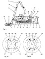
- FIG. 1 schematically illustrated a canister vacuum cleaner, the inventive method, however, in each vacuum cleaner 1, which is equipped with a motor-driven suction fan 2, performed.
- the vacuum cleaner 1 shown has a housing 3 which is divided into a fan chamber 4 and a dust collecting space 5.
- a suction fan 2 is directed with its suction side to the dust collection chamber 5 and generates there a negative pressure, which is passed via a connected suction hose 6 and a suction pipe 7 to the suction mouth of a floor nozzle 8.
- air laden with dirt 9, symbolized by the arrows 10 is absorbed on the processed substrate and cleaned by dust collectors.
- this is a dust bag 11 with downstream motor filter 12 and exhaust filter 13.
- the cleaned air is released again to the environment.
- the control of the in the FIGS. 2a and b Blower motor 14 shown in more detail via a control device, which is formed by the control electronics 15 of an inverter.
- the control electronics 15 switches power semiconductors 16 and is part of a symbolized as a box microprocessor control 17.
- the microprocessor controller 17 also includes an evaluation circuit 18 for detecting the floor covering and is in communication with a in FIG. 3 shown operating and display device 20.
- Flooring sensor for example, have an ultrasonic sensor 19 with appropriate evaluation.
- a switched reluctance motor 141 In the vacuum cleaner shown is a switched reluctance motor 141 (see FIGS. 2a and b ) used.
- the advantage of a switched reluctance motor 141 lies in its simple and robust construction and its wear-free components. It belongs to the group of brushless drives, so has no collector or wear-prone brushes.
- its rotor 142 consists exclusively of iron, so it does not require any electric or permanent magnets in the rotor. For this reason, it is particularly suitable for applications in which high speeds are required, for example for vacuum cleaner fan 2.
- the switched reluctance motor 141 does not generate its torque by the Lorentz force but by reluctance force.
- the function of the machine is based on the fact that air has a very high magnetic reluctance (reluctance) compared to iron material.
- reluctance magnetic reluctance
- the coils 143 of a pole pair of the stator winding are energized, the magnetic flux forced in the stator teeth 144 and 145 closes across the air gap 146 and the rotor 142.
- a reluctance force is imposed which forces the rotor 142 into position the magnetic resistance is as low as possible. This means that most of the magnetic flux goes through the iron material and not through the air.
- this is the position in which the rotor poles 147 and 148 are directly opposite the stator poles 144 and 145 and thus the lowest magnetic resistance is achieved (aligned position) FIG. 2a ), and on the other hand, if two adjacent rotor poles (here the rotor poles 147 and 148) at the same distance to the current stator pole are (unaligned position FIG. 2b ). Between these two positions creates a torque when the coils of the corresponding pole pair 144 and 145 are energized. In order to achieve a continuous rotational movement, the different pole pairs must be switched one after the other depending on the rotor position. For this reason, it is inherently necessary to detect the rotor position of the switched reluctance motor 141.
- the rotor position from switching on to switching off a pair of coils is referred to as a guide area. Within this range the engine generates a torque. With the guidance area, one directly varies the engine torque and ultimately the engine power.
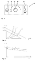
- FIG. 3 the operating and display device 20 is shown. Laterally, an on-off switch 21 and a cable return button 22 are arranged. Centrally there is a rotary switch 23, with the different power levels 24 are set. In addition, the setting of a so-called noise control stage 25 is provided, in which by means of the control electronics 15, the flow generated by the suction fan 2 is influenced as a controlled variable.
- FIG. 4 the dependence of the negative pressure on the flow.
- the aerodynamic operating point of a vacuum cleaner results as the intersection of the fan characteristic curve, a falling straight line, with a parabola which symbolizes the narrowing of the cross section of the air path (load).
- the figure shows three load curves B, C, D with different degrees of narrowing of the airway through flooring of different Flortechnik, the parabola D with the flattest course of a smooth floor, the parabola C corresponds to a carpet with medium Flormaschine and the parabola B a high-pile carpet.
- the blower characteristic A1 can be shifted in parallel by changing the intake power P11 of the vacuum cleaner, A2 shows in dashed lines a blower characteristic at reduced power P12.
- the operating points I, II, III show the operating states in the power P11, the operating points I ', II' and III 'are at a reduced power P12.
- FIGS. 6 and 7 diagrams are shown that are out of the FIG. 4 are similar.
- FIG. 6 shows various blower characteristics A1 to A4.
- three load curves B, C and D are shown, wherein the first load curve B is on a florish carpet (Wilton), the second load curve C on a low - pile carpet (Duracord) and the third load curve D on a smooth floor (parquet, tiles, etc .).
- the noise level of the vacuum cleaner 1 results from the flow, which adjusts itself at the intersection of the blower characteristic with the load characteristic.
- the user For sucking the floor covering Wilton (characteristic B), the user has first set the noise control stage 25 with the rotary switch 23. Now he still actuates the on-off switch 21 and turns on the suction fan 2. The floor nozzle 8 is still lifted off the carpet. It sets a high flow at a correspondingly low speed. The user then places the floor nozzle on the Wilton flooring. The evaluation circuit 18 recognizes due to the size of the speed jump ⁇ n 1 (see FIG. 8 ) that it is Wilton and passes this information to the control electronics 15 on. If present, the type of flooring may alternatively or additionally be determined by the ultrasonic sensor 19.
- the control electronics 15 assigns the flooring of the second category (carpet) and sets a power P11 (blower characteristic A), which is below P1 max (blower characteristic A4).
- the operating point I adjusts itself with a flow rate q ref2 and a certain noise level.
- the noise level is determined inter alia by the flow noise that the vacuum cleaner has on the corresponding floor covering.
- the evaluation circuit 18 detects the flooring type by the size ⁇ n 2 of the speed jump (see FIG. 8 ), who adjusts when changing. Again, alternatively or additionally, the ultrasonic sensor 19 can be used.
- the control electronics 15 also assigns this floor covering to the second category (carpet). At this point, the method according to the invention starts, which adjusts the actual power P11 of the motor 14 so as to adjust the flow rate q ref2 with respect to the operating point I, which is used as the reference value for the desired noise level.
- the power of the motor 14 is reduced by the control electronics 15 to P13 until the operating point II 'is reached on the fan characteristic A3. How out FIG. 6 can be seen, the operating point 12 shifts along the load curve C until the flow q ref2 is obtained, which was present at the operating point I. The noise emission is thus effectively reduced.
- an operating point III which lies at the intersection of the fan characteristic A1 and the load characteristic curve D, is established at an output power P11.
- the control electronics 15 receives the information (speed jump ⁇ n 3 , s. FIG. 8 ), that the currently to be cleaned flooring is a smooth floor covering.
- the control electronics 15 assigns this floor covering to the first category (smooth floor) and specifies a reference flow rate q ref1 . It reduces the power P11 present at operating point III to a power P12, which sets the operating point III '.
- FIG. 7 is a diagram showing the fan characteristics A1 and A2 and the load characteristics B and B 'shows.
- the load curve B refers to the florid flooring Wilton, the bag 6 is empty.
- the load curve B ' refers to the same coating, but the bag is full.
- the operating point I is at the intersection of the load curve B and the blower characteristic A1.
- the operating point I is the flow reference value q ref2 for the noise level to be maintained. If the bag 11 now fills during vacuuming, the load characteristic shifts to B '. With a full bag 11 there is a reduced flow rate q, so that the operating point II is set on the load curve B '.
- the vacuum cleaner 1 tends to be quieter.
- the power In order to reach the reference flow rate q ref2 relative to the operating point I, the power must be increased to P12. It sets an operating point II ', which is above the operating point I and has the same flow q ref2 .
- a substantially constant noise level can be achieved throughout the bag filling.
- the responsive to the bag filling flow control can of course with the illustrated method according to FIG. 6 be combined.
Landscapes
- Engineering & Computer Science (AREA)
- Mechanical Engineering (AREA)
- Electric Vacuum Cleaner (AREA)
Claims (9)
- Procédé de fonctionnement d'un aspirateur (1) avec un ventilateur aspirant (2) qui est entraîné par un moteur de ventilateur électrique (3), et avec un dispositif de régulation (15) qui agit sur le moteur de ventilateur (14) et qui prédéfinit en tant que grandeur de réglage la puissance de moteur (P1, P1 i) ou un paramètre influençant la puissance de moteur (P1, P1i), le débit (q) produit par le ventilateur aspirant (2) étant influencé en tant que grandeur de réglage au moyen du dispositif de régulation,
caractérisé en ce
qu'un circuit d'analyse (18), éventuellement avec utilisation d'un capteur (19), détermine la nature du revêtement de sol à traiter, et en ce que le dispositif de régulation (15) influence, en fonction du revêtement de sol déterminé, la puissance de moteur (P1, P1i) ou le paramètre influençant la puissance de moteur (P1, P1i) de sorte qu'il se manifeste une valeur de débit (qref1) qui est fonction du revêtement de sol. - Procédé de fonctionnement d'un aspirateur (1) selon la revendication 1,
caractérisé en ce que
dispositif de régulation (15) affecte soit à une première catégorie soit à une deuxième catégorie la nature du sol déterminée par le circuit d'analyse (18), et en ce que, en présence de la première catégorie, dispositif de régulation (15) règle une première valeur de débit (qref1) et, en présence de la deuxième catégorie, règle une deuxième valeur de débit (qref2). - Procédé de fonctionnement d'un aspirateur (1) selon la revendication 2,
caractérisé en ce que
la première catégorie comporte essentiellement des sols lisses et la deuxième catégorie comprend essentiellement des tapis, et en ce que la première valeur (qref1) est supérieure à la deuxième valeur (qref2). - Procédé de fonctionnement d'un aspirateur (1) selon l'une des revendications 1 à 3, caractérisé en ce que
le circuit d'analyse (18) détermine la nature du revêtement de sol au moyen d'un capteur de revêtement de sol (19) optique ou acoustique. - Procédé de fonctionnement d'un aspirateur (1) selon l'une des revendications 1 à 3, caractérisé en ce que
le circuit d'analyse (18) détecte la nature d'un premier revêtement de sol par la mesure de la variation de la vitesse de rotation (Δn1) lors du passage du fonctionnement à vide au fonctionnement de nettoyage du premier revêtement de sol. - Procédé de fonctionnement d'un aspirateur (1) selon la revendication 5,
caractérisé en ce que
le circuit d'analyse (18), lors d'un passage du fonctionnement de nettoyage d'un premier revêtement de sol au fonctionnement de nettoyage d'un deuxième revêtement de sol, détecte la nature du deuxième revêtement de sol par la mesure de la variation de la vitesse de rotation (Δn2) lors de ce passage. - Procédé de fonctionnement d'un aspirateur (1) selon au moins une des revendications précédentes,
caractérisé en ce
qu'un moteur universel est utilisé comme moteur de ventilateur (14). - Procédé de fonctionnement d'un aspirateur (1) selon au moins une des revendications 1 à 6,
caractérisé en ce
qu'un moteur à commutation électronique est utilisé comme moteur de ventilateur (14). - Procédé de fonctionnement d'un aspirateur (1) selon la revendication 8,
caractérisé en ce
qu'un moteur à réluctance commutée (141) est utilisé comme moteur de ventilateur (14).
Applications Claiming Priority (1)
| Application Number | Priority Date | Filing Date | Title |
|---|---|---|---|
| DE102007025389A DE102007025389A1 (de) | 2007-05-30 | 2007-05-30 | Verfahren zum Betreiben eines Staubsaugers und Staubsauger zur Durchführung eines solchen Verfahrens |
Publications (3)
| Publication Number | Publication Date |
|---|---|
| EP1997412A2 EP1997412A2 (fr) | 2008-12-03 |
| EP1997412A3 EP1997412A3 (fr) | 2010-01-20 |
| EP1997412B1 true EP1997412B1 (fr) | 2012-10-31 |
Family
ID=39711884
Family Applications (1)
| Application Number | Title | Priority Date | Filing Date |
|---|---|---|---|
| EP08008709A Active EP1997412B1 (fr) | 2007-05-30 | 2008-05-09 | Procédé de fonctionnement d'un aspirateur |
Country Status (2)
| Country | Link |
|---|---|
| EP (1) | EP1997412B1 (fr) |
| DE (1) | DE102007025389A1 (fr) |
Cited By (2)
| Publication number | Priority date | Publication date | Assignee | Title |
|---|---|---|---|---|
| US20220296065A1 (en) * | 2021-03-17 | 2022-09-22 | Talentone Hong Kong Limited | Floor types identifying device, dust suction device having the same, and vacuum cleaner having the same |
| EP4520235A1 (fr) | 2023-09-06 | 2025-03-12 | Alfred Kärcher SE & Co. KG | Aspirateur de nettoyage |
Families Citing this family (18)
| Publication number | Priority date | Publication date | Assignee | Title |
|---|---|---|---|---|
| DE102007011381B3 (de) * | 2007-03-07 | 2008-05-15 | Miele & Cie. Kg | Verfahren zur Erkennung eines Bodenbelages |
| DE102009054490A1 (de) | 2009-12-10 | 2011-06-16 | Poroson Gmbh | Staubsauger |
| DE202009017053U1 (de) | 2009-12-16 | 2010-04-22 | F.E.T. Forschungs- und Entwicklungsgesellschaft für technische Produkte mbH & Co. KG | Staubsaugervorrichtung |
| DE102011006541A1 (de) * | 2011-03-31 | 2012-10-04 | BSH Bosch und Siemens Hausgeräte GmbH | Staubsauger und Verfahren zum saugdruckabhängigen Betreiben eines Staubsaugers |
| DE102011007373A1 (de) | 2011-04-14 | 2012-10-18 | Gerhard Thien | Staubsaugervorrichtung |
| DE102011052020A1 (de) * | 2011-07-21 | 2013-01-24 | Miele & Cie. Kg | Staubsauger und Verfahren zum Betrieb eines Staubsaugers |
| DE102011052023A1 (de) * | 2011-07-21 | 2013-01-24 | Miele & Cie. Kg | Verfahren zur Füllstandsüberwachung bei einem Staubsauger |
| EP3072430B1 (fr) | 2012-03-22 | 2017-05-10 | Eurofilters Holding N.V. | Dispositif destiné à aspirer à l'aide d'un aspirateur et d'un sac filtrant |
| DE102012102631A1 (de) | 2012-03-27 | 2013-10-02 | Alfred Kärcher Gmbh & Co. Kg | Verfahren zum Einstellen eines Saugsystems, Verfahren zum Betreiben eines Saugsystems und Saugsystem |
| NL2009662C2 (nl) * | 2012-10-18 | 2014-04-22 | Bosch Gmbh Robert | Deeltjesopvanginrichting en daarmee voorziene verspaningsinrichting. |
| WO2014094834A1 (fr) * | 2012-12-18 | 2014-06-26 | Alfred Kärcher Gmbh & Co. Kg | Appareil de nettoyage de sol automoteur et autoguidé |
| KR102015325B1 (ko) | 2013-01-29 | 2019-08-28 | 삼성전자주식회사 | 청소 로봇 및 그 제어 방법 |
| DE102013205661A1 (de) | 2013-03-28 | 2014-10-02 | BSH Bosch und Siemens Hausgeräte GmbH | Bodenpflegegerät mit Energiesparfunktion |
| DE102013223864A1 (de) | 2013-11-21 | 2015-05-21 | BSH Hausgeräte GmbH | Verfahren zum Betreiben eines Staubsaugers und Staubsauger |
| DE102013224546A1 (de) * | 2013-11-29 | 2015-06-03 | Bayerische Motoren Werke Aktiengesellschaft | Waschutensil für eine Fahrzeughandwäsche |
| DE102015114668A1 (de) * | 2015-09-02 | 2017-03-02 | Alfred Kärcher Gmbh & Co. Kg | Saugvorrichtung und Verfahren zum Betreiben einer Saugvorrichtung |
| DE102015117552B4 (de) * | 2015-10-15 | 2024-04-18 | Vorwerk & Co. Interholding Gmbh | Vorsatzgerät für ein Haushaltsreinigungsgerät und Haushaltsreinigungsgerät |
| DE102018122971A1 (de) * | 2018-09-19 | 2020-03-19 | Miele & Cie. Kg | Verfahren und Vorrichtung zum Betreiben einer Gebläseeinrichtung für ein batteriebetriebenes Reinigungsgerät und Reinigungsgerät |
Family Cites Families (10)
| Publication number | Priority date | Publication date | Assignee | Title |
|---|---|---|---|---|
| DE2032476A1 (de) * | 1970-07-01 | 1972-01-05 | Licentia Gmbh | Staubsauger, dessen Kompressordrehzahl sich selbsttätig an die verschiedenen Arbeitsprozesse anpaßt |
| DE3030059C2 (de) * | 1980-08-08 | 1984-06-07 | Progress-Elektrogeräte Mauz & Pfeiffer GmbH & Co, 7000 Stuttgart | Staubsauger |
| DE3853409T2 (de) * | 1987-12-15 | 1995-07-27 | Hitachi Ltd | Verfahren für den Betrieb eines Staubsaugers. |
| KR920007588B1 (ko) * | 1990-08-29 | 1992-09-08 | 주식회사 금성사 | 자동주행청소기의 카페트 및 계단감지장치 및 방법 |
| DE9217416U1 (de) * | 1992-12-19 | 1993-04-08 | Fa. Fedag, Romanshorn | Reinigungswerkzeug mit angetriebener Bürstenwalze |
| DE69505255T2 (de) * | 1994-07-13 | 1999-05-27 | Moulinex S.A., Paris | Staubsauger mit fuzzy logic steuerung |
| DE4433181C2 (de) | 1994-09-17 | 1999-06-17 | Miele & Cie | Verfahren zur Vermeidung von Überschwingungen bei der automatischen Saugleistungsregelung eines Staubsaugers |
| DE10113105A1 (de) * | 2000-03-17 | 2001-10-04 | Vorwerk Co Interholding | Bodenpflegegerät sowie Verfahren zur Erkennung eines Bodenzustandes bzw. zur Ausrichtung der Verfahrbewegung |
| DE102005044617A1 (de) * | 2004-10-01 | 2006-04-13 | Vorwerk & Co. Interholding Gmbh | Verfahren zum Pflegen und/oder Reinigen eines Bodenbelages sowie Bodenbelag und Bodenpflege- und oder Reinigungsgerät hierzu |
| DE102004050017B4 (de) | 2004-10-13 | 2006-10-26 | Miele & Cie. Kg | Ventil für ein Bodenpflegegerät, insbesondere für einen Staubsauger |
-
2007
- 2007-05-30 DE DE102007025389A patent/DE102007025389A1/de not_active Ceased
-
2008
- 2008-05-09 EP EP08008709A patent/EP1997412B1/fr active Active
Cited By (3)
| Publication number | Priority date | Publication date | Assignee | Title |
|---|---|---|---|---|
| US20220296065A1 (en) * | 2021-03-17 | 2022-09-22 | Talentone Hong Kong Limited | Floor types identifying device, dust suction device having the same, and vacuum cleaner having the same |
| US11882986B2 (en) * | 2021-03-17 | 2024-01-30 | Talentone Hong Kong Limited | Floor types identifying device, dust suction device having the same, and vacuum cleaner having the same |
| EP4520235A1 (fr) | 2023-09-06 | 2025-03-12 | Alfred Kärcher SE & Co. KG | Aspirateur de nettoyage |
Also Published As
| Publication number | Publication date |
|---|---|
| EP1997412A3 (fr) | 2010-01-20 |
| EP1997412A2 (fr) | 2008-12-03 |
| DE102007025389A1 (de) | 2008-12-04 |
Similar Documents
| Publication | Publication Date | Title |
|---|---|---|
| EP1997412B1 (fr) | Procédé de fonctionnement d'un aspirateur | |
| EP1997417A2 (fr) | Procédé destiné au fonctionnement d'un aspirateur | |
| DE69618166T2 (de) | Staubsauger mit leistungsregelung in abhängigkeit der betriebsart einer elektrischen bürste | |
| DE3853409T2 (de) | Verfahren für den Betrieb eines Staubsaugers. | |
| EP2875767B1 (fr) | Procédé destiné au fonctionnement d'un aspirateur et aspirateur | |
| EP2229088B1 (fr) | Procédé pour interpréter un signal de particules, et buse aspirante pour un aspirateur | |
| EP1332020B1 (fr) | Outil a main comportant un dispositif d'aspiration des poussieres | |
| EP2377445B1 (fr) | Aspirateur avec un dispositif de régulation du ventilateur | |
| EP3569124B1 (fr) | Appareil de nettoyage | |
| EP2548491A1 (fr) | Aspirateur et procédé destiné au fonctionnement dýun aspirateur | |
| EP3120744A1 (fr) | Dispositif de commande de nettoyage d'une unite de filtre pour aspirateur | |
| WO2013144149A1 (fr) | Procédé de réglage d'un système d'aspiration, procédé servant à faire fonctionner un système d'aspiration et système d'aspiration | |
| EP2691003B1 (fr) | Procédé pour faire fonctionner un aspirateur en fonction de la pression d'aspiration | |
| DE69505255T2 (de) | Staubsauger mit fuzzy logic steuerung | |
| BE1030175B1 (de) | Staubsauger, vorzugsweise Handstaubsauger | |
| EP3970584A1 (fr) | Aspirateur, de préférence aspirateur à main | |
| EP3235414A1 (fr) | Procédé d'adaptation de puissance d'un aspirateur à batterie | |
| EP2789283A1 (fr) | Appareil d'aspiration et procédé de fonctionnement d'un appareil d'aspiration | |
| EP3821778B1 (fr) | Aspirateur et procédé de fonctionnement d'un aspirateur | |
| EP2468165B1 (fr) | Aspirateur et procédé destiné au fonctionnement de l'aspirateur | |
| DE4137886C2 (de) | Verfahren zur Bürstenwalzensteuerung einer Staubsaugerbodendüse | |
| DE102020214315A1 (de) | Verfahren zum Betreiben eines Staubsaugers sowie Staubsauger | |
| EP4327709B1 (fr) | Aspirateur, de préférence aspirateur à main | |
| DE19602723A1 (de) | Verfahren und Vorrichtung zum Betrieb eines Staubsaugers | |
| WO2025228787A1 (fr) | Procédé de fonctionnement d'un appareil de nettoyage sous vide et appareil de nettoyage sous vide |
Legal Events
| Date | Code | Title | Description |
|---|---|---|---|
| PUAI | Public reference made under article 153(3) epc to a published international application that has entered the european phase |
Free format text: ORIGINAL CODE: 0009012 |
|
| AK | Designated contracting states |
Kind code of ref document: A2 Designated state(s): AT BE BG CH CY CZ DE DK EE ES FI FR GB GR HR HU IE IS IT LI LT LU LV MC MT NL NO PL PT RO SE SI SK TR |
|
| AX | Request for extension of the european patent |
Extension state: AL BA MK RS |
|
| PUAL | Search report despatched |
Free format text: ORIGINAL CODE: 0009013 |
|
| AK | Designated contracting states |
Kind code of ref document: A3 Designated state(s): AT BE BG CH CY CZ DE DK EE ES FI FR GB GR HR HU IE IS IT LI LT LU LV MC MT NL NO PL PT RO SE SI SK TR |
|
| AX | Request for extension of the european patent |
Extension state: AL BA MK RS |
|
| 17P | Request for examination filed |
Effective date: 20100324 |
|
| AKX | Designation fees paid |
Designated state(s): AT BE BG CH CY CZ DE DK EE ES FI FR GB GR HR HU IE IS IT LI LT LU LV MC MT NL NO PL PT RO SE SI SK TR |
|
| GRAP | Despatch of communication of intention to grant a patent |
Free format text: ORIGINAL CODE: EPIDOSNIGR1 |
|
| GRAS | Grant fee paid |
Free format text: ORIGINAL CODE: EPIDOSNIGR3 |
|
| GRAA | (expected) grant |
Free format text: ORIGINAL CODE: 0009210 |
|
| AK | Designated contracting states |
Kind code of ref document: B1 Designated state(s): AT BE BG CH CY CZ DE DK EE ES FI FR GB GR HR HU IE IS IT LI LT LU LV MC MT NL NO PL PT RO SE SI SK TR |
|
| REG | Reference to a national code |
Ref country code: GB Ref legal event code: FG4D Free format text: NOT ENGLISH Ref country code: CH Ref legal event code: EP |
|
| REG | Reference to a national code |
Ref country code: AT Ref legal event code: REF Ref document number: 581541 Country of ref document: AT Kind code of ref document: T Effective date: 20121115 |
|
| REG | Reference to a national code |
Ref country code: IE Ref legal event code: FG4D Free format text: LANGUAGE OF EP DOCUMENT: GERMAN |
|
| REG | Reference to a national code |
Ref country code: DE Ref legal event code: R096 Ref document number: 502008008534 Country of ref document: DE Effective date: 20121227 |
|
| REG | Reference to a national code |
Ref country code: DE Ref legal event code: R084 Ref document number: 502008008534 Country of ref document: DE Effective date: 20121114 |
|
| REG | Reference to a national code |
Ref country code: LT Ref legal event code: MG4D |
|
| REG | Reference to a national code |
Ref country code: NL Ref legal event code: VDEP Effective date: 20121031 |
|
| PG25 | Lapsed in a contracting state [announced via postgrant information from national office to epo] |
Ref country code: ES Free format text: LAPSE BECAUSE OF FAILURE TO SUBMIT A TRANSLATION OF THE DESCRIPTION OR TO PAY THE FEE WITHIN THE PRESCRIBED TIME-LIMIT Effective date: 20130211 Ref country code: FI Free format text: LAPSE BECAUSE OF FAILURE TO SUBMIT A TRANSLATION OF THE DESCRIPTION OR TO PAY THE FEE WITHIN THE PRESCRIBED TIME-LIMIT Effective date: 20121031 Ref country code: NL Free format text: LAPSE BECAUSE OF FAILURE TO SUBMIT A TRANSLATION OF THE DESCRIPTION OR TO PAY THE FEE WITHIN THE PRESCRIBED TIME-LIMIT Effective date: 20121031 Ref country code: LT Free format text: LAPSE BECAUSE OF FAILURE TO SUBMIT A TRANSLATION OF THE DESCRIPTION OR TO PAY THE FEE WITHIN THE PRESCRIBED TIME-LIMIT Effective date: 20121031 Ref country code: NO Free format text: LAPSE BECAUSE OF FAILURE TO SUBMIT A TRANSLATION OF THE DESCRIPTION OR TO PAY THE FEE WITHIN THE PRESCRIBED TIME-LIMIT Effective date: 20130131 Ref country code: IS Free format text: LAPSE BECAUSE OF FAILURE TO SUBMIT A TRANSLATION OF THE DESCRIPTION OR TO PAY THE FEE WITHIN THE PRESCRIBED TIME-LIMIT Effective date: 20130228 Ref country code: HR Free format text: LAPSE BECAUSE OF FAILURE TO SUBMIT A TRANSLATION OF THE DESCRIPTION OR TO PAY THE FEE WITHIN THE PRESCRIBED TIME-LIMIT Effective date: 20121031 Ref country code: SE Free format text: LAPSE BECAUSE OF FAILURE TO SUBMIT A TRANSLATION OF THE DESCRIPTION OR TO PAY THE FEE WITHIN THE PRESCRIBED TIME-LIMIT Effective date: 20121031 |
|
| PG25 | Lapsed in a contracting state [announced via postgrant information from national office to epo] |
Ref country code: PT Free format text: LAPSE BECAUSE OF FAILURE TO SUBMIT A TRANSLATION OF THE DESCRIPTION OR TO PAY THE FEE WITHIN THE PRESCRIBED TIME-LIMIT Effective date: 20130228 Ref country code: CY Free format text: LAPSE BECAUSE OF FAILURE TO SUBMIT A TRANSLATION OF THE DESCRIPTION OR TO PAY THE FEE WITHIN THE PRESCRIBED TIME-LIMIT Effective date: 20121031 Ref country code: GR Free format text: LAPSE BECAUSE OF FAILURE TO SUBMIT A TRANSLATION OF THE DESCRIPTION OR TO PAY THE FEE WITHIN THE PRESCRIBED TIME-LIMIT Effective date: 20130201 Ref country code: SI Free format text: LAPSE BECAUSE OF FAILURE TO SUBMIT A TRANSLATION OF THE DESCRIPTION OR TO PAY THE FEE WITHIN THE PRESCRIBED TIME-LIMIT Effective date: 20121031 Ref country code: LV Free format text: LAPSE BECAUSE OF FAILURE TO SUBMIT A TRANSLATION OF THE DESCRIPTION OR TO PAY THE FEE WITHIN THE PRESCRIBED TIME-LIMIT Effective date: 20121031 Ref country code: PL Free format text: LAPSE BECAUSE OF FAILURE TO SUBMIT A TRANSLATION OF THE DESCRIPTION OR TO PAY THE FEE WITHIN THE PRESCRIBED TIME-LIMIT Effective date: 20121031 |
|
| PG25 | Lapsed in a contracting state [announced via postgrant information from national office to epo] |
Ref country code: EE Free format text: LAPSE BECAUSE OF FAILURE TO SUBMIT A TRANSLATION OF THE DESCRIPTION OR TO PAY THE FEE WITHIN THE PRESCRIBED TIME-LIMIT Effective date: 20121031 Ref country code: SK Free format text: LAPSE BECAUSE OF FAILURE TO SUBMIT A TRANSLATION OF THE DESCRIPTION OR TO PAY THE FEE WITHIN THE PRESCRIBED TIME-LIMIT Effective date: 20121031 Ref country code: CZ Free format text: LAPSE BECAUSE OF FAILURE TO SUBMIT A TRANSLATION OF THE DESCRIPTION OR TO PAY THE FEE WITHIN THE PRESCRIBED TIME-LIMIT Effective date: 20121031 Ref country code: DK Free format text: LAPSE BECAUSE OF FAILURE TO SUBMIT A TRANSLATION OF THE DESCRIPTION OR TO PAY THE FEE WITHIN THE PRESCRIBED TIME-LIMIT Effective date: 20121031 Ref country code: BG Free format text: LAPSE BECAUSE OF FAILURE TO SUBMIT A TRANSLATION OF THE DESCRIPTION OR TO PAY THE FEE WITHIN THE PRESCRIBED TIME-LIMIT Effective date: 20130131 |
|
| PLBI | Opposition filed |
Free format text: ORIGINAL CODE: 0009260 |
|
| PG25 | Lapsed in a contracting state [announced via postgrant information from national office to epo] |
Ref country code: RO Free format text: LAPSE BECAUSE OF FAILURE TO SUBMIT A TRANSLATION OF THE DESCRIPTION OR TO PAY THE FEE WITHIN THE PRESCRIBED TIME-LIMIT Effective date: 20121031 |
|
| PLAX | Notice of opposition and request to file observation + time limit sent |
Free format text: ORIGINAL CODE: EPIDOSNOBS2 |
|
| 26 | Opposition filed |
Opponent name: BSH BOSCH UND SIEMENS HAUSGERAETE GMBH Effective date: 20130730 |
|
| REG | Reference to a national code |
Ref country code: DE Ref legal event code: R026 Ref document number: 502008008534 Country of ref document: DE Effective date: 20130730 |
|
| REG | Reference to a national code |
Ref country code: HU Ref legal event code: AG4A Ref document number: E017103 Country of ref document: HU |
|
| PLBB | Reply of patent proprietor to notice(s) of opposition received |
Free format text: ORIGINAL CODE: EPIDOSNOBS3 |
|
| BERE | Be: lapsed |
Owner name: MIELE & CIE. K.G. Effective date: 20130531 |
|
| PG25 | Lapsed in a contracting state [announced via postgrant information from national office to epo] |
Ref country code: MC Free format text: LAPSE BECAUSE OF FAILURE TO SUBMIT A TRANSLATION OF THE DESCRIPTION OR TO PAY THE FEE WITHIN THE PRESCRIBED TIME-LIMIT Effective date: 20121031 |
|
| REG | Reference to a national code |
Ref country code: CH Ref legal event code: PL |
|
| GBPC | Gb: european patent ceased through non-payment of renewal fee |
Effective date: 20130509 |
|
| PG25 | Lapsed in a contracting state [announced via postgrant information from national office to epo] |
Ref country code: CH Free format text: LAPSE BECAUSE OF NON-PAYMENT OF DUE FEES Effective date: 20130531 Ref country code: LI Free format text: LAPSE BECAUSE OF NON-PAYMENT OF DUE FEES Effective date: 20130531 |
|
| REG | Reference to a national code |
Ref country code: IE Ref legal event code: MM4A |
|
| PG25 | Lapsed in a contracting state [announced via postgrant information from national office to epo] |
Ref country code: BE Free format text: LAPSE BECAUSE OF NON-PAYMENT OF DUE FEES Effective date: 20130531 |
|
| PG25 | Lapsed in a contracting state [announced via postgrant information from national office to epo] |
Ref country code: GB Free format text: LAPSE BECAUSE OF NON-PAYMENT OF DUE FEES Effective date: 20130509 Ref country code: IE Free format text: LAPSE BECAUSE OF NON-PAYMENT OF DUE FEES Effective date: 20130509 |
|
| REG | Reference to a national code |
Ref country code: AT Ref legal event code: MM01 Ref document number: 581541 Country of ref document: AT Kind code of ref document: T Effective date: 20130509 |
|
| PG25 | Lapsed in a contracting state [announced via postgrant information from national office to epo] |
Ref country code: AT Free format text: LAPSE BECAUSE OF NON-PAYMENT OF DUE FEES Effective date: 20130509 |
|
| PG25 | Lapsed in a contracting state [announced via postgrant information from national office to epo] |
Ref country code: MT Free format text: LAPSE BECAUSE OF FAILURE TO SUBMIT A TRANSLATION OF THE DESCRIPTION OR TO PAY THE FEE WITHIN THE PRESCRIBED TIME-LIMIT Effective date: 20121031 |
|
| REG | Reference to a national code |
Ref country code: FR Ref legal event code: PLFP Year of fee payment: 8 |
|
| PLAB | Opposition data, opponent's data or that of the opponent's representative modified |
Free format text: ORIGINAL CODE: 0009299OPPO |
|
| PG25 | Lapsed in a contracting state [announced via postgrant information from national office to epo] |
Ref country code: TR Free format text: LAPSE BECAUSE OF FAILURE TO SUBMIT A TRANSLATION OF THE DESCRIPTION OR TO PAY THE FEE WITHIN THE PRESCRIBED TIME-LIMIT Effective date: 20121031 |
|
| R26 | Opposition filed (corrected) |
Opponent name: BSH HAUSGERAETE GMBH Effective date: 20130730 |
|
| PG25 | Lapsed in a contracting state [announced via postgrant information from national office to epo] |
Ref country code: LU Free format text: LAPSE BECAUSE OF NON-PAYMENT OF DUE FEES Effective date: 20130509 |
|
| PLCK | Communication despatched that opposition was rejected |
Free format text: ORIGINAL CODE: EPIDOSNREJ1 |
|
| PGFP | Annual fee paid to national office [announced via postgrant information from national office to epo] |
Ref country code: IT Payment date: 20150519 Year of fee payment: 8 Ref country code: HU Payment date: 20150428 Year of fee payment: 8 Ref country code: FR Payment date: 20150519 Year of fee payment: 8 |
|
| APBM | Appeal reference recorded |
Free format text: ORIGINAL CODE: EPIDOSNREFNO |
|
| APBP | Date of receipt of notice of appeal recorded |
Free format text: ORIGINAL CODE: EPIDOSNNOA2O |
|
| APAH | Appeal reference modified |
Free format text: ORIGINAL CODE: EPIDOSCREFNO |
|
| APAJ | Date of receipt of notice of appeal modified |
Free format text: ORIGINAL CODE: EPIDOSCNOA2O |
|
| APBQ | Date of receipt of statement of grounds of appeal recorded |
Free format text: ORIGINAL CODE: EPIDOSNNOA3O |
|
| REG | Reference to a national code |
Ref country code: DE Ref legal event code: R100 Ref document number: 502008008534 Country of ref document: DE |
|
| APBU | Appeal procedure closed |
Free format text: ORIGINAL CODE: EPIDOSNNOA9O |
|
| PLBN | Opposition rejected |
Free format text: ORIGINAL CODE: 0009273 |
|
| STAA | Information on the status of an ep patent application or granted ep patent |
Free format text: STATUS: OPPOSITION REJECTED |
|
| 27O | Opposition rejected |
Effective date: 20160114 |
|
| PG25 | Lapsed in a contracting state [announced via postgrant information from national office to epo] |
Ref country code: IT Free format text: LAPSE BECAUSE OF NON-PAYMENT OF DUE FEES Effective date: 20160509 |
|
| REG | Reference to a national code |
Ref country code: FR Ref legal event code: ST Effective date: 20170131 |
|
| PG25 | Lapsed in a contracting state [announced via postgrant information from national office to epo] |
Ref country code: HU Free format text: LAPSE BECAUSE OF NON-PAYMENT OF DUE FEES Effective date: 20160510 Ref country code: FR Free format text: LAPSE BECAUSE OF NON-PAYMENT OF DUE FEES Effective date: 20160531 |
|
| P01 | Opt-out of the competence of the unified patent court (upc) registered |
Effective date: 20230529 |
|
| PGFP | Annual fee paid to national office [announced via postgrant information from national office to epo] |
Ref country code: DE Payment date: 20250531 Year of fee payment: 18 |