EP2548491A1 - Aspirateur et procédé destiné au fonctionnement dýun aspirateur - Google Patents
Aspirateur et procédé destiné au fonctionnement dýun aspirateur Download PDFInfo
- Publication number
- EP2548491A1 EP2548491A1 EP12401158A EP12401158A EP2548491A1 EP 2548491 A1 EP2548491 A1 EP 2548491A1 EP 12401158 A EP12401158 A EP 12401158A EP 12401158 A EP12401158 A EP 12401158A EP 2548491 A1 EP2548491 A1 EP 2548491A1
- Authority
- EP
- European Patent Office
- Prior art keywords
- drive unit
- volume flow
- vacuum cleaner
- detected
- limit
- Prior art date
- Legal status (The legal status is an assumption and is not a legal conclusion. Google has not performed a legal analysis and makes no representation as to the accuracy of the status listed.)
- Granted
Links
Images


Classifications
-
- A—HUMAN NECESSITIES
- A47—FURNITURE; DOMESTIC ARTICLES OR APPLIANCES; COFFEE MILLS; SPICE MILLS; SUCTION CLEANERS IN GENERAL
- A47L—DOMESTIC WASHING OR CLEANING; SUCTION CLEANERS IN GENERAL
- A47L9/00—Details or accessories of suction cleaners, e.g. mechanical means for controlling the suction or for effecting pulsating action; Storing devices specially adapted to suction cleaners or parts thereof; Carrying-vehicles specially adapted for suction cleaners
- A47L9/28—Installation of the electric equipment, e.g. adaptation or attachment to the suction cleaner; Controlling suction cleaners by electric means
- A47L9/2805—Parameters or conditions being sensed
- A47L9/2821—Pressure, vacuum level or airflow
-
- A—HUMAN NECESSITIES
- A47—FURNITURE; DOMESTIC ARTICLES OR APPLIANCES; COFFEE MILLS; SPICE MILLS; SUCTION CLEANERS IN GENERAL
- A47L—DOMESTIC WASHING OR CLEANING; SUCTION CLEANERS IN GENERAL
- A47L9/00—Details or accessories of suction cleaners, e.g. mechanical means for controlling the suction or for effecting pulsating action; Storing devices specially adapted to suction cleaners or parts thereof; Carrying-vehicles specially adapted for suction cleaners
- A47L9/28—Installation of the electric equipment, e.g. adaptation or attachment to the suction cleaner; Controlling suction cleaners by electric means
- A47L9/2836—Installation of the electric equipment, e.g. adaptation or attachment to the suction cleaner; Controlling suction cleaners by electric means characterised by the parts which are controlled
- A47L9/2842—Suction motors or blowers
Definitions
- the invention relates to a vacuum cleaner and a method for operating a vacuum cleaner.
- Vacuum cleaners are known per se and are operated with electric power either from a mains network or from an entrained voltage source, namely an accumulator or the like.
- Vacuum cleaners remove a comparatively high electrical power from the respective voltage source and convert it into an air or suction power at a floor nozzle or a suction pipe.
- the suction power results as a product of negative pressure on the one hand and volume flow or flow on the other.
- During the suction process results with attached floor nozzle a preferred work area with good efficiency, ie a good ratio of absorbed electrical power and emitted suction, about half of the maximum possible flow rate.
- the floor nozzle or the suction tube end is removed from the floor and set aside to remove e.g. Moving furniture, moving the vacuum cleaner or even going to another room, picking up a phone call, or just to stop sucking.
- the vacuum cleaner is not switched off by the user, but continues with maximum flow, but without suction, on. From an energetic point of view is particularly unfavorable that in this situation, the maximum power is taken from the power source, but no suction power at the floor nozzle is available and is not needed. In addition, there is the fact that the usual noise of a vacuum cleaner continues throughout the period of non-use.
- the JP 2 243 125 A wants to recognize the situation of use by means of movements of the floor nozzle and proposes to detect the movement of the floor nozzle by means of a motion sensor acting as a sensor that detects a rotation of a wheel of the floor nozzle. If a standstill of the floor nozzle is sensed in this way for more than a predetermined period of time, this should be usable for switching off the suction fan.
- the US 2010/0 281 646 A describes an operating method for a specific type of vacuum cleaner, namely a so-called upright vacuum cleaner, in which the use situation is to be detected by means of a tilt sensor, so that the suction fan is supplied to a greater extent electrical power when the device is tilted, because of a continued use is closed and the power supply is reduced when the device is in an upright position.
- An operating method for a vacuum cleaner which aims at a uniform noise development. It is provided that by means of a control device, the volume flow generated by the suction fan is influenced as a control variable. However, a measurement of the volume flow generated in each case is not required and the volume flow is therefore not known. Instead, empirical values can be used, according to which the volume flow is dependent on the respective floor covering and, for example, is higher on smooth floors than on carpet floors. On this basis, it is sufficient if the control device information is transmitted to the respective floor covering, so that instead of a volume flow sensor not required here, a floor covering sensor can occur.
- An operating method for a vacuum cleaner is known in which exactly one pressure sensor detects the static pressure generated by the suction fan. When increasing the detected static pressure, the suction blower output is increased to increase the volume flow. The increase in suction fan power is canceled again when the detected static pressure falls below a threshold.
- the DE 689 16 607 T In order to avoid vibrations, it proposes that the threshold value at which the increase in the suction blower power is reduced is below the threshold value at which the increase in the suction blower power was previously caused.
- An object of the invention is to provide a vacuum cleaner and a method for operating a vacuum cleaner, in which a non-use situation is reliably detected, and so unnecessarily high energy consumption by the drive unit of the suction fan and further associated with the operation of the suction fan noise during the period the non-use is avoided.
- a vacuum cleaner with a drive unit and a drive unit control wherein the drive unit generates a volume flow and a negative pressure in operation of the vacuum cleaner due to supplied electrical power
- the vacuum cleaner means for detecting a measure of the volume flow generated during operation and means for Detecting a measure of the negative pressure generated during operation includes.
- the phrase "to capture a measure” is sometimes omitted in the following for the sake of better readability in determining a measure of a particular size. It will be understood by those skilled in the art that equivalent solutions will result if a particular size is not immediately detectable, but a measure of the particular size is detectable and, instead, that measure is used for the particular size.
- a measure of a volume flow generated during operation or a measure of a negative pressure generated during operation is, for example, a respective proportional or inversely proportional electrical current or voltage.
- detection of a measure for a particular quantity is the acquisition of a respective measured value and the generation and / or transmission of a relevant signal.
- vacuum cleaner is characterized further characterized in that the drive unit control means for forming a calculated value from the detected volume flow and the detected negative pressure, optional means for comparison the detected volumetric flow with a predetermined or predefinable volumetric flow upper limit, but in any case comprises means for comparing the arithmetic variable with a predetermined or predeterminable threshold value as a design limit.
- the floor nozzle removed from the floor is a distinguishing feature for a non-use situation, because, for example, even with a stored suction pipe, the floor nozzle is completely or partially lifted from the ground.
- a raised state of the floor nozzle can be reliably detected.
- a false evaluation is avoided, which is possible, for example, when the increased volume flow results through a new, empty suction bag.
- a ratio of the volume flow to the negative pressure in particular a quotient of the volume flow and the negative pressure, as well as a respective signal or a quotient of the square of the volume flow and the negative pressure (each ratio of the volume flow to the negative pressure, In particular, each quotient formed from the volume flow and negative pressure, so to speak, is a measure of the suction power, because the suction power as a product of the volume flow and the negative pressure results), so that the computational size basically only meaningful in terms of increased flow and a causal lifting the floor nozzle from the ground is.
- the arithmetic quantity formed for example, in the form of a quotient or other ratio of volumetric flow and reduced pressure increases sharply when the maximum volumetric flow for the respective filling level of the anther / dust collecting container of the vacuum cleaner is reached.
- any qualified calculation algorithm which calculates a measure of the volume flow q and a measure of the negative pressure h as input variables comes into consideration for forming the arithmetic variable. Especially good experiences were made with an algorithm based on q * q / h for thresholding.
- the drive unit control also comprises means for reducing the electrical power consumption of the drive unit as a function of both the result of the comparison of the volume flow with the volume flow upper limit and the result of the comparison of the calculated value with the design limit.
- the drive unit control does not itself comprise the means for reducing the electrical power consumption of the drive unit, but controls it.
- the EP 0373 353 A is driven with the exhaust air flow of a suction fan, an air turbine and detects their speed.
- the air turbine acts as a volumetric flow sensor and with a measured value supplied by it, a determination of operating conditions of the vacuum cleaner, for example, the Staubstenhellgrads be possible.
- the EP 0373 353 A also mentions the possibility of combining the volumetric flow measured values supplied by the air turbine with measured values of a diaphragm pressure switch in order to be able to recognize operating states which can not be unambiguously identified solely on the basis of a volumetric flow measured value.
- the EP 0373 353 A But there is no indication of the determination of a suction and there is no linked comparison of flow on the one hand and suction power on the other hand, each with associated comparison values. Furthermore, should at the EP 0373 353 A no reduction in the power consumption of the drive unit done, but it is rather an operating state display can be controlled to indicate, for example, to a level of the dust bag.
- the advantage of the invention is that with the detection of a measure of the volume flow and the detection of a measure of the negative pressure, a direct determination of the relevant parameters for determining the suction power, so that an indirect suction power measurement or at least an indirect determination of a measure of the Suction power, which is attributed to a direct measurement of the relevant parameters.
- the use situation can be easily and reliably detected, especially a non-use situation can be easily detected, because in a non-use situation, the suction decreases immediately drastically and finally disappears.
- the advantage of the invention is further that with the thus ensured improved detection of the non-use situation, an automatic stop function for the vacuum cleaner is realized - by further embodiments, even an automatic start-stop function -which reduces the power consumption when the electric Performance is actually not needed. Accordingly, the approach proposed here is also referred to below as the start-stop function. Furthermore, the reduction in power consumption of the drive unit without renouncing the broader general validity is also referred to below as "switching off" the drive unit, even if this shutdown may not be a complete, but only a partial reduction in power consumption means. Such a shutdown of the vacuum cleaner always means a termination or at least a reduction of the usual noise of the vacuum cleaner.
- the drive unit control means for detecting a duration of exceeding the upper limit of the volume flow through the detected volume flow and means for comparing the duration of the excess with a predetermined or predetermined time limit and as a means for reducing the electrical power consumption depending on Result of comparison of detected duration and time limit activatable signal output includes.
- the stop function is actually activated only when the condition for its activation is fulfilled for a certain period of time, so that e.g. not every brief lifting of the floor nozzle and the concomitant short-term increase in the volume flow leads to an undesired shutdown of the drive unit.
- Sensible values for the time limit are according to the knowledge of the inventor in the order of magnitude of 50 ms to 200 ms.
- the detected volumetric flow is compared with the volumetric flow upper limit, and when the volumetric flow upper limit is exceeded by a duration predetermined by the time limit, activation of the signal output of the drive aggregate control is possible.
- the signal output is only activated if, in addition, the value of the calculated variable formed on the basis of the measured values for negative pressure and volumetric flow exceeds the rated limit.
- the design limit allows consideration of the resistances of the dust bag and the engine and exhaust filters on the one hand and the current power setting for the drive unit on the other.
- the vacuum cleaner has a linking functionality, for example an AND gate or the like, as a means for combining the result of the comparison of the detected duration and time limit on the one hand and the result of the comparison of the calculated value and the design limit on the other hand, an output of this Linking functionality represents the activatable signal output.
- the activatable signal output can then be switched to an actuator to reduce the power consumption of the drive unit and thus cause the "shutdown" of the drive unit in the sense explained above.
- the detection of a decrease in the volume flow or an increase in the negative pressure or a decrease in the volume flow and a simultaneous increase in the negative pressure are expressly independent and at least substantially equivalent criteria for the automatic restart of the drive unit. If only or even the negative pressure is considered, is particularly considered to add sensed pressure changes and deriving from the exceeding of a threshold by the sum thus formed a signal to reactivate the drive unit.
- the drive unit By at rest, ie in connection with the withdrawal of the reduction of the electrical power consumption of the drive unit, the drive unit is at least briefly applied with a respective maximum allowable motor voltage, the performance setting corresponding operating situation of the vacuum cleaner before automatic deactivation can be achieved faster again.
- the automatic stop function or the automatic start-stop function is meaningfully supplemented in that initially and quasi as a stop function of the first degree, the power consumption is reduced, but not yet reduced to zero, and that the reduction of power consumption to zero, so the actual shutdown of the drive unit, only occurs if within a certain time no activation of the drive unit through Further use of the vacuum cleaner takes place (stop function of the second degree).
- the above object is also achieved with a vacuum cleaner which operates according to the method as described here and below and comprises means for carrying out the method.
- the invention is preferably implemented at least partially in software or in software and firmware / hardware.
- the invention is on the one hand also a computer program with executable by a computer program code instructions and on the other hand, a storage medium with such a computer program and finally a control unit in the form of a drive unit control or with such a drive unit control or a vacuum cleaner with such a control unit, in the memory as a means for Implementation of the method and its embodiments such a computer program is loaded or loadable.
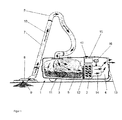
- FIG. 1 schematically shows a simplified vacuum cleaner 1 in one embodiment as a vacuum cleaner.
- the invention is basically suitable for any vacuum cleaner 1, which is equipped with a blower unit with a motor-driven suction fan 2 as a drive unit.
- the vacuum cleaner 1 shown has a housing 3 which is divided into a fan chamber 4 and a dust collecting space 5.
- the suction fan 2 is directed with its suction side to the dust collection chamber 5 and generates there a negative pressure, which is passed through a connected suction hose 6 and a suction pipe 7 to the suction mouth of a floor nozzle 8.
- air laden with dirt 9 - represented by the arrows 10 - is absorbed on the processed substrate (suction air stream) and cleaned by means of a dust separator.
- the cleaned air is discharged through an exhaust filter unit 13 back to the environment.
- the control of a fan motor 14 of the suction fan 2 is carried out in a conventional manner via control electronics of a control unit 15 for controlling, for example power semiconductors of an inverter 16.
- the control unit 15 is an example of a drive unit control or the control unit 15 includes such a drive unit control.
- the fan motor 14 of the suction fan 2 is fed during operation of the vacuum cleaner 1 in a conventional manner with electrical power.
- the suction fan 2 thus generates a negative pressure and finally a volume flow as the basis for the suction air flow.
- an operating and display device 17 is provided for operation and for user information.
- a measure of a volume flow generated during operation in particular analogous values for the actual volume flow q
- various solutions come into consideration: For example, a particular analog differential pressure sensor in the immediate vicinity of the suction fan 2, for example in the range of there usually provided motor protection grille.
- the measured differential pressure between static / dynamic pressure decrease correlates very well with the volume flow q in the measuring range under consideration.
- a Hitz wire a pressure connection to the suction fan 2 or the derivation of the volume flow q from the engine characteristics thinkable and feasible.
- the central suspension of the suction fan or a rubber seal of the suction fan is particularly suitable as a location for the measurement of the volume flow, because there prevail the largest flow velocities.
- a rubber seal of the suction fan is particularly suitable as a location for the measurement of the volume flow, because there prevail the largest flow velocities.
- inject appropriate sensors in the central suspension / rubber seal for example.
- a pressure sensor as a differential pressure sensor against ambient pressure in the region of the inlet opening of the vacuum cleaner 1 into consideration, the pressure in the suction hose 6 or to capture at the entrance of the dust bag 11.
- the negative pressure measured there can still be compensated by the volume flow-dependent pressure drop in the suction hose 6 in order to guarantee a constant suction power at the end of the suction hose 6.
- this would indeed be dispensed with, but it would require additional wiring effort to the floor nozzle 8.
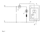
- the in FIG. 2 Drive unit controller 21 shown as a functional unit of the control unit 15, a comparator 22 as a means for comparison the volumetric flow measured value 20 with a predetermined or predeterminable and, for example, stored in a memory 23 volumetric flow upper limit.
- the inverter 16 is actuated via an activatable signal output 24 as a means for reducing the electrical power consumption of the suction fan 2 (drive unit) as an actuator for the drive unit by generating a related control signal.
- a measure of the negative pressure that is, for example, a negative pressure measured value 25
- the in FIG. 2 Drive unit controller 21 shown as a functional unit of the control unit 15 a comparator according to the above-mentioned comparator 22 as a means for comparing the negative pressure measured value 25 with a predetermined or predetermined and for example stored in a memory 23 vacuum lower limit.
- the inverter 16 is actuated via an activatable signal output 24 as means for reducing the electrical power consumption of the suction fan 2 (drive unit) as an actuator for the drive unit by generating a related control signal.
- the implementation of the invention and its embodiments is particularly considered in software or firmware, so that, for example, the comparator 22 as a software or firmware functionality in a control program 30 (FIG. FIG. 3 ) is implemented in the memory 23 of the power plant controller 21.
- the further explanation is continued without abandoning the broader general validity based on the assumption of a software implementation, although in principle a hardware implementation or a combined implementation in software and hardware is conceivable.
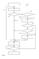
- FIG. 3 shows a flowchart for re-explanation of the principles of the approach according to the invention.
- a processing unit (not shown) in the form of or in the manner of a microprocessor, ASICs or the like by means of the drive unit controller 21, first a measure of a volume flow generated by the vacuum cleaner 1 in operation and / or a measure of the volume flow generated by the vacuum cleaner 1 during operation, on the one hand, and a measure of a vacuum generated by the vacuum cleaner 1 during operation, on the other hand, and a calculated variable from the volume flow and negative pressure as a measure of a suction power (first function block 31).
- a second functional block 32 the detected volume flow with a predefined or predefinable volumetric flow upper limit and / or the arithmetic variable with the prespecified or specifiable as a design limit Threshold compared.
- the electrical power consumption of the drive unit is then possibly reduced by appropriate control of the inverter 16 (third function block 33). Thereafter, unless an abort is caused by its execution, the control program is cyclically continued by re-execution of the first function block 31.
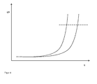
- FIG. 4 shows the course of the calculated size with a first, left curve for a full or at least partially filled dust bag and in a right curve for an empty dust bag.
- the curves are plotted on the abscissa above a respective volumetric flow and on the ordinate over a ratio of volumetric flow and negative pressure. It can be seen that both curves - that is, regardless of the degree of filling of the dust bag - rise sharply for increasing volumetric flow readings.
- the design limit can be drawn as a horizontal line (in FIG. 4 dashed line) and the same numerical value of the design limit can be used for situations with empty, partially filled to full dust bag.
- FIG. 5 shows on the basis of the flowchart in FIG FIG. 3 a particular embodiment of the control program 30, in which it is checked with an intermediate fourth function block 34, whether the detected volume flow exceeds the upper flow limit longer than a predefined or predefinable time limit duration, and the reduction of power consumption by execution of the third function block 33 only at Reaching or exceeding the time limit takes place.
- an arithmetic variable is formed within the first functional block 31, for example a ratio between volumetric flow and negative pressure.
- This variable can be compared, analogously as described above, with a threshold value predetermined or predeterminable as the rated limit, for example within the second functional block 32.
- a reduction of the power consumption of the drive assembly can then take place. This can be done by driving the inverter 16 directly ( FIG. 3, FIG.
- a negative pressure measured value 25 is processed in the form of a variable formed from the volumetric flow measured value 20 and the negative pressure measured value 25 (ratio of the volumetric flow measured value 20 to the negative pressure measured value 25), for example in the form of a quotient of the volumetric flow measured value 20 and the negative pressure measured value 25.
- the calculated size can be formed in basically any form. In the foreground is a sufficient steepness in variations of the volume flow measurement 20 (see FIG. 4 ).
- the respective numerical value of the arithmetic variable can therefore be the result of a mathematical relation, for example as a quotient of the volumetric flow measured value 20 and the negative pressure measured value 25 or as a quotient of the square or higher powers of the volumetric flow measured value 20 and the negative pressure measured value 25, eg q ⁇ n / h ⁇ n , q ⁇ n / h, etc., or an algorithm and the like.
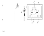
- a corresponding functional unit 26 is provided.
- the arithmetic variable is then compared by a comparator 27 with a predetermined or predetermined threshold value, which is stored, for example in the memory 23 and retrievable there.
- the output signals of the two comparators 22, 27 are logically linked in a suitable manner by a logic unit 28, for example an AND gate, and as a result of this combination, a signal is generated via the activatable signal output 24, depending on the type of connection and input signals for the logic unit 28 generated to drive the inverter 16.
- a logic unit 28 for example an AND gate
- the activatable signal output 24 can thus be activated both as a function of the result of the comparison of the detected duration and time limit value (comparator 22, linking unit 28) and also depending on the result of the comparison of the calculated value with the design limit (functional unit 26, comparator 27, linking unit 28). If - as proposed here - it is provided that both conditions realized by the comparators 22, 27 have to be fulfilled for the reduction of the electrical power consumption of the drive unit, the linking unit 28 is an AND gate or a functionally equivalent unit. If a fulfillment of only one of the conditions is to be sufficient, the linking unit 28 is a corresponding OR gate.
- the branch with the comparator 22 and the combining unit 28 can be dispensed with and the output of the comparator 27 can be applied directly to the activatable signal output 24.
- FIG. 7 shows a further embodiment of the control program 30.
- an effected reduction of the power consumption of the drive unit is detected as the state of the vacuum cleaner 1 by in the cyclic execution of the control program 30 and as long as the conditions expressed by the second and fourth function blocks 32, 34, are always met is branched to the third functional block 33 and thus the control of the inverter 16 is maintained to reduce the power consumption.
- Other ways of detecting such a condition such as by setting a corresponding flag in the control program 30 and interrogating it elsewhere, are also conceivable.
- a possible decrease in the volume flow and / or an increase in the negative pressure is checked by a fifth function block 35 and, depending on the result of this check, if necessary a sixth function block 36 is called up. with the reduction of the electrical power consumption of the drive unit is withdrawn.
- the drive unit in connection with the withdrawal of the reduction of the electrical power consumption of the drive unit, the drive unit is at least briefly acted upon by a respective maximum allowable motor voltage. Furthermore, it can be provided that a duration of the brief application of the drive unit with the respective maximum permissible motor voltage depends on a preselected power position for the drive unit. For example, in memory 23 (FIG. FIG. 2 . FIG. 6 ), a so-called look-up table (LUT) which for each possible power position or a plurality of power value value ranges each includes a time value. This is read out of the memory 23 / the LUT upon activation of the drive unit and used for monitoring the duration of the drive of the drive unit.
- LUT look-up table
- FIG. 3 shows a flowchart for an embodiment of the method or a subsequent drive unit control based on the illustration in FIG. 7 .
- a seventh function block 37 is checked whether the state of reduction of electrical power consumption already longer than a by a predetermined or predetermined threshold value, which is stored for example in the memory 23, expressed time period exists. If this is the case, the drive unit is deactivated and branched to an eighth function block 38, which causes the deactivation of the drive unit.
- a ninth functional block 39 can connect to the eighth functional block 38, with which, for example, a user action, for example a movement of the floor nozzle or the actuation of a push-button of the operating and display device 17, is monitored.
- control program 30th is started with newly initialized starting values with regard to the recorded measured values 20, 25 or the monitored times and the drive unit initially runs as usual until the floor nozzle or the suction pipe is removed from the ground and the stop mechanism or start-stop system described here is started. Automatic to avoid unnecessary energy consumption in the activation state of the drive unit engages.
- a possible by the user or the manufacturer of the vacuum cleaner or customer service calibration of the automatic stop or start-stop automatic is conceivable.
- a calibrating mode intended for calibration would be activated on the vacuum cleaner, for example by actuating a corresponding switching element or by actuating an already existing switching element for more than a predetermined duration.
- the power plant controller indicates the beginning of the calibration by means of a signal emitted by the vacuum cleaner, for example a flashing display device. Then the floor nozzle is lifted and kept in the off position for, for example, at least two seconds. After a predetermined period of time, for example two seconds, the drive unit control detects the volumetric flow measured value 20 and the negative pressure measured value 25. The two measured values recorded are temporarily stored.
- the vacuum Upon completion of the acquisition of these readings, the vacuum will signal the beginning of a second part of the calibration. On such a signal, the floor nozzle is placed and kept for example at least two seconds in the mounted state. After a predetermined period of time, for example two seconds, the drive unit control again detects the volumetric flow measured value 20 and the negative pressure measured value 25. These two measured values are also temporarily stored. From the two cached measured values for the volumetric flow, a new value for the volumetric flow upper limit can be directly derived, for example as the mean value between the two measured values. The new upper flow limit will be in memory, for example a non-volatile memory, the drive unit control stored.
- values for a rated limit can be formed in each case with the values stored temporarily in pairs for the volume flow and negative pressure, and the new rated limit then also results, for example, as the mean value between the two previously formed values.
- the new rated limit is also stored in the memory, for example a non-volatile memory, of the drive unit control.
- the new volume flow upper limit and / or the new rated limit are available as device-specific calibrated or updated limit values.
- Such a calibration helps to identify aging influences and resulting changes in the vacuum and volume flow that can be reached during operation and to adjust the switching conditions for activating the stop or start-stop system. Furthermore, with such a calibration, it is also possible to adapt the switching conditions to different bottom nozzles.
- vacuum cleaner 1 with a drive unit and a drive unit controller 21 and a method for operating such a vacuum cleaner 1, said the drive unit in the operation of the vacuum cleaner 1 due to supplied electrical power generates a volume flow and a negative pressure
- vacuum cleaner 1 and drive unit control 21 are characterized in that the vacuum cleaner 1 comprises means for detecting a measure of the volume flow generated during operation and a measure of the negative pressure generated during operation and the drive unit controller 21 means 22nd for comparing the detected volumetric flow and a predetermined or predefinable volumetric flow upper limit and / or means 27 for comparing a calculated variable formed from the detected volumetric flow and the detected negative pressure with a designation limit or predeterminable threshold, and means 16, 24 for reducing the electrical power consumption depending on the result of the comparison or both comparisons includes or controls.
- an automatic stop function is realized, in further embodiments even an automatic start-stop function.
- the functionality that implements the automatic switch-off and possibly the restarting of the drive unit can be embodied as permanently active functionality or as user-activatable functionality. In the case of a basically permanently active functionality, it can be provided that the functionality can be deactivated by the user.
Landscapes
- Engineering & Computer Science (AREA)
- Mechanical Engineering (AREA)
- Electric Vacuum Cleaner (AREA)
Applications Claiming Priority (1)
| Application Number | Priority Date | Filing Date | Title |
|---|---|---|---|
| DE102011052020A DE102011052020A1 (de) | 2011-07-21 | 2011-07-21 | Staubsauger und Verfahren zum Betrieb eines Staubsaugers |
Publications (2)
| Publication Number | Publication Date |
|---|---|
| EP2548491A1 true EP2548491A1 (fr) | 2013-01-23 |
| EP2548491B1 EP2548491B1 (fr) | 2014-03-19 |
Family
ID=46682776
Family Applications (1)
| Application Number | Title | Priority Date | Filing Date |
|---|---|---|---|
| EP12401158.6A Active EP2548491B1 (fr) | 2011-07-21 | 2012-07-19 | Aspirateur et procédé destiné au fonctionnement dýun aspirateur |
Country Status (3)
| Country | Link |
|---|---|
| US (1) | US9173537B2 (fr) |
| EP (1) | EP2548491B1 (fr) |
| DE (1) | DE102011052020A1 (fr) |
Cited By (1)
| Publication number | Priority date | Publication date | Assignee | Title |
|---|---|---|---|---|
| DE102015114668A1 (de) | 2015-09-02 | 2017-03-02 | Alfred Kärcher Gmbh & Co. Kg | Saugvorrichtung und Verfahren zum Betreiben einer Saugvorrichtung |
Families Citing this family (15)
| Publication number | Priority date | Publication date | Assignee | Title |
|---|---|---|---|---|
| HUE038875T2 (hu) * | 2014-03-20 | 2018-12-28 | Kaercher Gmbh & Co Kg Alfred | Eljárás egy porszívó szûrõjének tisztítására és porszívó |
| US9173533B1 (en) * | 2014-06-25 | 2015-11-03 | Emerson Electric Co. | Upright vacuum cleaner |
| JP6437897B2 (ja) * | 2015-08-10 | 2018-12-12 | アイリスオーヤマ株式会社 | 掃除機 |
| DE102015118648A1 (de) | 2015-10-30 | 2017-05-04 | Vorwerk & Co. Interholding Gmbh | Reinigungsgerät und Verfahren zum Betrieb eines Reinigungsgerätes |
| WO2018000460A1 (fr) * | 2016-06-30 | 2018-01-04 | 江苏美的清洁电器股份有限公司 | Ensemble coupelle à poussière et aspirateur portatif muni de celui-ci |
| JP6692777B2 (ja) * | 2017-07-25 | 2020-05-13 | 株式会社東芝 | 移載装置および判定方法 |
| DE102017117684A1 (de) | 2017-08-03 | 2019-02-07 | Alfred Kärcher SE & Co. KG | Verfahren zum Betreiben eines Sauggeräts und Sauggerät |
| US11440729B2 (en) * | 2019-03-13 | 2022-09-13 | Kenneth Kobane | Vacuuming refuse container assembly |
| DE102019211014B4 (de) * | 2019-07-25 | 2024-07-18 | Vorwerk & Co. Interholding Gmbh | Haushaltsreinigungsgerät mit Akkuantrieb |
| SE544198C2 (en) * | 2019-11-14 | 2022-03-01 | Husqvarna Ab | Improved dust extractor motor control |
| EP3845106A1 (fr) * | 2019-12-30 | 2021-07-07 | Koninklijke Philips N.V. | Pompe à utiliser dans un aspirateur |
| DE102021001064B3 (de) | 2021-02-24 | 2022-05-19 | Pitt Fischer | Modul-Geräte-System zur Pflege der Raumlufthygiene, der Bodenflächenpflege, der Virenbeseitigung dem Luftaustausch, der Luftbefeuchtung und anderer mit einem luftstromerzeugenden Motor arbeitenden Vorrichtungen, nebst Raum- und Raumluftqualitätsüberwachung. |
| FI130712B1 (fi) * | 2021-11-23 | 2024-02-05 | Mirka Ltd | Pölynimuri |
| JP7764496B2 (ja) | 2022-01-11 | 2025-11-05 | ヴェルスニ ホールディング ビー ヴィ | 湿式洗浄装置 |
| KR20240021613A (ko) * | 2022-08-10 | 2024-02-19 | 삼성전자주식회사 | 흡입력을 조정하는 청소기 및 그 제어 방법 |
Citations (7)
| Publication number | Priority date | Publication date | Assignee | Title |
|---|---|---|---|---|
| EP0373353A1 (fr) | 1988-12-16 | 1990-06-20 | Interlava AG | Dispositif de régulation et d'indication de fonctionnement pour aspirateurs de poussières |
| JPH02243125A (ja) | 1989-03-17 | 1990-09-27 | Sanyo Electric Co Ltd | 電気掃除機 |
| DE68916607T2 (de) | 1988-10-07 | 1994-12-01 | Hitachi Ltd | Staubsauger und Verfahren zu dessen Betrieb. |
| US6105202A (en) | 1998-01-30 | 2000-08-22 | Stmicrolectronics S.R.L. | Intelligent suction device capable of automatically adapting the suction force according to the conditions of the surface, particularly for vacuum cleaners and the like |
| WO2002091899A1 (fr) | 2001-05-15 | 2002-11-21 | Arçelik A.S. | Procede de commande d'un aspirateur |
| DE102007025389A1 (de) | 2007-05-30 | 2008-12-04 | Miele & Cie. Kg | Verfahren zum Betreiben eines Staubsaugers und Staubsauger zur Durchführung eines solchen Verfahrens |
| US20100281646A1 (en) | 2006-09-11 | 2010-11-11 | Panasonic Corporation | Electric cleaner |
-
2011
- 2011-07-21 DE DE102011052020A patent/DE102011052020A1/de not_active Ceased
-
2012
- 2012-07-19 US US13/552,814 patent/US9173537B2/en active Active
- 2012-07-19 EP EP12401158.6A patent/EP2548491B1/fr active Active
Patent Citations (7)
| Publication number | Priority date | Publication date | Assignee | Title |
|---|---|---|---|---|
| DE68916607T2 (de) | 1988-10-07 | 1994-12-01 | Hitachi Ltd | Staubsauger und Verfahren zu dessen Betrieb. |
| EP0373353A1 (fr) | 1988-12-16 | 1990-06-20 | Interlava AG | Dispositif de régulation et d'indication de fonctionnement pour aspirateurs de poussières |
| JPH02243125A (ja) | 1989-03-17 | 1990-09-27 | Sanyo Electric Co Ltd | 電気掃除機 |
| US6105202A (en) | 1998-01-30 | 2000-08-22 | Stmicrolectronics S.R.L. | Intelligent suction device capable of automatically adapting the suction force according to the conditions of the surface, particularly for vacuum cleaners and the like |
| WO2002091899A1 (fr) | 2001-05-15 | 2002-11-21 | Arçelik A.S. | Procede de commande d'un aspirateur |
| US20100281646A1 (en) | 2006-09-11 | 2010-11-11 | Panasonic Corporation | Electric cleaner |
| DE102007025389A1 (de) | 2007-05-30 | 2008-12-04 | Miele & Cie. Kg | Verfahren zum Betreiben eines Staubsaugers und Staubsauger zur Durchführung eines solchen Verfahrens |
Cited By (1)
| Publication number | Priority date | Publication date | Assignee | Title |
|---|---|---|---|---|
| DE102015114668A1 (de) | 2015-09-02 | 2017-03-02 | Alfred Kärcher Gmbh & Co. Kg | Saugvorrichtung und Verfahren zum Betreiben einer Saugvorrichtung |
Also Published As
| Publication number | Publication date |
|---|---|
| US9173537B2 (en) | 2015-11-03 |
| DE102011052020A1 (de) | 2013-01-24 |
| US20130019901A1 (en) | 2013-01-24 |
| EP2548491B1 (fr) | 2014-03-19 |
Similar Documents
| Publication | Publication Date | Title |
|---|---|---|
| EP2548491B1 (fr) | Aspirateur et procédé destiné au fonctionnement dýun aspirateur | |
| CN108981079B (zh) | 空调器过滤网积尘检测方法、空调器及存储介质 | |
| EP3119260B1 (fr) | Méthode pour nettoyer un filtre d'un aspirateur et l'aspirateur | |
| EP1967115B1 (fr) | Procédé de reconnaissance d'un revêtement de sol | |
| EP2548490A2 (fr) | Procédé de surveillance du niveau de remplissage d'un aspirateur et aspirateur pour réaliser un tel procédé | |
| EP2543302B1 (fr) | Procédé d'utilisation d'un aspirateur doté d'un séparateur à cyclone et aspirateur doté d'un séparateur à cyclone | |
| WO2009103585A1 (fr) | Dispositif de régulation automatique de la puissance d’aspiration d’un aspirateur | |
| EP3162266B1 (fr) | Appareil de nettoyage et procédé pour utiliser l'appareil de nettoyage | |
| DE102007025389A1 (de) | Verfahren zum Betreiben eines Staubsaugers und Staubsauger zur Durchführung eines solchen Verfahrens | |
| EP2875767B1 (fr) | Procédé destiné au fonctionnement d'un aspirateur et aspirateur | |
| EP3479745B1 (fr) | Procédé de fonctionnement d'un entraînement électrique, de préférence d'un ventilateur et / ou d'une brosse d'un aspirateur ou d'un aspirateur robot | |
| EP3120744B1 (fr) | Dispositif de commande de nettoyage d'une unite de filtre pour aspirateur | |
| DE102007061146A1 (de) | Verfahren zur Auswertung eines Partikelsignals und Saugdüse für einen Staubsauger | |
| EP2595522B1 (fr) | Procédé et dispositif de commande de performance d'un moteur de soufflerie pour un aspirateur | |
| WO2013144149A1 (fr) | Procédé de réglage d'un système d'aspiration, procédé servant à faire fonctionner un système d'aspiration et système d'aspiration | |
| EP2946711B1 (fr) | Procédé de fonctionnement d'un aspirateur et aspirateur | |
| DE102015100353B4 (de) | Verfahren zur Steuerung eines Staubsaugers, Steuereinrichtung für einen Staubsauger und Staubsauger | |
| EP2505115B1 (fr) | Aspirateur et procédé destiné au fonctionnement en fonction de la durée de fonctionnement d'un aspirateur | |
| DE102011050260B4 (de) | Staubsauger und Verfahren zur Auswertung eines Partikelsignals in einem Staubsauger | |
| EP3507409A1 (fr) | Appareil d'entretien du linge doté d'une commande | |
| DE102017112741A1 (de) | Staubsauger mit Objekterkennung und Verfahren zum Betreiben eines Staubsaugers | |
| EP3821778B1 (fr) | Aspirateur et procédé de fonctionnement d'un aspirateur | |
| EP4368087A1 (fr) | Procédé de détermination d'un degré de remplissage d'un récipient à poussière et aspirateur | |
| DE102016206917A1 (de) | Verfahren zur Leistungsanpassung eines akkumulatorbetriebenen Staubsaugers | |
| EP3437535A1 (fr) | Aspirateur |
Legal Events
| Date | Code | Title | Description |
|---|---|---|---|
| PUAI | Public reference made under article 153(3) epc to a published international application that has entered the european phase |
Free format text: ORIGINAL CODE: 0009012 |
|
| 17P | Request for examination filed |
Effective date: 20121115 |
|
| AK | Designated contracting states |
Kind code of ref document: A1 Designated state(s): AL AT BE BG CH CY CZ DE DK EE ES FI FR GB GR HR HU IE IS IT LI LT LU LV MC MK MT NL NO PL PT RO RS SE SI SK SM TR |
|
| AX | Request for extension of the european patent |
Extension state: BA ME |
|
| GRAP | Despatch of communication of intention to grant a patent |
Free format text: ORIGINAL CODE: EPIDOSNIGR1 |
|
| RIC1 | Information provided on ipc code assigned before grant |
Ipc: A47L 9/28 20060101AFI20131105BHEP |
|
| INTG | Intention to grant announced |
Effective date: 20131125 |
|
| GRAS | Grant fee paid |
Free format text: ORIGINAL CODE: EPIDOSNIGR3 |
|
| GRAA | (expected) grant |
Free format text: ORIGINAL CODE: 0009210 |
|
| AK | Designated contracting states |
Kind code of ref document: B1 Designated state(s): AL AT BE BG CH CY CZ DE DK EE ES FI FR GB GR HR HU IE IS IT LI LT LU LV MC MK MT NL NO PL PT RO RS SE SI SK SM TR |
|
| REG | Reference to a national code |
Ref country code: GB Ref legal event code: FG4D Free format text: NOT ENGLISH |
|
| REG | Reference to a national code |
Ref country code: CH Ref legal event code: EP |
|
| REG | Reference to a national code |
Ref country code: DE Ref legal event code: R084 Ref document number: 502012000483 Country of ref document: DE |
|
| REG | Reference to a national code |
Ref country code: AT Ref legal event code: REF Ref document number: 657097 Country of ref document: AT Kind code of ref document: T Effective date: 20140415 |
|
| REG | Reference to a national code |
Ref country code: IE Ref legal event code: FG4D Free format text: LANGUAGE OF EP DOCUMENT: GERMAN |
|
| REG | Reference to a national code |
Ref country code: DE Ref legal event code: R096 Ref document number: 502012000483 Country of ref document: DE Effective date: 20140508 |
|
| REG | Reference to a national code |
Ref country code: DE Ref legal event code: R084 Ref document number: 502012000483 Country of ref document: DE Effective date: 20140404 |
|
| REG | Reference to a national code |
Ref country code: GB Ref legal event code: 746 Effective date: 20140602 |
|
| PG25 | Lapsed in a contracting state [announced via postgrant information from national office to epo] |
Ref country code: NO Free format text: LAPSE BECAUSE OF FAILURE TO SUBMIT A TRANSLATION OF THE DESCRIPTION OR TO PAY THE FEE WITHIN THE PRESCRIBED TIME-LIMIT Effective date: 20140619 Ref country code: LT Free format text: LAPSE BECAUSE OF FAILURE TO SUBMIT A TRANSLATION OF THE DESCRIPTION OR TO PAY THE FEE WITHIN THE PRESCRIBED TIME-LIMIT Effective date: 20140319 |
|
| REG | Reference to a national code |
Ref country code: NL Ref legal event code: VDEP Effective date: 20140319 |
|
| REG | Reference to a national code |
Ref country code: LT Ref legal event code: MG4D |
|
| PG25 | Lapsed in a contracting state [announced via postgrant information from national office to epo] |
Ref country code: SE Free format text: LAPSE BECAUSE OF FAILURE TO SUBMIT A TRANSLATION OF THE DESCRIPTION OR TO PAY THE FEE WITHIN THE PRESCRIBED TIME-LIMIT Effective date: 20140319 Ref country code: CY Free format text: LAPSE BECAUSE OF FAILURE TO SUBMIT A TRANSLATION OF THE DESCRIPTION OR TO PAY THE FEE WITHIN THE PRESCRIBED TIME-LIMIT Effective date: 20140319 Ref country code: FI Free format text: LAPSE BECAUSE OF FAILURE TO SUBMIT A TRANSLATION OF THE DESCRIPTION OR TO PAY THE FEE WITHIN THE PRESCRIBED TIME-LIMIT Effective date: 20140319 |
|
| PG25 | Lapsed in a contracting state [announced via postgrant information from national office to epo] |
Ref country code: LV Free format text: LAPSE BECAUSE OF FAILURE TO SUBMIT A TRANSLATION OF THE DESCRIPTION OR TO PAY THE FEE WITHIN THE PRESCRIBED TIME-LIMIT Effective date: 20140319 Ref country code: RS Free format text: LAPSE BECAUSE OF FAILURE TO SUBMIT A TRANSLATION OF THE DESCRIPTION OR TO PAY THE FEE WITHIN THE PRESCRIBED TIME-LIMIT Effective date: 20140319 Ref country code: HR Free format text: LAPSE BECAUSE OF FAILURE TO SUBMIT A TRANSLATION OF THE DESCRIPTION OR TO PAY THE FEE WITHIN THE PRESCRIBED TIME-LIMIT Effective date: 20140319 |
|
| PG25 | Lapsed in a contracting state [announced via postgrant information from national office to epo] |
Ref country code: CZ Free format text: LAPSE BECAUSE OF FAILURE TO SUBMIT A TRANSLATION OF THE DESCRIPTION OR TO PAY THE FEE WITHIN THE PRESCRIBED TIME-LIMIT Effective date: 20140319 Ref country code: NL Free format text: LAPSE BECAUSE OF FAILURE TO SUBMIT A TRANSLATION OF THE DESCRIPTION OR TO PAY THE FEE WITHIN THE PRESCRIBED TIME-LIMIT Effective date: 20140319 Ref country code: BG Free format text: LAPSE BECAUSE OF FAILURE TO SUBMIT A TRANSLATION OF THE DESCRIPTION OR TO PAY THE FEE WITHIN THE PRESCRIBED TIME-LIMIT Effective date: 20140619 Ref country code: IS Free format text: LAPSE BECAUSE OF FAILURE TO SUBMIT A TRANSLATION OF THE DESCRIPTION OR TO PAY THE FEE WITHIN THE PRESCRIBED TIME-LIMIT Effective date: 20140719 Ref country code: RO Free format text: LAPSE BECAUSE OF FAILURE TO SUBMIT A TRANSLATION OF THE DESCRIPTION OR TO PAY THE FEE WITHIN THE PRESCRIBED TIME-LIMIT Effective date: 20140319 Ref country code: EE Free format text: LAPSE BECAUSE OF FAILURE TO SUBMIT A TRANSLATION OF THE DESCRIPTION OR TO PAY THE FEE WITHIN THE PRESCRIBED TIME-LIMIT Effective date: 20140319 |
|
| PG25 | Lapsed in a contracting state [announced via postgrant information from national office to epo] |
Ref country code: ES Free format text: LAPSE BECAUSE OF FAILURE TO SUBMIT A TRANSLATION OF THE DESCRIPTION OR TO PAY THE FEE WITHIN THE PRESCRIBED TIME-LIMIT Effective date: 20140319 Ref country code: SK Free format text: LAPSE BECAUSE OF FAILURE TO SUBMIT A TRANSLATION OF THE DESCRIPTION OR TO PAY THE FEE WITHIN THE PRESCRIBED TIME-LIMIT Effective date: 20140319 Ref country code: PL Free format text: LAPSE BECAUSE OF FAILURE TO SUBMIT A TRANSLATION OF THE DESCRIPTION OR TO PAY THE FEE WITHIN THE PRESCRIBED TIME-LIMIT Effective date: 20140319 |
|
| REG | Reference to a national code |
Ref country code: DE Ref legal event code: R097 Ref document number: 502012000483 Country of ref document: DE |
|
| REG | Reference to a national code |
Ref country code: HU Ref legal event code: AG4A Ref document number: E021268 Country of ref document: HU |
|
| PG25 | Lapsed in a contracting state [announced via postgrant information from national office to epo] |
Ref country code: PT Free format text: LAPSE BECAUSE OF FAILURE TO SUBMIT A TRANSLATION OF THE DESCRIPTION OR TO PAY THE FEE WITHIN THE PRESCRIBED TIME-LIMIT Effective date: 20140721 |
|
| PLBE | No opposition filed within time limit |
Free format text: ORIGINAL CODE: 0009261 |
|
| STAA | Information on the status of an ep patent application or granted ep patent |
Free format text: STATUS: NO OPPOSITION FILED WITHIN TIME LIMIT |
|
| PG25 | Lapsed in a contracting state [announced via postgrant information from national office to epo] |
Ref country code: DK Free format text: LAPSE BECAUSE OF FAILURE TO SUBMIT A TRANSLATION OF THE DESCRIPTION OR TO PAY THE FEE WITHIN THE PRESCRIBED TIME-LIMIT Effective date: 20140319 |
|
| 26N | No opposition filed |
Effective date: 20141222 |
|
| PG25 | Lapsed in a contracting state [announced via postgrant information from national office to epo] |
Ref country code: LU Free format text: LAPSE BECAUSE OF FAILURE TO SUBMIT A TRANSLATION OF THE DESCRIPTION OR TO PAY THE FEE WITHIN THE PRESCRIBED TIME-LIMIT Effective date: 20140719 |
|
| REG | Reference to a national code |
Ref country code: DE Ref legal event code: R097 Ref document number: 502012000483 Country of ref document: DE Effective date: 20141222 |
|
| REG | Reference to a national code |
Ref country code: IE Ref legal event code: MM4A |
|
| PG25 | Lapsed in a contracting state [announced via postgrant information from national office to epo] |
Ref country code: SI Free format text: LAPSE BECAUSE OF FAILURE TO SUBMIT A TRANSLATION OF THE DESCRIPTION OR TO PAY THE FEE WITHIN THE PRESCRIBED TIME-LIMIT Effective date: 20140319 |
|
| PG25 | Lapsed in a contracting state [announced via postgrant information from national office to epo] |
Ref country code: IE Free format text: LAPSE BECAUSE OF NON-PAYMENT OF DUE FEES Effective date: 20140719 |
|
| REG | Reference to a national code |
Ref country code: CH Ref legal event code: PL |
|
| PG25 | Lapsed in a contracting state [announced via postgrant information from national office to epo] |
Ref country code: LI Free format text: LAPSE BECAUSE OF NON-PAYMENT OF DUE FEES Effective date: 20150731 Ref country code: CH Free format text: LAPSE BECAUSE OF NON-PAYMENT OF DUE FEES Effective date: 20150731 Ref country code: MC Free format text: LAPSE BECAUSE OF FAILURE TO SUBMIT A TRANSLATION OF THE DESCRIPTION OR TO PAY THE FEE WITHIN THE PRESCRIBED TIME-LIMIT Effective date: 20140319 Ref country code: SM Free format text: LAPSE BECAUSE OF FAILURE TO SUBMIT A TRANSLATION OF THE DESCRIPTION OR TO PAY THE FEE WITHIN THE PRESCRIBED TIME-LIMIT Effective date: 20140319 |
|
| PG25 | Lapsed in a contracting state [announced via postgrant information from national office to epo] |
Ref country code: MT Free format text: LAPSE BECAUSE OF FAILURE TO SUBMIT A TRANSLATION OF THE DESCRIPTION OR TO PAY THE FEE WITHIN THE PRESCRIBED TIME-LIMIT Effective date: 20140319 Ref country code: GR Free format text: LAPSE BECAUSE OF FAILURE TO SUBMIT A TRANSLATION OF THE DESCRIPTION OR TO PAY THE FEE WITHIN THE PRESCRIBED TIME-LIMIT Effective date: 20140620 |
|
| REG | Reference to a national code |
Ref country code: FR Ref legal event code: PLFP Year of fee payment: 5 |
|
| PG25 | Lapsed in a contracting state [announced via postgrant information from national office to epo] |
Ref country code: BE Free format text: LAPSE BECAUSE OF FAILURE TO SUBMIT A TRANSLATION OF THE DESCRIPTION OR TO PAY THE FEE WITHIN THE PRESCRIBED TIME-LIMIT Effective date: 20140731 Ref country code: TR Free format text: LAPSE BECAUSE OF FAILURE TO SUBMIT A TRANSLATION OF THE DESCRIPTION OR TO PAY THE FEE WITHIN THE PRESCRIBED TIME-LIMIT Effective date: 20140319 |
|
| REG | Reference to a national code |
Ref country code: FR Ref legal event code: PLFP Year of fee payment: 6 |
|
| REG | Reference to a national code |
Ref country code: HU Ref legal event code: HC9C |
|
| PG25 | Lapsed in a contracting state [announced via postgrant information from national office to epo] |
Ref country code: MK Free format text: LAPSE BECAUSE OF FAILURE TO SUBMIT A TRANSLATION OF THE DESCRIPTION OR TO PAY THE FEE WITHIN THE PRESCRIBED TIME-LIMIT Effective date: 20140319 |
|
| REG | Reference to a national code |
Ref country code: FR Ref legal event code: PLFP Year of fee payment: 7 |
|
| REG | Reference to a national code |
Ref country code: AT Ref legal event code: MM01 Ref document number: 657097 Country of ref document: AT Kind code of ref document: T Effective date: 20170719 |
|
| PG25 | Lapsed in a contracting state [announced via postgrant information from national office to epo] |
Ref country code: AL Free format text: LAPSE BECAUSE OF FAILURE TO SUBMIT A TRANSLATION OF THE DESCRIPTION OR TO PAY THE FEE WITHIN THE PRESCRIBED TIME-LIMIT Effective date: 20140319 |
|
| PG25 | Lapsed in a contracting state [announced via postgrant information from national office to epo] |
Ref country code: AT Free format text: LAPSE BECAUSE OF NON-PAYMENT OF DUE FEES Effective date: 20170719 |
|
| PGFP | Annual fee paid to national office [announced via postgrant information from national office to epo] |
Ref country code: HU Payment date: 20180829 Year of fee payment: 7 |
|
| PG25 | Lapsed in a contracting state [announced via postgrant information from national office to epo] |
Ref country code: HU Free format text: LAPSE BECAUSE OF NON-PAYMENT OF DUE FEES Effective date: 20190720 |
|
| P01 | Opt-out of the competence of the unified patent court (upc) registered |
Effective date: 20230529 |
|
| PGFP | Annual fee paid to national office [announced via postgrant information from national office to epo] |
Ref country code: IT Payment date: 20230721 Year of fee payment: 12 |
|
| PG25 | Lapsed in a contracting state [announced via postgrant information from national office to epo] |
Ref country code: IT Free format text: LAPSE BECAUSE OF NON-PAYMENT OF DUE FEES Effective date: 20240719 |
|
| PGFP | Annual fee paid to national office [announced via postgrant information from national office to epo] |
Ref country code: DE Payment date: 20250731 Year of fee payment: 14 |
|
| PGFP | Annual fee paid to national office [announced via postgrant information from national office to epo] |
Ref country code: GB Payment date: 20250722 Year of fee payment: 14 |
|
| PGFP | Annual fee paid to national office [announced via postgrant information from national office to epo] |
Ref country code: FR Payment date: 20250725 Year of fee payment: 14 |