EP1997597B1 - Appareil et procédé pour appliquer un bord de protection et panneau composite avec des bords - Google Patents
Appareil et procédé pour appliquer un bord de protection et panneau composite avec des bords Download PDFInfo
- Publication number
- EP1997597B1 EP1997597B1 EP08156526.9A EP08156526A EP1997597B1 EP 1997597 B1 EP1997597 B1 EP 1997597B1 EP 08156526 A EP08156526 A EP 08156526A EP 1997597 B1 EP1997597 B1 EP 1997597B1
- Authority
- EP
- European Patent Office
- Prior art keywords
- tool
- pressing element
- axis
- axial
- panel
- Prior art date
- Legal status (The legal status is an assumption and is not a legal conclusion. Google has not performed a legal analysis and makes no representation as to the accuracy of the status listed.)
- Active
Links
Images
Classifications
-
- E—FIXED CONSTRUCTIONS
- E04—BUILDING
- E04C—STRUCTURAL ELEMENTS; BUILDING MATERIALS
- E04C2/00—Building elements of relatively thin form for the construction of parts of buildings, e.g. sheet materials, slabs, or panels
- E04C2/30—Building elements of relatively thin form for the construction of parts of buildings, e.g. sheet materials, slabs, or panels characterised by the shape or structure
- E04C2/34—Building elements of relatively thin form for the construction of parts of buildings, e.g. sheet materials, slabs, or panels characterised by the shape or structure composed of two or more spaced sheet-like parts
- E04C2/36—Building elements of relatively thin form for the construction of parts of buildings, e.g. sheet materials, slabs, or panels characterised by the shape or structure composed of two or more spaced sheet-like parts spaced apart by transversely-placed strip material, e.g. honeycomb panels
- E04C2/365—Building elements of relatively thin form for the construction of parts of buildings, e.g. sheet materials, slabs, or panels characterised by the shape or structure composed of two or more spaced sheet-like parts spaced apart by transversely-placed strip material, e.g. honeycomb panels by honeycomb structures
-
- B—PERFORMING OPERATIONS; TRANSPORTING
- B27—WORKING OR PRESERVING WOOD OR SIMILAR MATERIAL; NAILING OR STAPLING MACHINES IN GENERAL
- B27D—WORKING VENEER OR PLYWOOD
- B27D1/00—Joining wood veneer with any material; Forming articles thereby; Preparatory processing of surfaces to be joined, e.g. scoring
- B27D1/04—Joining wood veneer with any material; Forming articles thereby; Preparatory processing of surfaces to be joined, e.g. scoring to produce plywood or articles made therefrom; Plywood sheets
- B27D1/06—Manufacture of central layers; Form of central layers
-
- B—PERFORMING OPERATIONS; TRANSPORTING
- B27—WORKING OR PRESERVING WOOD OR SIMILAR MATERIAL; NAILING OR STAPLING MACHINES IN GENERAL
- B27D—WORKING VENEER OR PLYWOOD
- B27D5/00—Other working of veneer or plywood specially adapted to veneer or plywood
- B27D5/006—Trimming, chamfering or bevelling edgings, e.g. lists
-
- B—PERFORMING OPERATIONS; TRANSPORTING
- B29—WORKING OF PLASTICS; WORKING OF SUBSTANCES IN A PLASTIC STATE IN GENERAL
- B29C—SHAPING OR JOINING OF PLASTICS; SHAPING OF MATERIAL IN A PLASTIC STATE, NOT OTHERWISE PROVIDED FOR; AFTER-TREATMENT OF THE SHAPED PRODUCTS, e.g. REPAIRING
- B29C63/00—Lining or sheathing, i.e. applying preformed layers or sheathings of plastics; Apparatus therefor
- B29C63/0026—Lining or sheathing, i.e. applying preformed layers or sheathings of plastics; Apparatus therefor an edge face with strip material, e.g. a panel edge
- B29C63/003—Lining or sheathing, i.e. applying preformed layers or sheathings of plastics; Apparatus therefor an edge face with strip material, e.g. a panel edge continuously
Definitions
- the invention substantially relates to a tool according to the preamble of claim 1 and a method for edge-banding a panel according to the preamble of claim 15.
- a tool and such a method are known from document GB1249097A .
- This type of panel used for making furniture in general, doors, or other furnishing elements, has an inner structure that is generally made of cardboard, whilst the laminar elements can be made of plastics, wood or the like.
- Apparatuses are known comprising a cutting tool, generally a milling cutter, which is driven so as to run along the edge of a panel to be edge-banded so as to remove a part of the honeycomb structure and obtain a groove in which a supporting strip is subsequently glued that provides an externally smooth and continuous surface onto which a finishing strip can be glued.
- the supporting strip has to be applied to the panel inasmuch as the internal honeycomb structure is not in itself suitable for receiving the finishing strip in a stable manner.
- a drawback of apparatuses of known type is that they force both the supporting strip and the finishing strip to be applied, which entails a certain degree of machining complexity and requires expensive equipment.
- GB1249097A discloses a milling device for removing the projecting longitudinal edges of strip material which has been secured to the peripheral surfaces of flat workpieces.
- US5433563A describes a tool for preparing a substrate edge of a counter-top to accept a moulded apron having at least two perpendicular appendages.
- the tool includes cutters for cutting a channel and/or a rabbet into the substrate edge. The spacing between the cutting edges of the cutters corresponds to a spacing between the perpendicular appendages of the moulded apron.
- An object of the invention is to improve edge-banding of panels.
- Another object is to simplify edge-banding of panels, in particular having a honeycomb structure.
- a further object is to make panel available that has a simpler and less costly structure
- an apparatus is provided as defined in claim 1.
- the finishing strip can be applied directly to the compacted outer surface of the honeycomb structure.
- the pressing element It is important for the pressing element not to be cutting, i.e. for it not to remove material from the panel during machining but to be shaped so as to perform effective compacting of the peripheral part of the panel.
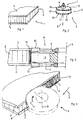
- a composite panel 1 comprises a compressible internal part 2, for example made of cardboard, with a honeycomb structure, enclosed between a first laminar element 3 and a second laminar element 4 that form the visible faces of the panel 1.
- a tool 5 comprises a tool body 6 and a shank 7 that is used for coupling a spindle, or electric spindle, with a machine tool that is not shown that rotates the tool body 6 around an axis 8.
- the tool body 6 comprises a first tool part 9, peripherally provided with a first cutting peripheral crown 10 that has a height, measured along the axis 8, that is at least equal to or hardly greater than the thickness of the first laminar element 3.
- the tool body 6 further comprises a second tool part 11, peripherally provided with a second peripheral cutting crown 12 that has a height, measured along the axis 8, that is the same as or hardly greater than, the thickness of the second laminar element 4.
- the first tool part 9 and the second tool part 11 can be formed of disc-type milling cutters of conventional type, splined on a central hub that is not shown.
- a pressing element 13 having a diameter substantially corresponding to the diameter of the first tool part 9 and of the second tool part 11 and arranged for compressing a more outer peripheral portion 14 of the inner part 2 of the panel 1.
- the pressing element 13 can have a greater diameter than the diameter of the first tool part 9 and of the second tool part 11.
- the pressing element 13 can be symmetrical to the axis 8, for example the pressing element 13 can have a cylindrical shape, with an axis substantially coinciding with the axis 8, or a barrel shape.
- the pressing element 13 can be splined like the first and the second tool part 9, 11 on the same hub.
- the pressing element 13 can be splined on the hub by revolving means, in particular by bearing means.
- the pressing element 13 can be induced to roll around the axis 8 at a speed different from the rotation speed of the first tool part 9 and of the second tool part 11.
- the pressing element 13, by interacting with the peripheral portion 14, can be made to rotate at a speed that is substantially the same as the advancing speed of the tool 5 along the advance direction A.
- the pressing element 13 can be rotated by rotating means that is not shown, at any speed.
- the pressing element 13 might not rotate around the axis 8.
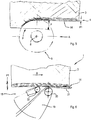
- the peripheral portion 14 is formed by bending the laminae of the honeycomb structure in a direction opposite the advance direction A of the tool 5, which is rotated around the axis 8 in a direction indicated by the arrow F.
- the compressed peripheral portion 14 may be more or less extended: in particular, if the tool 5 is advanced in the direction A at a greater cutting depth P, the peripheral portion 14 occupies a more extended depth PI, whilst if the tool 5 is advanced in the direction A at a lesser cutting depth P, the peripheral portion 14 occupies a less extended depth P1.
- a panel 1 that has a peripheral portion 14 compressed for a certain depth P1 can be directly edge-banded by an edge-banding unit 18 of conventional type, for example comprising a supporting plate 19, an applying roller 20 that presses a finishing strip 21 against the free face of the compressed peripheral portion 14 that provides a sufficiently stable support.
- an applying roller 20 Upstream of the applying roller 20 there is provided a distributing roller 22 that is arranged for distributing a suitable layer of glue on the compressed peripheral portion 14 before the finishing strip 21 is pressed against the peripheral portion 14 whilst the panel 1 is moved along a work direction B.
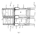
- FIG. 7 there is shown a tool embodiment that is particularly suitable when two panels 1 have to be machined that are superimposed and glued one to the other by a fixing layer 23.
- the first tool part 9 is arranged facing the first laminar element 3 of one of the panels 1 and the second tool part 11 is arranged facing the second laminar element 4 of the other panel 1.
- a further tool part 24 that is peripherally provided with a first cutting part 25 that is arranged at the fixing layer 23 to cut at least the second laminar element 4 of a panel and the first laminar element 3 of the other panel 1.
- a first pressing element 26 Between the first tool part 9 and the further tool part 24 there is interposed a first pressing element 26 and between the further tool part 24 and the second tool part 11 there is interposed a second pressing element 27.
- the first pressing element 26 and the second pressing element 27 are structurally similar to the pressing element 13 and have the same function as the latter.
Landscapes
- Engineering & Computer Science (AREA)
- Life Sciences & Earth Sciences (AREA)
- Manufacturing & Machinery (AREA)
- Mechanical Engineering (AREA)
- Wood Science & Technology (AREA)
- Forests & Forestry (AREA)
- Architecture (AREA)
- Civil Engineering (AREA)
- Structural Engineering (AREA)
- Basic Packing Technique (AREA)
- Auxiliary Devices For And Details Of Packaging Control (AREA)
- Panels For Use In Building Construction (AREA)
Claims (17)
- Outil, comprenant :- un corps d'outil (6) qui est adapté pour être monté sur une machine pour usiner des panneaux en vue d'une rotation autour d'un axe propre (8), dans lequel ledit corps (6) comprend une première partie d'outil (9) et une seconde partie d'outil (11) ;- des éléments de coupe (10, 12 ; 10, 12, 25) agencés sur la périphérie de ladite première partie d'outil (9) et de ladite seconde partie d'outil (11) pour retirer des parties (3, 4 ; 3, 4, 23, 3, 4) d'un panneau (1) à couper, dans lequel lesdits éléments de coupe (10, 12 ; 10, 12, 25) sont agencés dans des couronnes périphérique espacées les unes des autres le long dudit axe (8) pour retirer des parties d'éléments lamellaires (3, 4 ; 3, 4, 23, 3, 4) d'un panneau (1) à usiner ; et- un élément de pression non coupant (13 ; 26, 27) interposé entre au moins deux couronnes consécutives le long dudit axe (8) pour comprimer une partie périphérique (14) d'une structure interne en nid d'abeille (2) dudit panneau (1) ;dans lequel ledit élément de pression non coupant (13 ; 26, 27), ladite première partie d'outil (9) et ladite seconde partie d'outil (11) sont cannelés sur un même moyeu ;
caractérisé en ce que
ledit élément de pression (13 ; 26, 27) a un diamètre correspondant sensiblement au ou supérieur au diamètre de ladite première partie outil (9) et de ladite seconde partie d'outil (11). - Outil selon la revendication 1, dans lequel les éléments de coupe (10, 12 ; 10, 12, 25) font partie de fraises de type disque.
- Outil selon la revendication 1 ou 2, dans lequel lesdits éléments de coupe (10, 12) de chaque couronne appartiennent respectivement à une première portion d'outil axiale (9) et à une seconde portion d'outil axiale (11).
- Outil selon la revendication 3, dans lequel un élément de pression unique (13) est interposé entre ladite première portion d'outil axiale (9) et ladite seconde portion d'outil axiale (11), le long dudit axe (8).
- Outil selon la revendication 4, dans lequel ledit élément de pression unique (13) est sensiblement symétrique audit axe (8).
- Outil selon la revendication 4 ou 5, dans lequel ledit élément de pression unique (13) a une forme sensiblement cylindrique.
- Outil selon l'une quelconque des revendications 4 à 6, et comprenant en outre des moyens de révolution, lesdits moyens de révolution étant interposés entre ledit élément de pression (13) et ledit corps (6).
- Outil selon la revendication 3, dans lequel une portion d'outil axiale supplémentaire (24) est interposée entre ladite première portion d'outil axiale (9) et ladite seconde portion d'outil axiale (11), le long dudit axe (8).
- Outil selon la revendication 8, dans lequel un premier élément de pression (26) est interposé entre ladite première portion d'outil axiale (9) et ladite portion d'outil axiale supplémentaire (24), le long dudit axe (8).
- Outil selon les revendications 8 ou 9, dans lequel un second élément de pression (27) est interposé entre ledit ladite portion d'outil axiale supplémentaire (24) et ladite seconde portion d'outil axiale (11), le long dudit axe (8).
- Outil selon la revendication 9 ou 10, dans lequel ledit premier élément de pression (26) et/ou ledit second élément de pression (27) sont sensiblement symétriques audit axe (8).
- Outil selon l'une quelconque des revendications 9 à 11, dans lequel ledit premier élément de pression (26) et/ou ledit second élément de pression (27) ont une forme sensiblement cylindrique.
- Outil selon l'une quelconque des revendications 9 à 12, dans lequel ledit premier élément de pression (26) et/ou ledit second élément de pression (27) ont sensiblement le même diamètre externe.
- Outil selon l'une quelconque des revendications 9 à 13, et comprenant en outre des moyens de révolution supplémentaires, lesdits moyens de révolution supplémentaires étant interposés entre ledit premier élément de pression (26) et/ou ledit second élément de pression (27) et ledit corps (6).
- Procédé pour plaquer une bande de chant sur un panneau (1) au moyen d'un outil (5) selon l'une quelconque des revendications précédentes, ledit panneau (1) ayant une portion intérieure (2) avec une structure compressible comprise entre deux éléments lamellaires (3, 4) qui définissent les plus larges faces de ceux-ci, comprenant le fait de retirer des portions périphériques de chaque élément lamellaire (3, 4 ; 3, 4, 23) sur une certaine profondeur (P) et comprimer la portion intérieure (2) sensiblement de ladite profondeur, ou plus que ladite profondeur, de manière à définir une partie comprimée (14) qui est adaptée pour agir comme un support pour une bande de finition (21).
- Procédé selon la revendication 15, dans lequel ledit retrait comprend en outre le fait de retirer une zone d'interface (23) le long de laquelle deux panneaux superposés (1) sont réunis ensemble.
- Procédé selon la revendication 16, dans lequel ladite compression comprend le fait de comprimer chaque dite portion intérieure (2) desdits deux panneaux (1) respectifs.
Priority Applications (1)
| Application Number | Priority Date | Filing Date | Title |
|---|---|---|---|
| PL08156526T PL1997597T3 (pl) | 2007-05-21 | 2008-05-20 | Urządzenie i sposób okleinowania brzegów płyt i płyta kompozytowa z oklejonym brzegiem |
Applications Claiming Priority (1)
| Application Number | Priority Date | Filing Date | Title |
|---|---|---|---|
| IT000168A ITMO20070168A1 (it) | 2007-05-21 | 2007-05-21 | Apparato e metodo per bordare pannelli e pannello composito bordato |
Publications (3)
| Publication Number | Publication Date |
|---|---|
| EP1997597A2 EP1997597A2 (fr) | 2008-12-03 |
| EP1997597A3 EP1997597A3 (fr) | 2013-05-08 |
| EP1997597B1 true EP1997597B1 (fr) | 2019-04-03 |
Family
ID=39701102
Family Applications (1)
| Application Number | Title | Priority Date | Filing Date |
|---|---|---|---|
| EP08156526.9A Active EP1997597B1 (fr) | 2007-05-21 | 2008-05-20 | Appareil et procédé pour appliquer un bord de protection et panneau composite avec des bords |
Country Status (3)
| Country | Link |
|---|---|
| EP (1) | EP1997597B1 (fr) |
| IT (1) | ITMO20070168A1 (fr) |
| PL (1) | PL1997597T3 (fr) |
Families Citing this family (6)
| Publication number | Priority date | Publication date | Assignee | Title |
|---|---|---|---|---|
| ITUB20153838A1 (it) * | 2015-09-23 | 2017-03-23 | Samec S P A | Metodo per applicare un elemento di bordatura su un pannello |
| CN108098962A (zh) * | 2017-12-13 | 2018-06-01 | 广州荷力胜蜂窝材料股份有限公司 | 一种蜂窝板镶边机 |
| IT202000004510A1 (it) | 2020-03-04 | 2021-09-04 | Luigino Salvador | Rullo spalmatore per adesivo termofondente |
| AT525069B1 (de) | 2021-08-24 | 2022-12-15 | Brodnik Mag Gerhard | Individualisierung von Selbstbaumöbeln |
| DE102022105259A1 (de) * | 2022-03-07 | 2023-09-07 | Bodo Mündkemüller | Aggregat zur Bearbeitung einer Kantenfläche einer Holzwerkstoffplatte |
| CN115302589B (zh) * | 2022-07-08 | 2023-07-11 | 哈尔滨职业技术学院 | 一种板式家具制造用原材料切割装置及使用方法 |
Citations (5)
| Publication number | Priority date | Publication date | Assignee | Title |
|---|---|---|---|---|
| US2833003A (en) * | 1954-11-22 | 1958-05-06 | Joseph B Bourne | Structural panel |
| DE1033499B (de) * | 1955-10-01 | 1958-07-03 | Hexcel Products Inc | Bahnfoermiges Baumaterial mit wabenfoermigen Zellen und Verfahren zu seiner Herstellung |
| DE1504239A1 (de) * | 1951-01-28 | 1969-11-06 | Furnier Und Sperrholzwerl J We | Verfahren und Pressform zum Beschiehten von Kanten und Profilen |
| US5312504A (en) * | 1992-12-11 | 1994-05-17 | Jorde Edward P | Edge veneering |
| EP1961533A1 (fr) * | 2007-02-26 | 2008-08-27 | Homag Holzbearbeitungssysteme AG | Procédé de collage de matériaux de rebord sur des panneaux de construction légers |
Family Cites Families (2)
| Publication number | Priority date | Publication date | Assignee | Title |
|---|---|---|---|---|
| DE1914403A1 (de) * | 1969-03-21 | 1970-10-08 | Heinrich Brandt Maschb | Fraesvorrichtung zum Beseitigen der ueberstehenden Laengsraender von auf die Stirnflaechen plattenfoermiger Werkstuecke aufgebrachtem Bandmaterial |
| US5433563A (en) * | 1994-08-25 | 1995-07-18 | Fred M. Velepec Co., Inc. | Cutting tool |
-
2007
- 2007-05-21 IT IT000168A patent/ITMO20070168A1/it unknown
-
2008
- 2008-05-20 PL PL08156526T patent/PL1997597T3/pl unknown
- 2008-05-20 EP EP08156526.9A patent/EP1997597B1/fr active Active
Patent Citations (5)
| Publication number | Priority date | Publication date | Assignee | Title |
|---|---|---|---|---|
| DE1504239A1 (de) * | 1951-01-28 | 1969-11-06 | Furnier Und Sperrholzwerl J We | Verfahren und Pressform zum Beschiehten von Kanten und Profilen |
| US2833003A (en) * | 1954-11-22 | 1958-05-06 | Joseph B Bourne | Structural panel |
| DE1033499B (de) * | 1955-10-01 | 1958-07-03 | Hexcel Products Inc | Bahnfoermiges Baumaterial mit wabenfoermigen Zellen und Verfahren zu seiner Herstellung |
| US5312504A (en) * | 1992-12-11 | 1994-05-17 | Jorde Edward P | Edge veneering |
| EP1961533A1 (fr) * | 2007-02-26 | 2008-08-27 | Homag Holzbearbeitungssysteme AG | Procédé de collage de matériaux de rebord sur des panneaux de construction légers |
Also Published As
| Publication number | Publication date |
|---|---|
| EP1997597A2 (fr) | 2008-12-03 |
| EP1997597A3 (fr) | 2013-05-08 |
| ITMO20070168A1 (it) | 2008-11-22 |
| PL1997597T3 (pl) | 2019-09-30 |
Similar Documents
| Publication | Publication Date | Title |
|---|---|---|
| EP1997597A2 (fr) | Appareil et procédé pour appliquer un bord de protection et panneau composite avec des bords | |
| EP3105009B1 (fr) | Machine mobile pour l'usinage des bords d'une planche d'un meuble en bois | |
| CA2455195A1 (fr) | Coupeuse rotative et methode de fabrication de produits fibreux a l'aide de cette machine | |
| US5529100A (en) | Apparatus for dehydrating softwood veneer | |
| JP3597441B2 (ja) | 積層材の曲げ加工方法 | |
| CN111283816B (zh) | 一种卫星式圆刀模切机 | |
| KR101419493B1 (ko) | 회전형 화장지 커팅장치 | |
| KR20220109924A (ko) | 골판지를 이용한 다용도 판지 제조방법 및 그 제조방법에 의해 제조된 다용도 판지 | |
| US10493652B2 (en) | Veneer peeling apparatus | |
| US5411066A (en) | Method of producing veneer | |
| EP2993004B1 (fr) | Dispositif d'ébavurage pour bois raboté, et dispositif de fabrication ainsi que de fabrication d'article revêtu | |
| EP4260955B1 (fr) | Dispositif de post-traitement d'au moins une pièce en forme de plaque | |
| JP4712260B2 (ja) | ウェブを加工するための力調節可能な回転装置 | |
| KR20160003094A (ko) | 화장재의 접착 장치 및 피복 제품의 제조 장치, 및 화장재의 접착 방법 및 피복 제품의 제조 방법 | |
| CN102066092A (zh) | 条带切割系统 | |
| FI121808B (fi) | Viistejyrsin | |
| EP1488128B1 (fr) | Support de garniture de friction, en particulier sabot de frein, pour frein de stationnement ou frein a tambour, procede de production correspondant et dispositif pour mettre en oeuvre ce procede | |
| US20060185414A1 (en) | Method and apparatus for producing cylindrical components having bent portions | |
| JP2012111065A (ja) | 製本用無線綴じ方法と同方法の実施に使用する中本処理装置 | |
| KR100350106B1 (ko) | 천연목재를 이용한 래핑시트 및 우드롤 | |
| KR102109766B1 (ko) | 패널의 엣지 접착 장치 | |
| JPH047885B2 (fr) | ||
| WO1999061204A1 (fr) | Feuille d'amortissement de vibrations destinee a des disques de coupe | |
| JPH02220805A (ja) | ベニヤレース | |
| CN112606139A (zh) | 一种用于防止板材封边时产生溢胶的盘式铣刀和方法 |
Legal Events
| Date | Code | Title | Description |
|---|---|---|---|
| PUAI | Public reference made under article 153(3) epc to a published international application that has entered the european phase |
Free format text: ORIGINAL CODE: 0009012 |
|
| AK | Designated contracting states |
Kind code of ref document: A2 Designated state(s): AT BE BG CH CY CZ DE DK EE ES FI FR GB GR HR HU IE IS IT LI LT LU LV MC MT NL NO PL PT RO SE SI SK TR |
|
| AX | Request for extension of the european patent |
Extension state: AL BA MK RS |
|
| PUAL | Search report despatched |
Free format text: ORIGINAL CODE: 0009013 |
|
| AK | Designated contracting states |
Kind code of ref document: A3 Designated state(s): AT BE BG CH CY CZ DE DK EE ES FI FR GB GR HR HU IE IS IT LI LT LU LV MC MT NL NO PL PT RO SE SI SK TR |
|
| AX | Request for extension of the european patent |
Extension state: AL BA MK RS |
|
| RIC1 | Information provided on ipc code assigned before grant |
Ipc: B29C 63/00 20060101ALI20130404BHEP Ipc: B27D 5/00 20060101AFI20130404BHEP Ipc: E04C 2/36 20060101ALI20130404BHEP Ipc: B32B 3/02 20060101ALI20130404BHEP |
|
| 17P | Request for examination filed |
Effective date: 20131108 |
|
| RBV | Designated contracting states (corrected) |
Designated state(s): AT BE BG CH CY CZ DE DK EE ES FI FR GB GR HR HU IE IS IT LI LT LU LV MC MT NL NO PL PT RO SE SI SK TR |
|
| AKX | Designation fees paid |
Designated state(s): AT BE BG CH CY CZ DE DK EE ES FI FR GB GR HR HU IE IS IT LI LT LU LV MC MT NL NO PL PT RO SE SI SK TR |
|
| 17Q | First examination report despatched |
Effective date: 20150106 |
|
| STAA | Information on the status of an ep patent application or granted ep patent |
Free format text: STATUS: EXAMINATION IS IN PROGRESS |
|
| REG | Reference to a national code |
Ref country code: DE Ref legal event code: R079 Ref document number: 602008059572 Country of ref document: DE Free format text: PREVIOUS MAIN CLASS: B27D0005000000 Ipc: B27D0001060000 |
|
| GRAP | Despatch of communication of intention to grant a patent |
Free format text: ORIGINAL CODE: EPIDOSNIGR1 |
|
| STAA | Information on the status of an ep patent application or granted ep patent |
Free format text: STATUS: GRANT OF PATENT IS INTENDED |
|
| RIC1 | Information provided on ipc code assigned before grant |
Ipc: A47B 96/20 20060101ALI20180928BHEP Ipc: B27D 1/06 20060101AFI20180928BHEP |
|
| INTG | Intention to grant announced |
Effective date: 20181019 |
|
| GRAS | Grant fee paid |
Free format text: ORIGINAL CODE: EPIDOSNIGR3 |
|
| GRAA | (expected) grant |
Free format text: ORIGINAL CODE: 0009210 |
|
| STAA | Information on the status of an ep patent application or granted ep patent |
Free format text: STATUS: THE PATENT HAS BEEN GRANTED |
|
| AK | Designated contracting states |
Kind code of ref document: B1 Designated state(s): AT BE BG CH CY CZ DE DK EE ES FI FR GB GR HR HU IE IS IT LI LT LU LV MC MT NL NO PL PT RO SE SI SK TR |
|
| REG | Reference to a national code |
Ref country code: GB Ref legal event code: FG4D |
|
| REG | Reference to a national code |
Ref country code: CH Ref legal event code: EP Ref country code: AT Ref legal event code: REF Ref document number: 1115156 Country of ref document: AT Kind code of ref document: T Effective date: 20190415 |
|
| REG | Reference to a national code |
Ref country code: DE Ref legal event code: R096 Ref document number: 602008059572 Country of ref document: DE |
|
| REG | Reference to a national code |
Ref country code: IE Ref legal event code: FG4D |
|
| REG | Reference to a national code |
Ref country code: NL Ref legal event code: MP Effective date: 20190403 |
|
| REG | Reference to a national code |
Ref country code: LT Ref legal event code: MG4D |
|
| PG25 | Lapsed in a contracting state [announced via postgrant information from national office to epo] |
Ref country code: NL Free format text: LAPSE BECAUSE OF FAILURE TO SUBMIT A TRANSLATION OF THE DESCRIPTION OR TO PAY THE FEE WITHIN THE PRESCRIBED TIME-LIMIT Effective date: 20190403 |
|
| PG25 | Lapsed in a contracting state [announced via postgrant information from national office to epo] |
Ref country code: ES Free format text: LAPSE BECAUSE OF FAILURE TO SUBMIT A TRANSLATION OF THE DESCRIPTION OR TO PAY THE FEE WITHIN THE PRESCRIBED TIME-LIMIT Effective date: 20190403 Ref country code: CZ Free format text: LAPSE BECAUSE OF FAILURE TO SUBMIT A TRANSLATION OF THE DESCRIPTION OR TO PAY THE FEE WITHIN THE PRESCRIBED TIME-LIMIT Effective date: 20190403 Ref country code: LT Free format text: LAPSE BECAUSE OF FAILURE TO SUBMIT A TRANSLATION OF THE DESCRIPTION OR TO PAY THE FEE WITHIN THE PRESCRIBED TIME-LIMIT Effective date: 20190403 Ref country code: HR Free format text: LAPSE BECAUSE OF FAILURE TO SUBMIT A TRANSLATION OF THE DESCRIPTION OR TO PAY THE FEE WITHIN THE PRESCRIBED TIME-LIMIT Effective date: 20190403 Ref country code: FI Free format text: LAPSE BECAUSE OF FAILURE TO SUBMIT A TRANSLATION OF THE DESCRIPTION OR TO PAY THE FEE WITHIN THE PRESCRIBED TIME-LIMIT Effective date: 20190403 Ref country code: PT Free format text: LAPSE BECAUSE OF FAILURE TO SUBMIT A TRANSLATION OF THE DESCRIPTION OR TO PAY THE FEE WITHIN THE PRESCRIBED TIME-LIMIT Effective date: 20190803 Ref country code: NO Free format text: LAPSE BECAUSE OF FAILURE TO SUBMIT A TRANSLATION OF THE DESCRIPTION OR TO PAY THE FEE WITHIN THE PRESCRIBED TIME-LIMIT Effective date: 20190703 Ref country code: SE Free format text: LAPSE BECAUSE OF FAILURE TO SUBMIT A TRANSLATION OF THE DESCRIPTION OR TO PAY THE FEE WITHIN THE PRESCRIBED TIME-LIMIT Effective date: 20190403 |
|
| PG25 | Lapsed in a contracting state [announced via postgrant information from national office to epo] |
Ref country code: LV Free format text: LAPSE BECAUSE OF FAILURE TO SUBMIT A TRANSLATION OF THE DESCRIPTION OR TO PAY THE FEE WITHIN THE PRESCRIBED TIME-LIMIT Effective date: 20190403 Ref country code: GR Free format text: LAPSE BECAUSE OF FAILURE TO SUBMIT A TRANSLATION OF THE DESCRIPTION OR TO PAY THE FEE WITHIN THE PRESCRIBED TIME-LIMIT Effective date: 20190704 Ref country code: BG Free format text: LAPSE BECAUSE OF FAILURE TO SUBMIT A TRANSLATION OF THE DESCRIPTION OR TO PAY THE FEE WITHIN THE PRESCRIBED TIME-LIMIT Effective date: 20190703 |
|
| REG | Reference to a national code |
Ref country code: CH Ref legal event code: PL |
|
| PG25 | Lapsed in a contracting state [announced via postgrant information from national office to epo] |
Ref country code: IS Free format text: LAPSE BECAUSE OF FAILURE TO SUBMIT A TRANSLATION OF THE DESCRIPTION OR TO PAY THE FEE WITHIN THE PRESCRIBED TIME-LIMIT Effective date: 20190803 |
|
| REG | Reference to a national code |
Ref country code: DE Ref legal event code: R097 Ref document number: 602008059572 Country of ref document: DE |
|
| PG25 | Lapsed in a contracting state [announced via postgrant information from national office to epo] |
Ref country code: MC Free format text: LAPSE BECAUSE OF FAILURE TO SUBMIT A TRANSLATION OF THE DESCRIPTION OR TO PAY THE FEE WITHIN THE PRESCRIBED TIME-LIMIT Effective date: 20190403 Ref country code: RO Free format text: LAPSE BECAUSE OF FAILURE TO SUBMIT A TRANSLATION OF THE DESCRIPTION OR TO PAY THE FEE WITHIN THE PRESCRIBED TIME-LIMIT Effective date: 20190403 Ref country code: LI Free format text: LAPSE BECAUSE OF NON-PAYMENT OF DUE FEES Effective date: 20190531 Ref country code: CH Free format text: LAPSE BECAUSE OF NON-PAYMENT OF DUE FEES Effective date: 20190531 Ref country code: EE Free format text: LAPSE BECAUSE OF FAILURE TO SUBMIT A TRANSLATION OF THE DESCRIPTION OR TO PAY THE FEE WITHIN THE PRESCRIBED TIME-LIMIT Effective date: 20190403 Ref country code: SK Free format text: LAPSE BECAUSE OF FAILURE TO SUBMIT A TRANSLATION OF THE DESCRIPTION OR TO PAY THE FEE WITHIN THE PRESCRIBED TIME-LIMIT Effective date: 20190403 Ref country code: DK Free format text: LAPSE BECAUSE OF FAILURE TO SUBMIT A TRANSLATION OF THE DESCRIPTION OR TO PAY THE FEE WITHIN THE PRESCRIBED TIME-LIMIT Effective date: 20190403 |
|
| REG | Reference to a national code |
Ref country code: BE Ref legal event code: MM Effective date: 20190531 |
|
| PLBE | No opposition filed within time limit |
Free format text: ORIGINAL CODE: 0009261 |
|
| STAA | Information on the status of an ep patent application or granted ep patent |
Free format text: STATUS: NO OPPOSITION FILED WITHIN TIME LIMIT |
|
| PG25 | Lapsed in a contracting state [announced via postgrant information from national office to epo] |
Ref country code: LU Free format text: LAPSE BECAUSE OF NON-PAYMENT OF DUE FEES Effective date: 20190520 |
|
| 26N | No opposition filed |
Effective date: 20200106 |
|
| GBPC | Gb: european patent ceased through non-payment of renewal fee |
Effective date: 20190703 |
|
| PG25 | Lapsed in a contracting state [announced via postgrant information from national office to epo] |
Ref country code: TR Free format text: LAPSE BECAUSE OF FAILURE TO SUBMIT A TRANSLATION OF THE DESCRIPTION OR TO PAY THE FEE WITHIN THE PRESCRIBED TIME-LIMIT Effective date: 20190403 |
|
| PG25 | Lapsed in a contracting state [announced via postgrant information from national office to epo] |
Ref country code: GB Free format text: LAPSE BECAUSE OF NON-PAYMENT OF DUE FEES Effective date: 20190703 Ref country code: IE Free format text: LAPSE BECAUSE OF NON-PAYMENT OF DUE FEES Effective date: 20190520 |
|
| REG | Reference to a national code |
Ref country code: AT Ref legal event code: UEP Ref document number: 1115156 Country of ref document: AT Kind code of ref document: T Effective date: 20190403 |
|
| PG25 | Lapsed in a contracting state [announced via postgrant information from national office to epo] |
Ref country code: BE Free format text: LAPSE BECAUSE OF NON-PAYMENT OF DUE FEES Effective date: 20190531 Ref country code: SI Free format text: LAPSE BECAUSE OF FAILURE TO SUBMIT A TRANSLATION OF THE DESCRIPTION OR TO PAY THE FEE WITHIN THE PRESCRIBED TIME-LIMIT Effective date: 20190403 |
|
| PG25 | Lapsed in a contracting state [announced via postgrant information from national office to epo] |
Ref country code: FR Free format text: LAPSE BECAUSE OF NON-PAYMENT OF DUE FEES Effective date: 20190603 |
|
| PG25 | Lapsed in a contracting state [announced via postgrant information from national office to epo] |
Ref country code: CY Free format text: LAPSE BECAUSE OF FAILURE TO SUBMIT A TRANSLATION OF THE DESCRIPTION OR TO PAY THE FEE WITHIN THE PRESCRIBED TIME-LIMIT Effective date: 20190403 |
|
| PG25 | Lapsed in a contracting state [announced via postgrant information from national office to epo] |
Ref country code: HU Free format text: LAPSE BECAUSE OF FAILURE TO SUBMIT A TRANSLATION OF THE DESCRIPTION OR TO PAY THE FEE WITHIN THE PRESCRIBED TIME-LIMIT; INVALID AB INITIO Effective date: 20080520 Ref country code: MT Free format text: LAPSE BECAUSE OF FAILURE TO SUBMIT A TRANSLATION OF THE DESCRIPTION OR TO PAY THE FEE WITHIN THE PRESCRIBED TIME-LIMIT Effective date: 20190403 |
|
| PGFP | Annual fee paid to national office [announced via postgrant information from national office to epo] |
Ref country code: PL Payment date: 20210507 Year of fee payment: 14 Ref country code: AT Payment date: 20210518 Year of fee payment: 14 |
|
| REG | Reference to a national code |
Ref country code: AT Ref legal event code: MM01 Ref document number: 1115156 Country of ref document: AT Kind code of ref document: T Effective date: 20220520 |
|
| PG25 | Lapsed in a contracting state [announced via postgrant information from national office to epo] |
Ref country code: AT Free format text: LAPSE BECAUSE OF NON-PAYMENT OF DUE FEES Effective date: 20220520 |
|
| P01 | Opt-out of the competence of the unified patent court (upc) registered |
Effective date: 20230518 |
|
| PG25 | Lapsed in a contracting state [announced via postgrant information from national office to epo] |
Ref country code: PL Free format text: LAPSE BECAUSE OF NON-PAYMENT OF DUE FEES Effective date: 20220520 |
|
| PGFP | Annual fee paid to national office [announced via postgrant information from national office to epo] |
Ref country code: DE Payment date: 20250519 Year of fee payment: 18 |
|
| PGFP | Annual fee paid to national office [announced via postgrant information from national office to epo] |
Ref country code: IT Payment date: 20260206 Year of fee payment: 19 |